Table of Contents
Advertisement
Quick Links
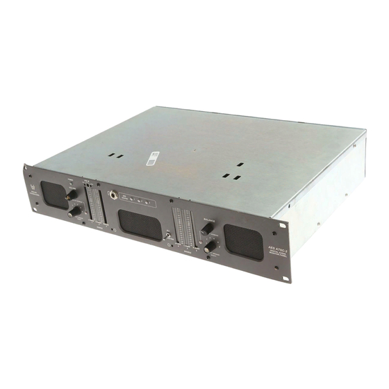
2U Monitor Speaker Unit with
6 Analog Inputs, Selected Analog Outputs,
Headphone Output, 6 Channel Monitoring,
6 Level Meters, and Phase Indication
Document P/N 821509 Rev-C
Title and Contents ...............................................................
Important Safety Instructions and Introduction ..............................
Description and Features ..............................................................
General Specifications ..................................................................
Section 1: Operation ..........................................................
Front Panel Controls and Indicators .............................................
Rear Panel Connectors ................................................................
Section 2: Tech Support .................................................
Service and Troubleshooting Guide ..............................................
Audio Circuit Description .............................................................
Phase Indication and Level Metering Description ...........................
Analog Input Block Diagram .........................................................
Interconnect Block Diagram .........................................................
Note: This manual is specifically applicable to the standard version of the ATSC-1. For
information about any custom options, which are installed in the unit, please refer to the
relevant separate addendum, which should be furnished with this manual.
© 2006 Wohler Technologies Inc. ALL rights reserved
ATSC-1
CONTENTS
1
3
4
5
7
8
12
15
16
17
18
20
21
1
Advertisement
Table of Contents

Related Manuals for Wohler ATSC-1


Summary of Contents for Wohler ATSC-1
-
Page 1: Table Of Contents
Analog Input Block Diagram ............Interconnect Block Diagram ............Note: This manual is specifically applicable to the standard version of the ATSC-1. For information about any custom options, which are installed in the unit, please refer to the relevant separate addendum, which should be furnished with this manual. - Page 2 Introduction Congratulations on your selection of a Wohler Technologies ATSC-1 audio monitor unit. We are confident it represents the best performance and value available, and we guarantee your satisfaction with it. If you have questions or comments you may contact us at: Wohler Technologies, Inc.
-
Page 3: Heat Dissipation
Audio Connections Connection of the audio feeds is straightforward. The system block diagram located on page 24 may be referred to for clarification of the general signal paths into and out of the ATSC-1 unit. Electrical Interference As with any audio equipment, maximum immunity from electrical interference requires the use of shielded cable;... - Page 4 "Surround Sound" programming. The unit is 2RU in size, for excellent fidelity without using excessive rackspace in the critical ‘operating zone’ of rack bays and consoles. The ATSC-1 input accepts six separate analog signals. These audio inputs can handles monitoring requirements throughout the facility.
-
Page 5: General Specifications
Designed for optimum reproduction in relatively close-up use, the ATSC-1 unit has more than enough acoustic output, even for noisy transmitter sites (104 dB SPL at two feet), and a surprisingly broad and smooth useable frequency response of 40 Hz to 18 kHz. - Page 6 (This page left intentionally blank) © 2006 Wohler Technologies Inc. ALL rights reserved...
-
Page 7: Section 1: Operation
Section 1: Operation Front Panel Controls and Indicators Rear Panel Connectors and Settings © 2006 Wohler Technologies Inc. ALL rights reserved... - Page 8 Please refer to Figure 1a on the following page to familiarize yourself with the front panel controls and indicators of the ATSC-1 unit. The following sections describe the functions of each of the various controls and indicators found on the front panel. The numbers associated with each heading of the following sections refer to the item reference “balloon”...
- Page 9 Figure 1a.- ATSC-1 Front Panel Controls and Indicators © 2006 Wohler Technologies Inc. ALL rights reserved...
-
Page 10: Volume Control
Power Indicator LED The Power Indication LED signals the operating condition of the power supply. The LED glows green to indicate the ATSC-1 is connected to mains power and an operation voltage is present. Left Speaker Select Rotary Switch This six position rotary switch allows you to isolate and monitor any one of the six possible channels through the left speaker. - Page 11 Figure 1a.- ATSC-1 Front Panel Controls and Indicators © 2006 Wohler Technologies Inc. ALL rights reserved...
- Page 12 REAR PANEL CONNECTORS AND SETTINGS Please refer to Figure 1b on the following page to familiarize yourself with the rear panel features of the ATSC-1 unit. The following sections describe, in some detail, the functions of each of the various features found on the rear panel.
- Page 13 Figure 1b.- ATSC-2 Rear Panel Connectors and Settings © 2006 Wohler Technologies Inc. ALL rights reserved...
- Page 14 (This page left intentionally blank) © 2006 Wohler Technologies Inc. ALL rights reserved...
- Page 15 Section 2: Technical Support Service and Toubleshooting Guide Audio Circuit Description Phase Indication Interconnect Block Diagram © 2006 Wohler Technologies Inc. ALL rights reserved...
-
Page 16: Service And Troubleshooting Guide
(common) OR THE GROUNDED LEAD OF ANY TEST EQUIPMENT so as not to short out the power amps. The side speaker outputs are single-ended, so these precautions are not necessary for them. © 2006 Wohler Technologies Inc. ALL rights reserved... -
Page 17: Audio Circuit Description
Power amps IC19 and IC21 are arranged in a differential input push-pull output. NOTE: There are NO coupling capacitors on the power amp outputs; care must be used to avoid shorting EITHER speaker terminal to chassis, so that destructive DC currents are not accidentally passed through the woofer! © 2006 Wohler Technologies Inc. ALL rights reserved... - Page 18 Due to the highly proprietary nature of this circuit, detailed information is not available. This circuit is, however, very reliable, and is warranted against defects for an additional year (three years compared to the usual two years for standard Wohler products.)
- Page 19 IC5A is configured as a comparator, nominally set at 6dB above “0” to drive the topmost segment of the upper bargraph display as a peak indicator. The peak segment's threshold is set by P2. © 2006 Wohler Technologies Inc. ALL rights reserved...
-
Page 20: Analog Input Block Diagram
ATSC-1 Analog Input Block Diagram © 2006 Wohler Technologies Inc. ALL rights reserved... -
Page 21: Interconnect Block Diagram
ATSC-1 System Interconnect Block Diagram © 2006 Wohler Technologies Inc. ALL rights reserved... - Page 22 Technologies, Inc. Phone: (510) 589-5676 31055 Huntwood Avenue Fax: (510) 870-0811 Hayward, CA 94544 US Toll-Free: 1-888-596-4537 Phone: (510) 870-0810 web: www.wohler.com Fax: (510) 870-0811 e-mail: support@wohler.com US Toll-Free: 1-888-596-4537 www.wohler.com support@wohler.com © 2006 Wohler Technologies Inc. ALL rights reserved...
Need help?
Do you have a question about the ATSC-1 and is the answer not in the manual?
Questions and answers