Table of Contents
Advertisement
AMP2A and AMP2A-2S
with Two Analog Inputs and Loop-through
Outputs on XLR (AMP2A) or Two Pair
(Selectable) Analog Inputs and Selected Stereo
Outputs on XLR (AMP2A-2S), Dual 20-Segment
LED Level Meters and Phase Indication
Title and Contents ......................................................
Important Safety Instructions and Introduction ....................................
Section 1: General Features and Specs ..................
Description and Features ..................................................................
Applications, Specifications, and Other Options ..............................
Section 2: Operation ..................................................
Installation .......................................................................................
Front Panel Features ........................................................................
Rear Panel Features .........................................................................
Section 3: Technical Information ............................
General Technical Observations ......................................................
Level Meter Settings and Specifications ...........................................
LED Bargraph Driver PCB (919030) Description ...........................
Level Meter Bargraph "0" (Zero) Fine Adjustment ..........................
Level Meter Bargraph Peak LED Segment Adjustment ....................
AMP2A Interconnect Block Diagram ...............................................
AMP2A-2S Interconnect Block Diagram ...........................................
Document P/N 821553 Rev-B
User Manual
CONTENTS
1
2
3
4
5
7
9
10
12
15
16
17
18
19
19
20
21
1
Advertisement
Table of Contents

Related Manuals for Wohler AMP2A


Summary of Contents for Wohler AMP2A
-
Page 1: Table Of Contents
AMP2A and AMP2A-2S 2U Stereo Audio Speaker Monitors with Two Analog Inputs and Loop-through Outputs on XLR (AMP2A) or Two Pair (Selectable) Analog Inputs and Selected Stereo Outputs on XLR (AMP2A-2S), Dual 20-Segment LED Level Meters and Phase Indication Document P/N 821553 Rev-B... - Page 2 Introduction Congratulations on your selection of a Wohler Technologies product. We are confident it represents the best performance and value available, and we guarantee your satisfaction with it. If you have questions or comments you may contact us at: Wohler Technologies, Inc.
- Page 3 AMP2A and AMP2A-2S User Manual P/N 821553 Rev-B Section 1 General Features and Specifications Description Features Applications Specifications Other Options © 2006 Wohler Technologies Inc. ALL rights reserved...
-
Page 4: Stereo Audio Speaker Monitors
The AMP2-2S model features a toggle switch on the front panel to allow selection of an additional pair of analog input sources. The rear panel for the AMP2A model features two analog inputs on balanced XLR and unbalanced RCA connectors and two loop- through outputs on XLR connectors. - Page 5 The AMP2A Series units are ideally suited for use in VTR bays, mobile production vehicles, teleconferencing installations, multimedia systems, satellite links and cable TV facilities, and on-air radio studios. Designed and manufactured in the U.S., AMP2A Series units are backed by a strong warranty and a satisfaction guaranteed return policy.
- Page 6 AMP2A and AMP2A-2S User Manual P/N 821553 Rev-B (This page left intentionally blank) © 2006 Wohler Technologies Inc. ALL rights reserved...
-
Page 7: Section 2: Operation
AMP2A and AMP2A-2S User Manual P/N 821553 Rev-B Section 2 Operation Installation Front Panel Features Rear Panel Features © 2006 Wohler Technologies Inc. ALL rights reserved... - Page 8 AMP2A and AMP2A-2S User Manual P/N 821553 Rev-B Section 2: Operation (This page left intentionally blank) © 2006 Wohler Technologies Inc. ALL rights reserved...
- Page 9 Connection of the audio feeds is straightforward. Please refer to the system interconnect block diagrams on pages 20 and 21 for clarification of the general signal paths into and out of the AMP2A and AMP2A-2S units. Analog inputs via the 3-pin female XLR connectors are configured for 200K Ω balanced connections. RCA connector inputs (AMP2A only) are configured for 47K Ω...
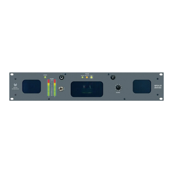
- Page 10 Section 2: Operation Front Panel Features Please refer to Figure-2a on the following page to familiarize yourself with the front panel features of the AMP2A and AMP2A-2S units. The following sections describe these features and are referenced, by number, to Figure-2a.
- Page 11 AMP2A and AMP2A-2S User Manual P/N 821553 Rev-B Section 2: Operation AMP2A-2S AMP2A Front Panel Front Panel Figure-2a: Front Panel Features © 2006 Wohler Technologies Inc. ALL rights reserved...
- Page 12 Section 2: Operation Rear Panel Features Please refer to Figure-2b on the following page to familiarize yourself with the rear panel features of the AMP2A and AMP2A-2S units. The following sections describe these features and are referenced, by letter, to Figure-2b.
- Page 13 AMP2A and AMP2A-2S User Manual P/N 821553 Rev-B Section 2: Operation AMP2A-2S AMP2A Rear Panel Rear Panel Figure-2b: Rear Panel Features © 2006 Wohler Technologies Inc. ALL rights reserved...
- Page 14 AMP2A and AMP2A-2S User Manual P/N 821553 Rev-B Section 2: Operation (This page left intentionally blank) © 2006 Wohler Technologies Inc. ALL rights reserved...
-
Page 15: Section 3: Technical Information
AMP2A and AMP2A-2S User Manual P/N 821553 Rev-B Section 3 Technical Information • General Technical Observations • Level Meter Settings and Specifications • LED Bargraph Driver PCB (919030) Description • Level Meter Bargraph "0" (Zero) Level Fine Adjustment • Level Meter Bargraph Peak LED Segment Adjustment •... - Page 16 General Audio Circuitry Observations The AMP2A series units may use one of two possible Audio Amplifier PC boards; the 919100-2 or the 919164. Both amplifier circuits offer the same specifications and performance. Improvements of the 919164 over the older 919100-2 have to do prmarily with manufacturability.
- Page 17 AMP2A and AMP2A-2S User Manual P/N 821553 Rev-B Section 3: Technical Information Level Meter Settings and Specifications Level Meter DIP Switch Settings Two DIP switch modules, accessed through holes in the top cover, allow the user to set the VU/PPM Display Mode and Input Level Gain Calibration.
- Page 18 PCB. A choice of four different reference levels, -6, 0, +4, and +8 dB for the 0 dB indication are available for selection by the user. A chart showing these input gain calibration settings can be found on page 17 and on a label on the top cover of the AMP2A unit.
-
Page 19: Level Meter Bargraph "0" (Zero) Fine Adjustment
AMP2A and AMP2A-2S User Manual P/N 821553 Rev-B Level Meter Bargraph "0" (Zero) Fine Adjustment 1) Removal of the Top Cover Remove the top cover screws (2 along upper front panel, 2 per each side, 3 along upper rear panel, 1 center top). The 919030 PCBs (2 each) are vertically mounted to chassis bottom just behind the front panel mounted LED bargraph displays;... - Page 20 AMP2A and AMP2A-2S User Manual P/N 821553 Rev-B Section 3: Technical Information © 2006 Wohler Technologies Inc. ALL rights reserved...
- Page 21 AMP2A and AMP2A-2S User Manual P/N 821553 Rev-B Section 3: Technical Information © 2006 Wohler Technologies Inc. ALL rights reserved...
- Page 22 AMP2A and AMP2A-2S User Manual P/N 821553 Rev-B Wohler Technologies, Inc. You can now contact us at: 31055 Huntwood Avenue Wohler Hayward, CA 94544 Technologies, Inc. Phone: (510) 589-5676 31055 Huntwood Avenue Fax: (510) 870-0811 Hayward, CA 94544 US Toll-Free: 1-888-596-4537 Phone: (510) 870-0810 web: www.wohler.com...
Need help?
Do you have a question about the AMP2A and is the answer not in the manual?
Questions and answers