
Related Manuals for PB Heat TC Series


Summary of Contents for PB Heat TC Series
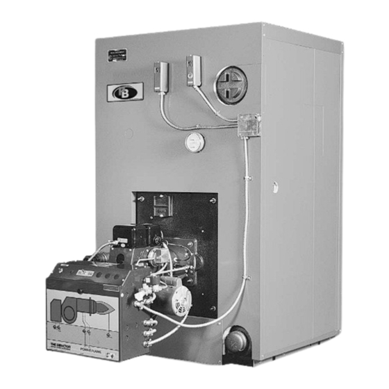
- Page 1 Series ™ Oil, Gas & Gas/Oil Boilers I n s t a l l a t i o n , O p e r a t i o n & M a i n t e n a n c e M a n u a l...
-
Page 2: Table Of Contents
TABLE OF CONTENTS TABLE OF CONTENTS USING THIS MANUAL 3. INSTALLATION A. MANUAL ORGANIZATION ....1 A. PREPARATION ..... . .16 B. -
Page 3: Using This Manual
CAUTION special notice of potential hazards. These categories mean, in the judgment of the PB Heat, LLC: Indicates a condition or hazard which will or can cause moderate personal injury or property damage. -
Page 4: Preinstallation
PREINSTALLATION 1. PREINSTALLATION ANSI/NFPA 211 – "Chimneys, Fireplaces, Vents and A. GENERAL Solid Fuel Burning Appliances" Series TC™ boilers are supplied completely knocked 3. In Canada, the following codes should be used in down for field assembly, completely assembled as addition to those in Section 1.B.2. -
Page 5: Combustion & Ventilation Air
If extreme length, excessive elbows, or a isolated from these appliances. reduction in diameter is necessary, consult your PB Heat representative for recommendations. b) If the vent system terminates in any area where wind-generated down drafts are likely, install a... -
Page 6: Boiler Foundation
PREINSTALLATION 3. Vent System Installation: g) Multiple Appliances: Do not vent multiple appliances with venting that operates under a) The vent system and installation must be in positive pressure into a common chimney or vent accordance with the current edition of the connector. -
Page 7: Installation Survey
For new and existing installations, a Steam or Water between the main floor and the top of the boiler Installation Survey is available from PB Heat, LLC. The foundation. survey will provide information on how a steam or water... -
Page 8: Planning The Layout
PREINSTALLATION c) In some cases, the Burner and/or Gas Train may H. PLANNING THE LAYOUT be shipped separately. Prepare sketches and notes of the layout to minimize the d) The Optional Barometric Draft Damper is possibility of interference with new or existing shipped in a separate carton. - Page 9 PREINSTALLATION Table 1.2b: Series TC™ Shipping List (Water Boilers) Standard Sections Flue Outlet Jacket Panels Qty. TC-04 SCN 74004 76000 76001 76002 76060 78510 77030 76072 76050 76053 76070 75004 76030 76031 Qty. TC-05 SCN 74005 76000 76001 76002 76060 78510 77031 76072 76051 76054 76070 75005 76030 76032...
- Page 10 PREINSTALLATION Table 1.3: Burner Mounting Plates Power Flame Power Flame Beckett Carlin Gordon-Piatt (Gas) Power Flame (Oil) (Gas/Oil) Webster Boiler Burner Burner Burner Burner Burner Burner Burner Model Model Model Model Model Model Model Model TC-04 76028 J30A CF1400 702CRD 76028 76028 TC-05...
-
Page 11: Boiler Assembly
2. Report any damage to the shipping company and 6. Inspect the port connector recesses and rope groove PB Heat immediately. on the cast iron rear section for dirt and obstructions. 3. Lay the angle rails provided at the point of final 7. - Page 12 ASSEMBLY 10. Install the large graphite port connector with steel inner ring into the upper port making sure that the inner ring stays inside the port connector. NOTICE Handle the graphite port connectors with care. Do not bend, twist, stretch or drop the port connectors. If the graphite port conector is damaged it must be replaced.
- Page 13 ASSEMBLY 17. Gently tighten the draw rods to the torque 18. If any ports develop leaks during the hydrostatic test, specification and sequence as described in Table 2.1. the torque may be increased up to 200 ft. lbs. [270 Make sure the port connectors stay inside the boiler Nm] on the upper right and 150 ft.
- Page 14 ASSEMBLY Table 2.2b: Water Section Arrangement TC-04 TC-05 TC-06 P H B TC-07 P H B TC-08 P H P H B TC-09 P H P P H B TC-10 H P H P P H B TC-11 P H P P H B TC-12 P H P H P H B...
-
Page 15: Hydrostatic Testing
ASSEMBLY Table 2.3: Splice Piece Nut & Washer Locations Boiler Model Splice Piece & Washer Locations TC-04 TC-05 TC-06 TC-07 TC-08 Between Sections 3-4 & Sections 5-6 TC-09 3-4 & 5-6 TC-10 5-6 & 7-8 TC-11 5-6 & 7-8 TC-12 5-6 &... -
Page 16: Burner Mounting Plate
ASSEMBLY 4. Insert the Burner Insulation Block into the burner opening with the notch for the Observation Port on the top left side. 5. Place the Burner Mounting Plate over the block and force the block inward until the Studs extend far enough through the holes to accept 7/16"... -
Page 17: Flue Collector Installation
ASSEMBLY 2. Thread the 5/16" x 1-1/2" studs into the screw seats BURNER MOUNTING around the rear observation port opening in the Boiler Back Section. 1. Read the Burner Instruction Manual before starting. 3. Apply a thin layer of furnace cement over the 2. -
Page 18: Installation
Use nipples long enough to extend through the jacket. B. STEAM BOILER PIPING 1. Refer to the PB Heat Steam Installation Survey for guidance with steam boiler piping and components. 2. Piping for steam boilers is shown in Figure 3.1, 3.2, and 3.3. -
Page 19: Multiple Steam Boiler Piping
INSTALLATION 9. 1" NPT water column tappings are provided on the front section for mounting low water cutoffs and level controllers. 10. The front section has 3" NPT tappings at the base for installation of 3" NPT close nipples and 3" NPT pipe caps. - Page 20 INSTALLATION Figure 3.4: Multiple Steam Boiler Piping – Gravity Return 3. A return yoke as shown in Figure 3.7 is provided as e) Insert the bolts into the coupling and tighten the standard equipment for each water boiler. Assemble nuts until finger tight. each joint as follows: f) Alternately tighten the nuts evenly so they do not a) Cover edges and outer surface of the gasket with...
- Page 21 INSTALLATION Figure 3.6: Water Boiler Piping Figure 3.7: Return Yoke...
- Page 22 INSTALLATION Table 3.3a: Supply & Return Pipe Sizing – Table 3.3b: Supply & Return Pipe Sizing – US Customary Units SI Metric Units Recommended Recommended I=B=R Flow Rate I=B=R Flow Rate Boiler Gross Output @20 F Rise Supply Size Return Size Boiler Gross Output @36 C Rise...
-
Page 23: Multiple Water Boiler Piping
INSTALLATION Figure 3.9: Multiple Water Boiler Piping c) For systems with variable low temperature TANKLESS HEATER INSTALLATION returns or constant low temperature returns please refer to the Peerless ® Water Survey for Heater sections must be installed as shown in Table system information. -
Page 24: Jacket Preparation
4. The boiler block must be completely assembled on supported by the Lower Channels. Align holes in the Angle Rails supplied by PB Heat before installing the Front Panel with those in the Lower the jacket. The Angle Rails are drilled and tapped to Channels and fasten with #10 washer head accept the Lower Jacket Channels. -
Page 25: Fuel Piping
INSTALLATION d) Upper Channels: f) Use flare fittings when using copper tubing. 1. TC-04 through TC-07 Boilers have one piece g) If the burner is above the top of the fuel oil tank, Upper Channels. These are to be attached to install a check valve on the oil suction line at the the top of the Front and Back Panels with burner to prevent oil from evacuating the line. -
Page 26: Install Controls And Trim
INSTALLATION c) For test pressures above 1/2 psig [3.4 kPa], disconnect the gas supply piping upstream of the Boiler Manual Shut-Off Valve. J. INSTALL CONTROLS AND TRIM 1. Install Safety Relief Valve: a) Install a Safety Relief Valve on the 3" NPT tapping at the top of the rear section for both steam and water boilers as shown in Figure 3.14. - Page 27 INSTALLATION 3. Install Low Water Cut-off a) Mount an optional Float-type Low Water Cutoff (LWCO) in the tappings provided in the top and side of the Front Section or the Intermediate LWCO Section (this optional section is located at the third section from the front when supplied). See Figure 3.16 for the location of control connection tappings.
- Page 28 INSTALLATION b) Use #14 gauge or heavier wire for supply wiring. Protect the circuit with a fused disconnect switch (supplied by others) and a grounded neutral. c) Mount an electrical junction box on the boiler Front Panel for connection of boiler controls to the burner control panel.
- Page 29 INSTALLATION Figure 3.20: Optional Model 47-2 Low Water Cutoff/Feeder Figure 3.22: Optional Model 51-2 Low Water Cutoff/Feeder Figure 3.21: Optional Model 157 Low Water Cutoff/Pump Control...
-
Page 30: Operation
OPERATION 4. OPERATION 2. If the system requires antifreeze, use only A. STARTING THE BOILER antifreeze designed for hydronic systems. These contain inhibitors to prevent corrosion 1. Check the piping. of the boiler and system components. Do not a) Water/Steam Piping use ethylene glycol or automotive antifreezes. -
Page 31: Cleaning Boiler Waterways
OPERATION 1. Test probe type controls by using the Push- 10. Turn burner on and allow the boiler water to heat up to-Test Button. to just below steaming (180° to 200°F). Cycle the burner to maintain temperature during skimming. Do 2. -
Page 32: Maintenance
MAINTENANCE 5. MAINTENANCE 4. Be certain that the boiler and system are WARNING refilled before returning to service. Follow the instructions in this manual and the burner Do not store or allow combustible or flammable instructions to operate. materials near the boiler. Substantial fire or explosion hazard could result, causing risk of personal injury, CAUTION death or property damage. - Page 33 WATER BOILERS: Avoid thermal shock of water boilers. Establish water circulation through the boiler before starting burner. Where hot standby is required, special piping and operation procedures are required. Consult your PB Heat, LLC representative.
-
Page 34: Repair Parts
REPAIR PARTS 6. REPAIR PARTS Repair parts are available from your installer or by contacting PB Heat, LLC, 131 S. Church, Bally, PA 19503. Use the Figures and Tables on pages 32-33 to assist in ordering parts. Note: Remember to include boiler model number and serial number when ordering parts. - Page 35 REPAIR PARTS Table 6.1: Series TC™ Repair Parts Item No. Description Stock Code Item No. Description Stock Code Front Section 76000 – Burner Insulating Block Hardware 7720 Intermediate Section 76002 Observation Glass Only 7648 Intermediate Section w/Heater Connection 76004 Observation Glass Gasket 7650 Intermediate Section w/Supply Connection 76003...
-
Page 36: Boiler Rating & Dimensions
BOILER RATINGS & DIMENSIONS 7. BOILER RATINGS & DIMENSIONS Table 7.1a: Series TC™ Boiler Ratings (U.S. Customary Units) TC™ Series Water Content Net I=B=R Ratings¹ Boiler Gross Combustion Thermal Combustion Thermal Furnace Working Heating Model Input ³ Output Steam Steam Water ²... - Page 37 BOILER RATINGS & DIMENSIONS Figure 7.1: Boiler Dimensions – Side View Figure 7.2: Boiler Dimensions – Auxiliary Views...
- Page 38 BOILER RATINGS & DIMENSIONS Table 7.2a: Boiler Dimensions (U.S. Customary Units) Optional Overall Length - "A"² (inch) Riser Tapping Locations Packaged Height Base Boiler Dia. Vent Vent Base Dimension Firebox Length Conn. Conn. Height Boiler Power "K" Length "B" "C" "D"...
- Page 39 TO T H E O W N E R : This boiler should be inspected annually by a Qualified Service Agency. ASME PB HEAT, LLC 131 S. CHURCH STREET • BALLY, PA 19503 TC8001 R7 (7/11-5C) ©2011 PB Heat, LLC. All rights reserved. Printed in U.S.A.
Need help?
Do you have a question about the TC Series and is the answer not in the manual?
Questions and answers