Table of Contents
Advertisement
Pub. 988-0151-291
www.lowrance.com
This GPS model is available as a simulator download from this CD or
from the Lowrance web site. To download from the CD select download,
follow the prompts and it will be added to your Start and All programs
list.
LCX-17M
Fish-finding Sonar & Mapping GPS
Extracts of Operation
Instructions
Advertisement
Table of Contents

Subscribe to Our Youtube Channel
Related Manuals for Lowrance LCX-17M


Summary of Contents for Lowrance LCX-17M
- Page 1 This GPS model is available as a simulator download from this CD or from the Lowrance web site. To download from the CD select download, follow the prompts and it will be added to your Start and All programs list.
-
Page 2: Table Of Contents
Satellite Status Page .............. 50 Navigation Page ..............51 Map Page................. 51 Sonar Page ................52 LCX-17M Sonar Quick Reference ..........55 Sonar Operations ................ 56 Fish Symbols vs. Full Sonar Chart ........58 Other Free Training Aids ............58 Section 4: Sonar Options &... - Page 3 Alarms ..................62 Depth Alarms ................62 Zone Alarm ................63 Fish Alarm................64 Calibrate Speed................64 Chart Speed................. 65 Depth Cursor................66 Depth Range - Automatic ............66 Depth Range - Manual ............... 67 Depth Range - Upper and Lower Limits ........67 FasTrack...
- Page 4 Main Menu ................100 Pages ..................102 Sonar Page ................102 Satellite Status Page ............102 Navigation Page ..............104 Map Page................106 GPS Quick Reference..............111 Find Your Current Position............112 Moving Around the Map: Zoom & Cursor Arrow Keys ... 112 Selecting Any Map Item With the Cursor .......
- Page 5 Trails ..................137 Delete a Trail ................ 137 Edit a Trail Name ..............137 Edit a Trail Color ..............137 Edit a Trail Pattern .............. 137 Utilities..................138 Alarm Clock................138 Sun/Moon Rise & Set Calculator.......... 138 Trip Calculator..............138 Trip Down Timer..............
- Page 6 Pop-up Help................159 Reset Options ................160 Screen Contrast and Brightness ..........160 Set Language ................161 Set Local Time ................162 Show WAAS Alarm..............163 Software Version Information..........163 Sounds and Alarm Sound Styles..........163 Track Smoothing............... 164 Trail Options ................165 Delete All Trails ..............
-
Page 7: Section 3: Basic Sonar Operation
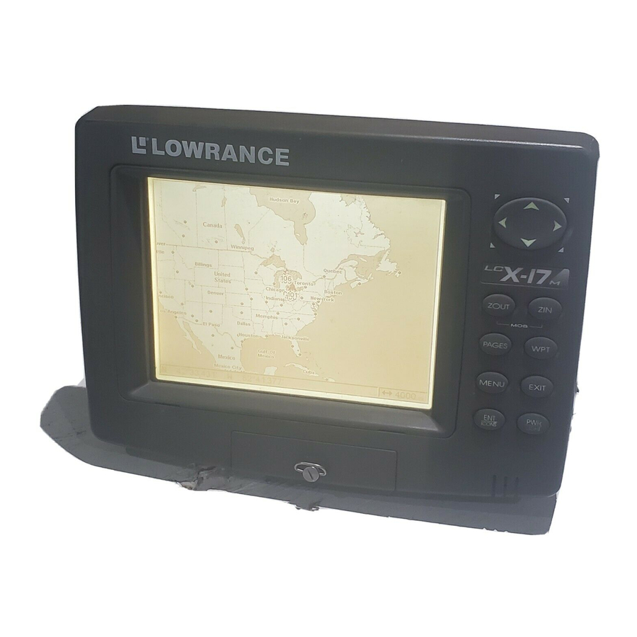
Quick Reference on page 55. Keyboard MMC drawer LCX-17M sonar/GPS unit, front view, showing sonar screen, keyboard and access door for the MMC compartment. 1. PWR/LIGHT (Power & Light) – The PWR key turns the unit on and off and activates the backlight. -
Page 8: Power/Lights On And Off
2. PAGES – Pressing this and the ← → arrow keys switches the unit between the four different page screens. (Satellite Status Page, Navigation Page, Map Page and Sonar Page.) Each page represents one of the unit's major operation modes. 3. -
Page 9: Main Menu
Main Menu The unit has a Main Menu, which contains some function commands and some setup option commands. The instructions in this section will deal only with sonar functions, the basic commands that make the unit show sonar signals on your screen. This unit will work fine right out of the box with the factory default settings. -
Page 10: Satellite Status
destination waypoint, Point of Interest or map cursor location; or after you reach the end of a route or trail. Sonar Setup command: sets various sonar options. GPS Setup command: sets various GPS receiver options. System Setup command: sets general configuration options. Sun/Moon Calculations command: finds the rising and setting time of the sun and the moon. -
Page 11: Navigation
No matter what Page you are on, a flashing current position indicator/question mark symbol and flashing GPS data displays indicate that satellite lock has been lost and there is no position confirmed. WARNING: Do not begin navigating with this unit until the numbers have stopped flashing! Satellite Status Page. -
Page 12: Sonar
always at the top of the screen. The arrow in the center of the screen is your present position. It points in the direction you're traveling. Map Page, showing position on Bull Shoals Lake, Arkansas. The full map option (left). Map with sonar option (right). Map Page is the default screen that appears when you turn on the unit. - Page 13 Pages Menu, showing sonar chart display option commands (left). Sonar Page in full sonar chart display mode (right). Sonar chart display options (from left) split zoom and split frequency. Sonar chart display options (from left) digital data and FlashGraf.
- Page 14 Sonar Page Menu. Most of these functions are discussed in Sec. 4. Digital data Surface clutter Surface signal overlay Depth scale (depth & temperature) In FasTrack, fish arches show as Fish arches horizontal bars. Zoom bar Structure FasTrack Bottom signal bar graph Sonar Page, showing full sonar chart mode.
-
Page 15: Lcx-17M Sonar Quick Reference
LCX-17M Sonar Quick Reference 1. Mount the transducer, antenna and unit. Connect the unit to electric power and the transducer. (If GPS operation is desired, connect GPS antenna, too.) Make sure the MMC is in. (See complete installation details beginning on page 13.) 2. -
Page 16: Sonar Operations
Sonar Operations As you can see from the quick reference on the previous page, basic operation is pretty easy, right out of the box. If you are a sonar novice, try operating the unit with the factory defaults until you get a feel for how it's working. As you're learning the basics, there is one setting you might want to tinker with from time to time —... - Page 17 Adjusting sensitivity in Auto Sensitivity Mode is similar to manually adjusting a car's speed with the accelerator pedal while cruise control is on. You can tell the car to run faster, but when you let off the gas the cruise control automatically keeps you from running slower than the minimum speed setting.
-
Page 18: Fish Symbols Vs. Full Sonar Chart
The sonar options section discusses Fish I.D., fish alarms and other features in greater detail. If you or a friend has Internet access, you can also learn more about interpreting what you see on your sonar screen. Visit our web site, www.lowrance.com. Be sure to check out the free... - Page 19 Aside from being just plain fun, this program can help you learn both basic and advanced operations without burning boat fuel! Lowrance is the first sonar manufacturer to provide this type of training tool for customers.
- Page 20 A free training emulator is available for your unit on our web site. The emulator works exactly like your real sonar/GPS unit. Using the Sonar Simulator and GPS Simulator features, it allows you to play back sonar logs, run GPS routes and trails, even create real waypoints you can use in the field! You can even take snapshots of the Sonar Chart and print them or e-mail them to friends.
-
Page 21: Section 4: Sonar Options & Other Features
Section 4: Sonar Options & Other Features Material in this section is arranged in alphabetical order. ASP (Advanced Signal Processing) The ASP feature is a noise rejection system built into the sonar unit that constantly evaluates the effects of boat speed, water conditions and interference. -
Page 22: Alarms
Alarms This unit has three different types of sonar alarms. The first is the Fish Alarm. It sounds when the Fish I.D. feature determines an echo is a fish. Another alarm is the Zone Alarm, which consists of a bar on the side of the screen. -
Page 23: Zone Alarm
4. Press ← to ENT|EXIT|EXIT|EXIT. HALLOW LARM NABLED 5. To turn off the alarm, press MENU|MENU|↓ ENT|↓ LARMS ONAR ENT|ENT|EXIT|EXIT|EXIT. LARMS To switch to a different depth setting, open the Sonar Alarms menu and repeat the instructions in step 3 above. To adjust and turn on the deep alarm: 1. -
Page 24: Fish Alarm
← → 4. To set the lower boundary for the Zone Alarm, use to select , then press ↑ or ↓ to move the bottom of the bar to the desired OWER depth. 5. Press |← to . Now, any EXIT EXIT EXIT... -
Page 25: Chart Speed
actual speed, you will enter – 10 in the calibration window. If the sensor is reading 5 percent slower than true speed, you will enter + 5 in the window. A good way to gauge your speed sensor's performance is to compare its reading with the ground speed measured by your unit's GPS functions. -
Page 26: Depth Cursor
If you do experiment with chart speed, remember to reset it to maximum when you resume trolling or moving across the water at higher speed. To change chart speed: 1. From the Sonar Page, press |↓ to MENU HART PEED 2. -
Page 27: Depth Range - Manual
Sonar Page menu with Depth Range command selected (left); The Depth Range Control Scale (right). 2. The Depth Range Control Scale appears. Press ↑ or ↓ to select a different depth range. A black bar highlights the selected range. The shaded numbers can not be selected. - Page 28 Changing the upper and lower limits gives you far greater control over the depth range. This feature lets you "zoom in" the display in almost unlimited combinations. Nearly any segment of the water column, from the surface to the bottom can be shown. This enlarges the sonar targets to best suit your fishing needs and water conditions.
-
Page 29: Fastrack
To turn off upper and lower limits: From the Sonar Page, press |↓ to MENU ENT|EXIT. EPTH ANGE FasTrack This feature automatically converts all echoes to short horizontal lines on the display's far right side. The graph on the rest of the screen continues to operate normally. - Page 30 Does that mean Fish I.D. is broken? No. The feature is simply interpreting sonar returns in a specific way to help take some of the work out of reading the screen. Remember: Fish I.D. is one of the many tools we provide so you can analyze your sonar returns for maximum fish finding information.
-
Page 31: Fishtrack
Fig. 1 B Fig. 1 A Fish symbols appear in surface clutter Many fish Fewer fish arches visible symbols visible Fig. 2 B Fig. 2 A No fish shown Fish arches above structure Figures 1A and 2A (left) show Sonar Page in normal chart mode. Figures 1B and 2B (right) show the same underwater scene with Fish I.D. -
Page 32: Frequency (Change Transducer Frequency)
Symbols with FishTrack depths Sonar Features menu with Fish I.D. Depths selected (left). When the check box to the left is unchecked, the feature is off. Sonar Page showing Fish I.D. symbols and FishTrack depths turned on (right). Frequency (Change Transducer Frequency) (Dual-Frequency Transducers only) A dual-frequency transducer operates with both 200 kHz and 50 kHz. -
Page 33: Grayline
Sonar Features menu with a frequency of 200 kHz selected. To change the frequency setting to 50 kHz: 1. From the Sonar Page, press |↓ to MENU ONAR EATURES 2. Press ↓ to 3. Press to clear the menu. EXIT EXIT To change the frequency setting to 200 kHz: 1. -
Page 34: Hyperscroll
Simulator.) If you have a personal computer and internet access, download our free Sonar Viewer and your unit’s emulator at our web site, www.lowrance.com. That will allow you to replay sonar logs on your personal computer. The Sonar Page menu with the Log Sonar Chart Data command selected (left). -
Page 35: Noise Rejection
To record or log chart data: 1. Press |↓ to MENU ONAR HART 2. To record data using the default settings, press . The menu clears and the Sonar Page title bar shows the name of the file you are recording. - Page 36 To overlay information on your screen: 1. Press |↓ to MENU VERLAY 2. If you have overlay data on your display, you’ll see a list of that data on the overlay data shown menu. To add data select NT TO ADD press .
- Page 37 Overlay Data Shown, with water speed selected (left). Press ENT to access R option (right). Press ENT again to remove item and EMOVE return to the Overlay Data Shown screen. To move overlaid data: You may find it useful to rearrange data floating in your display window.
-
Page 38: Ping Speed & Hyperscroll
The overlay data on this sonar display includes, Depth, Temperature, Ground Speed and the Track the boat is following. NOTE: Some data types can be displayed in only one font size. If that is the case, the Data Size box will not be displayed for that data type. Ping Speed &... -
Page 39: Reset Options
Sonar Menu with Ping Speed command selected (left). The Ping Speed Control Bar (right) at default setting. To change Ping Speed: 1. From the Sonar Page, press |↓ to MENU PEED 2. The Ping Speed Control Bar appears. Press ↑ to increase ping speed; press ↓... -
Page 40: Reset Water Distance
System Setup menu with Reset Options command selected (left). The Reset Options dialog box (right). NOTE: Reset Options does not erase any waypoints, routes, plot trails, or sonar logs. Reset Water Distance The sonar chart's Digital Data display option includes a window that shows distance traveled, called Water Distance ("W Distance"). -
Page 41: Sensitivity & Auto Sensitivity
transducer to the lowest part of the boat. In this example, we will use 3.5 feet. This will entered as a negative 3.5 feet, which makes the depth indicators perform as if the transducer's lower in the water than it really 1. - Page 42 Automatic Sensitivity The default sensitivity mode is automatic. The unit bases the sensitivity level on water depth and conditions. When the unit is in the automatic mode, sensitivity is automatically adjusted to keep a solid bottom signal displayed, plus a little more power. This gives it the capability to show fish and other detail.
-
Page 43: Sonar Chart Mode
To adjust sensitivity in manual mode: 1. First, turn off Auto Sensitivity: from the Sonar Page, press |↓ MENU ENSITIVITY 2. Press ↑ to and the Sensitivity Control Bar appears. ENSITIVITY Press ↓ or ↑ to pick a different sensitivity setting. When it's set at the desired level, press EXIT To turn Auto Sensitivity back on:... -
Page 44: Full Sonar Chart
Pages Menu, showing sonar chart display options. Full Sonar Chart This is the default mode used when the unit is turned on for the first time or when it's reset to the factory defaults. The bottom signal scrolls across the screen from right to left. Depth scales on the right side of the screen aid in determining the depth of targets. -
Page 45: Split Zoom Sonar Chart
Split Zoom Sonar Chart A split chart shows the underwater world from the surface to the bottom on the right side of the screen. The left side shows an enlarged version of the right side. The zoom range shows at the bottom left corner of the screen. -
Page 46: Digital Data/Chart
3. The Sensitivity Control Bar appears. Press ↓ to decrease sensitivity; press ↑ to increase sensitivity. When it's set at the desired level, press . (When you reach the maximum or minimum limit, a tone sounds.) EXIT The Split Frequency Sonar Chart page allows you to adjust sensitivity separately for each window. -
Page 47: Flashgraf
Trip Calculator, Time, Sonar and Miscellaneous Data. You can select items from any of these categories for display in any data box. The category divisions are only there to help you sort through the information. To change information displayed in a data box: On the page with the digital data box you wish to change, press |↓... -
Page 48: Map With Sonar Split Screen
show weaker targets as lighter shades. The bottom depth is shown as a black bar across the outer circle. You can adjust the size of the chart and the flasher windows by using the Resize Window command, which is described on page 109. Surface clutter Bottom signal... -
Page 49: Sonar Simulator
Sonar Simulator This unit has a built-in simulator that lets you run it as if you were on the water. All sonar features and functions are useable. When in simulator mode, you will see the chart file name in the Sonar Page title bar and a play symbol will flash on and off at the right end of the title bar. -
Page 50: Stop Chart
Tip: The Sonar Simulator can use sonar charts recorded (logged) on a MMC card. (To see how, read the entry in this section on Log Sonar Chart Data.) To play back a sonar chart, make sure the MMC containing the chart is installed, then: 1. -
Page 51: Surface Clarity
Sonar Menu with Stop Chart command selected. Surface Clarity The markings extending downward from the zero line on the chart are called "surface clutter." These markings are caused by wave action, boat wakes, temperature inversion and more. The surface clarity control reduces or eliminates surface clutter signals from the display. -
Page 52: Upper And Lower Limits
Surface clutter In the illustration on the left, Surface Clarity is turned off. The view on the right shows Surface Clarity set on high. Upper and Lower Limits See the entry in this section for Depth Range - Upper and Lower Limits Zoom &... -
Page 53: Zoom Pan
Zoom Pan Your unit has the handy ability to quickly zoom in on any portion of the water column with just the touch of an arrow key. The Zoom Pan feature lets you rapidly move the zoomed area up and down to different depths. By "pointing"... - Page 54 Notes...
-
Page 55: Section 5: Sonar Troubleshooting
Section 5: Sonar Troubleshooting If your unit is not working, or if you need technical help, please use the following troubleshooting section before contacting the factory customer service department. It may save you the trouble of returning your unit for repair. For contact information, refer to the last page, just inside the back cover of this manual. - Page 56 This causes the sonar to automatically increase its Discrimination or noise rejection feature. This can cause the unit to eliminate weaker signals such as fish or even structure from the display. 3. The water may be deeper than the sonar's ability to find the bottom. If the sonar can't find the bottom signal while it's in the automatic mode, the digital sonar display will flash continuously.
- Page 57 NOISE A major cause of sonar problems is electrical noise. This usually appears on the sonar's display as random patterns of dots or lines. In severe cases, it can completely cover the screen with black dots, or cause the unit to operate erratically, or not at all. To eliminate or minimize the effects of electrical noise, first try to determine the cause.
- Page 58 Notes...
-
Page 59: Section 6: Basic Gps Operations
Quick Reference on page 111. Keyboard MMC drawer LCX-17M sonar/GPS unit, front view, showing sonar screen, keyboard and access door for the MMC compartment. 1. PWR/LIGHT (Power & Light) – The PWR key turns the unit on and off and activates the backlight. -
Page 60: Power/Lights On And Off
Navigation Page, Map Page and Sonar Page.) Each page represents one of the unit's major operation modes. 3. MENU – Press this key to show the menus and submenus, which allow you to select a command or adjust a feature. This also accesses search functions for streets, intersections, addresses and highway exits. - Page 61 will deal only with functions and basic commands that make the Unit do something. The unit will work fine for these lessons right out of the box with the factory default settings. But, if you want to learn about the various options, see Sec. 8, System Setup and GPS Setup Options. You can access the Main Menu from any of the four Page screens by pressing .
-
Page 62: Sonar Page
Trip Calculator command: shows trip status and statistics. Timers command: controls the up timer, down timer and alarm clock settings. Browse MMC Files command: this allows you to view the installed MMC card and the files it contains. Pages The unit has four Page displays that represent the four major operating modes. - Page 63 WARNING: Do not begin navigating with this unit until the numbers have stopped flashing! Satellite Status Page. Left view indicates unit has not locked on to any satellites and does not have a fix on its position. Right view shows satellite lock-on with a 3D position acquired (latitude, longitude and altitude), and WAAS reception.
-
Page 64: Navigation Page
The Satellite Status Page has its own menu, which is used for setting various options. (Options and setup are discussed in Sec. 8.) To access the Satellite Status Page menu, from the Status Page, press MENU Navigation Page This screen has a compass rose that not only shows your direction of travel, but also the direction to a recalled waypoint. - Page 65 When navigating to a waypoint, the Navigation screen looks like the following figure. Your ground speed, track, distance and bearing to waypoint, and course are all shown digitally on this screen. Current track or Course line (dotted) heading, shown in degrees Bearing arrow Compass...
-
Page 66: Map Page
on the Navigation Page screen (and the Map Page screen) as a line. The cross track error range is shown on the compass rose as a wide, white, corridor enclosing the course line. The outer edges of this white corridor represent lines that show the current cross track error range. The default for the cross track error range is 0.20 miles. - Page 67 Far left, Map Page opening screen. Center, zoomed to 100 miles and right, zoomed to 15 miles. The Over Zoomed notice in the top left corner means you have reached the map’s detail limits for the area. Zooming in any closer will reveal no more map details because a custom map has not been loaded on the MMC.
- Page 68 MapCreate custom maps include massive amounts of information not found in the background map. MapCreate contains: Points of Interest database, all the minor roads and streets, all the landmark features (such as summits, schools, radio towers, etc.); more rivers, streams, smaller lakes and ponds and their names.
- Page 69 Page category. To access , press |← or→ to |↓ to PAGES THEM Option| EXIT Digital Data map page (left); Two Position Formats page (right). Pages Menu with Two Maps option selected (left). Map Page with two map windows (right). The left map is active. In pages that have two major windows (such as two maps) you can toggle back and forth between the two windows by pressing This...
- Page 70 The Two Maps page with one window stacked on top of the other. 3. To change the window size again or revert back to the original display, just follow the steps above. (Most dual-window displays use half the screen for each window by default.) You can also use the Reset Options command to revert to the factory default.
-
Page 71: Gps Quick Reference
GPS Quick Reference Start outdoors, with a clear view of the open sky. As you practice, try navigating to a location at least a few blocks away. While you're learning, navigation in too small an area will constantly trigger arrival alarms. 1. -
Page 72: Find Your Current Position
Find Your Current Position Finding your current position is as simple as turning the unit on. Under an unobstructed sky, the unit automatically searches for satellites and calculates its position in approximately one minute or less. If for some reason satellite acquisition takes longer, you may be inside a structure or vehicle or in terrain that is blocking signal reception. -
Page 73: Selecting Any Map Item With The Cursor
Now that you've seen how the unit can find where you are, let's search for something somewhere else. Searching is one of the most powerful features in the Lowrance GPS product line. In this example, we'll look for the nearest fast-food restaurant. For more information on different types of searches, refer to Sec. - Page 74 Category Selection menu (left) and list of the nearest restaurants (right). You could select the nearest restaurant at the top, but we have chosen a restaurant further down the list. Press ENT. The POI information screen appears. This is how you can use the unit as a business phone directory! If you wanted to navigate there, you could press since the...
-
Page 75: Set A Waypoint
Map screen showing the result of a restaurant search. 7. To clear the search and return to the last page displayed, press . (Before you completely exited out of the Search menus, you EXIT EXIT could have gone looking for another place.) NOTE: Search works from mapping and POI data loaded in the unit. - Page 76 Fig 1. Fig 2. Fig 3. Fig 4. Sequence for setting a waypoint. Fig. 1: While traveling, press WPT twice to call up the Find Waypoint screen (Fig. 2) and set a point. Fig. 3: A message says the waypoint has been saved. Fig. 4: vehicle continues on its way;...
-
Page 77: Navigate To A Waypoint
Create Waypoint by Entering a Position 1. Press |→ to column|↓ to UBCATEGORY 2. Press ↓ to |→ to NTERED OSITION REATE 3. Press → to . Enter the latitude by pressing ↑ or ↓ to ATITUDE → change the first character, then press to the next character and repeat until the latitude is correct. -
Page 78: Set Man Overboard (Mob) Waypoint
Waypoint Off course Course range, set line at 0.20 mile Destination name Trail line Navigation Page, navigating toward waypoint 001. Set Man Overboard (MOB) Waypoint One of boating's most terrifying events is having a friend or family member fall overboard. It's particularly dangerous at night or if you're out of sight of land. -
Page 79: Navigate To Cursor Position On Map
Navigating to Man Overboard: Navigation Page, left, and Map Page, right. The victim is astern of the vessel; the GPS shows which direction to steer to for the rescue. The man overboard position is also stored in the waypoint list for future reference. -
Page 80: Navigate To A Point Of Interest
Navigate to cursor. In this example, the town of Oologah, Oklahoma has been selected. 3. Press and the unit will begin navigating to the cursor MENU|ENT location. The Map Page will display a course line from your current position to the cursor position. -
Page 81: Creating And Saving A Trail
earlier in this section or turn to Sec. 9, Searching, for detailed instructions on POI searches.) After you have looked up an item with the Find Waypoint command, → use the to make sure the command is highlighted at the top of the screen, then press . -
Page 82: Displaying A Saved Trail
↓ 2. Press to the active Trail Name| → ↓ 3. Press then . This unchecks the Active option. CTIVE 4. To return to the previous page, press . As you EXIT EXIT EXIT EXIT left the Edit Trail menu, you will notice a new trail was started with a new sequential number. -
Page 83: Navigating Trails
To turn off trail display: 1. Press MENU|MENU|↓ RAILS 2. Press ↓|↓ to enter the Saved Trail list, then use ↑ or ↓ to select the desired Trail Name| 3. Press ↓ → to . To return to the previous page, press ISIBLE EXIT EXIT... - Page 84 1. Press MENU|MENU|↓ RAILS 2. Press ↓ to enter the Saved Trail list, then use ↑ or ↓ to select the desired Trail Name| 3. Press → to |↓ to ELETE RAIL AVIGATE 4. Press ↓ to . The unit begins showing navigation AVIGATE information along the trail.
- Page 85 On the Map Page, a course line represents the trail you are navigating. The bearing arrow on the compass rose points to the next waypoint on the trail. As you travel, the arrival alarm will go off when you near a trail waypoint, and the bearing arrow on the compass rose will swing around and point to the next trail waypoint.
-
Page 86: Navigate A Back Trail (Backtrack, Or Reverse)
Navigate a Back Trail (backtrack, or reverse) 1. Press |↓ to MENU MENU RAILS 2. Press ↓|↓ to enter the Saved Trail list, then use ↑ or ↓ to select the desired Trail Name| → 3. Press |↓ to ELETE RAIL AVIGATE 4. - Page 87 |↓ to and the following screen ETUP RANSFER appears. The Transfer My Data submenu asks if you want to save data to the MMC or load data from the MMC into the unit's memory. 2. The Transfer My Data menu includes a message which tells you if a MMC is present or not.
-
Page 88: Cancel Navigation
4. Loading to unit memory: There may be more than one GPS Data File (*.USR) on the card. To select a file, press to activate the MMC Card selection box, use ↓ or ↑ to highlight the file, then press Next, press ↓... -
Page 89: Section 7: Advanced Gps Operations
Section 7: Advanced GPS Operations Find Distance From Current Position 1. While on the Map Page press: MENU|↓ ISTANCE 2. To find the distance to a specific location, center your cursor over the position. A rubber band line appears, connecting your current position to the cursor's location. -
Page 90: Create Icon On Map
Icons are similar to waypoints, but they do not store as much information. You can't use a menu to navigate to icons like you can with waypoints. But, you can use the map cursor and navigate to any icon on the map. You can create an icon at the cursor position on the map, or at your current position while you are navigating. -
Page 91: Navigate To An Icon
Delete icons menu. The Delete All Icons command will ask if you are sure. Press ← to . All icons will be deleted from the map. The Delete by Symbol command will launch the Select Symbol menu. Press ← or ↑ or → or ↓ to select the icon symbol to delete, then press . -
Page 92: Create And Save A Route
Create and Save a Route You have the option of creating and editing a route in the unit, or you can make a route on your computer with our MapCreate 6 software. PC-created Routes MapCreate is the easiest method for preparing a route, simply because your PC's larger screen, keyboard and mouse are easier to manipulate than the gimbal-mounted unit. - Page 93 Edit Route menu (left). Edit Route Waypoints menu (right) with Add From Map command selected. 3. Use the Zoom keys and arrow keys to move the map and cursor until the cursor is centered on the spot where you want your route to begin. 4.
-
Page 94: Delete A Route
5. Move the cursor to the next point in the route, a spot where you need to turn or change direction, and press to set the next waypoint. 6. Repeat step five until the route reaches the destination. 7. To save your route, press . -
Page 95: Navigate A Route
Edit Route Waypoints menu. 3. Use ↓ and ↑ to select a command from the Edit Route Waypoints menu and press . Add From Map lets you insert a waypoint in the route by clicking on a map location with the cursor. Add Waypoint calls up the Waypoint list so you can insert a waypoint. -
Page 96: Navigate A Route In Reverse
Figure 2. Figure 1. Figure 3. Figure 4. Navigating along a route: Fig. 1 shows the Navigation Page at the start of a route, heading straight for the first waypoint (Wpt 1). In Fig. 2, the traveler has arrived at Wpt 3; the arrival alarm has been triggered and the bearing arrow on the compass rose is turning to point toward Wpt 4, off to the east. -
Page 97: Trails
Trails Delete a Trail This is the command used to delete a trail: Press |↓ to MENU MENU → |↓ to trail name| |← to RAILS ELETE RAIL Tip: You can also delete all trails at once: 1. Press |↓ to MENU MENU RAILS... -
Page 98: Utilities
correct. Press , then to return to the previous EXIT EXIT EXIT EXIT page display. Edit Trail Menu with Pattern option selected (left). Edited trail with dotted line pattern (right). Utilities Utilities are useful tools for traveling or for outdoor activities. Alarm Clock To get to the alarm clock menu: press |↓... -
Page 99: Edit A Waypoint (Name, Symbol, Position)
← 2. Press |↓ to . To return to the ELETE AYPOINT previous page and clear the cursor, press EXIT To delete all waypoints at one time: press |↓ to MENU MENU YSTEM |↓ to |← to . To return ETUP ELETE AYPOINTS... -
Page 100: Set A Waypoint By Projecting A Position
1. Press |→ to column|↓ to UBCATEGORY 2. Press ↓ or ↑ to |press → to VERAGE OSITION REATE 3. Wait while the unit takes points to average for the position. (The greater the number of points, the greater the accuracy.) When the desired number of points accumulates, press to create and save the waypoint. -
Page 101: Section 8 System & Gps Setup Options
Section 8 System & GPS Setup Options Alarms This unit has several GPS alarms. The factory default setting has all the alarms turned on. You can turn the alarms off and on and change their distance settings. An arrival alarm also can be set to flash a warning message and sound a tone when you cross a preset distance from a waypoint. -
Page 102: Auto Satellite Search
4. When your adjustments are finished, return to the last page displayed by repeatedly pressing EXIT. IMPORTANT ALARM NOTES: Anchor Alarm - The anchor alarm may be triggered even when you're sitting still. This typically happens when using small (less than 0.05 mile) anchor alarm ranges. -
Page 103: Communications Port Configuration
Main Menu (left); MMC File Browser (right). Communications Port Configuration The unit has two NMEA 0183 version 2.0 compatible communication ports, or com ports for short. The Com Port Menu, which is accessed from the System Setup Menu, allows you to configure the communications ports to send or receive data to another electronic device, such as an autopilot. -
Page 104: Coordinate System Selection
2. Press ↓ to |↓ to NMEA OMMUNICATIONS ONFIGURE 3. A menu appears showing the prefixes of the available NMEA sentences. A check mark next to a prefix means the prefix is in use. Use ↑ ↓, → ← to select a prefix, then press to turn off the prefix. -
Page 105: Map Fix
on this unit. Your position and datum in use determines which one to use. If you use standard, and your position is off significantly, then try the alternate. NOTE: When the position format is changed, it affects the way all positions are shown on all screens. - Page 106 latitude/longitude lines must be parallel with the edge of the map. USGS maps are parallel, others may not be. Also, this works better with smaller scale maps.) The reference position can be anywhere on the map, but the closer it is to your location, the smaller the numbers you'll have to manipulate.
-
Page 107: Customize Page Displays
Customize Page Displays Several page display options have customizable data boxes to provide constant on-screen information. The various data available from your unit are divided into categories in the Data Viewer menu. These categories include GPS Data, Navigation, Trip Calculator, Time, Sonar Data and Miscellaneous Data. You can select items from any of these categories for display in any data box. -
Page 108: Gps Simulator
GPS Simulator The GPS simulator lets you use the unit as if you were outdoors navigating somewhere. It's a great way to practice using your unit. You can set the starting location by entering latitude or from a stored waypoint, map place or POI location ( command). -
Page 109: Hide Gps Features
2. Set to zero. Select command and press ENT, PEED TEER WITH RROWS which turns on the simulator and returns you to the Map Page 3. Begin navigating along the trail/route. (If you are close enough to the first waypoint, the arrival alarm will usually go off as soon as navigation begins. -
Page 110: Map Auto Zoom
Map Auto Zoom This receiver has an auto zoom feature that eliminates much of the button-pushing characteristic of other brands of GPS receivers. It works in conjunction with the navigation features. First, start navigation to a waypoint. (See the waypoint section for more information on navigating to a waypoint.) Then, with the auto zoom mode on, the unit zooms out until the entire course shows, from the present position to the destination waypoint. -
Page 111: Map Boundaries
Map Boundaries . Press ↓ to From the Map Page, press |↓ to MENU . With the option highlighted, press to check it (turn OUNDARIES on) or uncheck it (turn off.) After the option is set, press EXIT|EXIT return to the page display. Fill Water With White Press ↓... -
Page 112: Map Detail Category Selection
All datums are named. The GPS system is based on the WGS-84 datum, which covers the entire world. Other datums may also cover the entire world, or just a small portion of it. By default, your unit uses the WGS-84 datum. It, however, can show your position using one of 191 different datums. -
Page 113: Map Orientation
Map Menu (left); Map Categories Drawn Menu (right). Map Orientation By default, this receiver shows the map with north always at the top of the screen. This is the way most maps and charts are printed on paper. In Track Up mode, map shows "N" and arrow to indicate north. Map orientation is shown in north up (left) and track up (right). -
Page 114: Navionics Charts
Map Orientation menu with the North Up map option selected (right). Navionics Charts Your unit can display Navionics electronic charts on MMCs. They work just like a MapCreate custom map on a MMC. Entrance to Chesapeake Bay in a MapCreate 6 custom map with a 10- mile zoom (left). -
Page 115: Port Information
These figures show menu sequence (from left to right) for selecting a Navionics chart for the South Chesapeake Bay area. 3. To turn off a Navionics chart, from the Map Page, press MENU|↓ ↑ ↓ . Use to select ENT|→ AVIONICS HOICE , then press... -
Page 116: Tidal Current Information
3. To scroll through the Service Categories window: press then use ↑ ↓ to see the types of services available. As you highlight a different category, the list in the lower window changes. To return to the Map Page, press EXIT|EXIT. - Page 117 Tidal Current Station icon Pop-up in animated name box mode Cursor lines Navionics chart showing Tidal Current Station icon selected by cursor. In this example, the tidal current is in flood but it's about to enter the slack water stage. The current is flowing to the west at 0.1 mph. Current Information screen.
-
Page 118: Tide Information
You can look up tidal current data for other dates by changing the month, day and year selection boxes. To select another date: → ← 1. Use to highlight month, day or year, then press ↑ ↓ 2. Use to select the desired month, day or year, then press To clear the information screen, press EXIT Tide Information... -
Page 119: Pop-Up Help
Tide Information screen. The Tide Information screen displays daily tidal data for the station at the present time. The graph at the top of the screen is an approximate view of the tidal range pattern for the day, from midnight (MN), to noon (NN) to midnight (MN). -
Page 120: Reset Options
System Setup menu (left) with Pop-up Help command highlighted. The example on the right shows the Pop-up Help message for the Screen command, located on the Map Menu. Reset Options To reset all features to their factory defaults: ↓ to Press |↓... -
Page 121: Set Language
Screen Command (left) and Screen Menu with Contrast selected, (right). To adjust the display's brightness: Press ↓ to . Press → or ← to move the bar. The left end of the RIGHTNESS scale is minimum contrast; the right end is maximum contrast. To adjust the screen's display mode: Press ↓... -
Page 122: Set Local Time
Set Local Time Using the correct local time setting is handy when estimating local arrival time while navigating. Also, the time and date are saved when a waypoint is created. To access the Set Local Time menu, you must first acquire your position. -
Page 123: Show Waas Alarm
Software Version Information From time to time, Lowrance updates the operating system software in some of its products. These software upgrades are usually offered to customers as free downloads from our web site, www.lowrance.com. -
Page 124: Track Smoothing
Sounds command (left); The Sounds menu (right). Once in the Sounds menu To set Key Press Sounds: With the option highlighted, press check it (turn on) or uncheck it (turn off). After the option is set, press to return to the page display. EXIT|EXIT Press ↓... -
Page 125: Trail Options
Track Smoothing option, turned on. Trail Options There are several options you can use with trails. Some affect all trails, other options can be applied to a particular trail. You can change the way trails are updated and the way they’re displayed. Trails also may be hidden, created or deleted in the trail menu. -
Page 126: Delete Trail
Update Trail Criteria (Auto, Time, Distance) The options are automatic, time or distance. When it's in the default automatic mode, the unit doesn't update the plot trail while you're traveling in a straight line. Once you deviate from a straight line, the unit "drops"... -
Page 127: New Trail
Edit Trail menu. New Trail To manually start a new trail in the Trails Menu make sure RAIL highlighted and press ENT|EXIT. Trail Visible/Invisible and Other Trail Options The name, maximum number of points in the trail, activity, and visibility are all changed on the Edit Trail menu screen. The Active setting determines whether or not the unit is recording new points for a particular trail. - Page 128 System Setup Menu (left); Units of Measure Menu (right). To set Speed/Distance Unit of Measure: Press ↑ or ↓ to change the Speed/Distance, then press After the option is set, press ENT. to return to the page display. EXIT|EXIT|EXIT To set Heading: Press ↑ or ↓ to change the heading type, then press After the option is set, press to return to the page ENT.
-
Page 129: Section 9: Searching
Section 9: Searching NOTE: The background map loaded in your unit lets you search for U.S. Interstate Highway exits and exit services, as well as some land features, including cities and lakes. For a full set of searchable land features, including landmarks, streets, addresses and Points of Interest, you must load your own high-detail custom map produced with our MapCreate 6 software. - Page 130 Find Address Menu. press ↑ or ↓ to change the first number, then To enter an address press → to move the cursor to the next number and repeat until the number is correct, then press ENT. press ↓ to To enter a street name There are two ENT.
- Page 131 NOTE: We recommend you do not enter a city name unless the list is too long to search through. The unit actually can search quicker when you don’t enter a city name. Find city field (left); search in particular city only option (center); Find City by name (right).
-
Page 132: Find Any Item Selected By Map Cursor
the map, press The POI's Waypoint Information window WPT. appears, with the Go To Waypoint command highlighted. If you want to go ahead and navigate to the POI address, just press EXIT. Map Page showing location of the address on the map, highlighted by cursor (left). - Page 133 Find Highway Exits command (left) and Find Exit menu (right). 2. First, select a highway name by pressing , which calls up the Find by Name menu. There are two highway search options A. You can spell out the highway name in the top selection box. Press ↑ or ↓ to →...
- Page 134 Find Exit menu, with an exit selected in the Exit List. 4. In the Exit Information screen you have two choices. A. Press → navigate or "go to" the exit. B Press to find the exit on the map Go To Exit option (left); Find On Map option (right). Tip: You can also look up some additional information on the services ↓...
Need help?
Do you have a question about the LCX-17M and is the answer not in the manual?
Questions and answers