Table of Contents
Advertisement
Quick Links
Advertisement
Table of Contents

Related Manuals for Mean Well PB-1000


Summary of Contents for Mean Well PB-1000
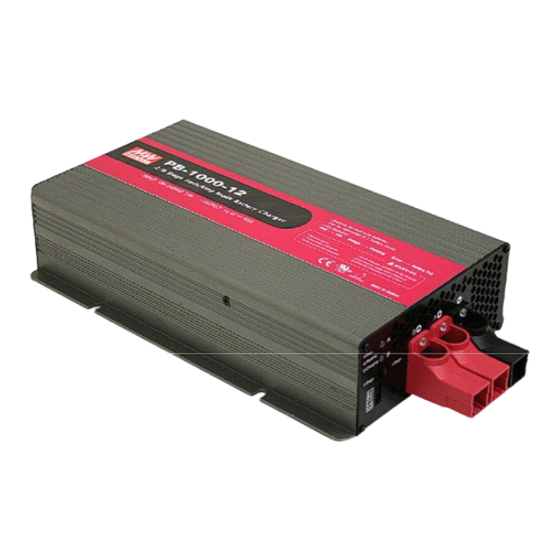
- Page 1 PB-1000 Instruction Manual...
-
Page 2: Table Of Contents
PB-1000 Instruction Manual Index 0.Product description................. 1.Notes on operation ................. 2.Front and back panel ..................................3.Derating curve 3.1 Charging current VS temperature ........................4.Function description for CN100 ..................5.LED Indication 6.Explanation of operation logic (charging stages) ........6.1 2 stage charging (flick switch to "2" stage) ......... -
Page 3: Product Description
0.Product description PB-1000 is MW's next generation smart charger. It has many of the protective features th a t co n su mer s wo u ld like to h ave in a cha rg er inclu din g ba tte ry misco nne ctio n (wrong voltage), reverse polarity, battery disconnection or not connected, and battery failure analysis. -
Page 4: Derating Curve
Battery B Battery A Common Positive Positive Negative Indi cator 2/3/8 stag e Stage 8/3/2 se lect io n s witc h Func tion Connec t or WARNING : Battery B Battery A Please check batter y polarity before Figu re 2.2 Ba ck P anel connection Assemb ly guideline s: 1.The ch arger should be turned OFF prior to battery connection. -
Page 5: Led Indication
Gr e en to s how a fu ll ch a rg e . C h an n el A wil l tur n OF F w hile cha rgin g com mence at Channel B. After the battery at channel B is fully charged, PB-1000 will turn OFF its outputs. -
Page 6: Stage Charging (Flick Switch To "3" Stage)
2 Constant Current Constant Voltage Battery Full Orange Green Color of LED State PB-1000-12 PB-1000-24 PB-1000 -48 Constant 34.7A 17.4A Current 14.4V 28.8V 57.6V boost Fig ure 6.1 2 stag e ch arging curve Ex planation for 2 stag es charging curve... -
Page 7: Stage Charging (Flick Switch To "8" Stage) 3
A float voltage of 2.3V per cell is provided so that the battery can maintain full charge. *For applications that u tilize the charger (PB-1000) to charge batteries and su pply. System po wer simultaneously(e.g. UPS system), pl ease select "3 sta ge" chargin g for the best use of the c harger. - Page 8 ◎ A dva ntag e of floa t an d ma intain s tage : Aft er LED t urns gre en, m ainten ance charge is provided so the battery is always in a full state. User will have access to a full battery wh enever it is disconnected from the charger.
-
Page 9: Function Description
(5)Stage 5 (analysis): The cha rger will sto p ch argi ng fo r 2 m inu tes to de term ine battery sta tus. If th e battery voltage is higher than 2.1 V per cell, the battery is d etermined as OK and will move on to stage 6. -
Page 10: Two Battery Banks
7.4 Tw o battery banks The cha rge r ca n be hoo ked up t o tw o ba ttery ba nks (A a nd/o r B) . Co n nec t th e battery bank(s) as below. If you are connecting 2 battery banks at the same time, kee p in mind that it m ust sha re a com mon ground . -
Page 11: Reverse Polarity Protection
C hargin g mod e Switch Slide right 2 sta ge ch arging Stage 8/3/2 Mid dle 3 sta ge ch arging Slide left 8 sta ge ch arging Stage 8/3/2 Ba ttery B Batte ry A 7.6 Reverse polarity p rotection With built-in battery reverse polarity detection circuit. -
Page 12: Temperature Compensation
10 Temperature compensation Temperature sensor which comes with the charger can be connected to the unit to allow temperature compensation of the charging voltage. If the tem perature sensor is not used, the ch arger can still w ork normally. Stage 8/3/2 The t emperature senso r can either... -
Page 13: Series And Parallel Connection Of Batteries
Output cables are too thin period wire gauge If you are not able to clear the failure condition, plea se contact Mean Well o r any o f our distrib utors fo r repair service . WARNING : This is a class A product. In a domestic environment this product ma y ca u se ra di o int e rfe ren ce in wh ic h c a se the u se r ma y be required to take ade quate measures.
Need help?
Do you have a question about the PB-1000 and is the answer not in the manual?
Questions and answers