Table of Contents
Advertisement
Advertisement
Table of Contents

Subscribe to Our Youtube Channel
Related Manuals for Mean Well DBU-3200 Series


Summary of Contents for Mean Well DBU-3200 Series
- Page 1 DBU-3200 Instruction Manual...
-
Page 2: Table Of Contents
DBU-3200 Instruction Manual Index 0. roduct Description ................. 1.Notes on Operation .......................... 2.Mechanical Design and Installation Procedure 3.Derating Curve ..................3.1 Charging Current vs Temperature ............. 3.2 Charging Current vs Input Voltage ............ 4.Pin Assignment ..................5.LED Indication ..................6.Explanation of Operation Logic ............... -
Page 3: Roduct Description P
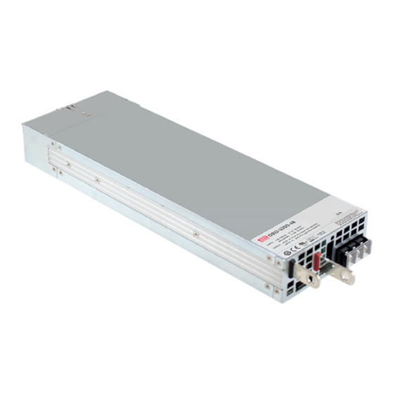
0.Product Description DBU-3200 is MEAN WELL's new generation intelligent battery charger with high power density. Different battery brands and types (lead acid batteries, such as flooded, Gel, AGM, and so on, or lithium-ion batteries, such as lithium iron, lithium manganese, and so on) may require different charging curves and protection mechanisms for batteries, DBU-3200 is able to be accommodated through the communication interface;... -
Page 4: Derating Curve
Installation Procedure: Please make sure the charger is OFF before connecting the battery to the output terminal. Choose a cable with suitable wire gauge according to the charging current to connect between the charger and the battery. Battery polarity must be connected correctly:Terminal(+) to Battery(+); Terminal(-) to Battery(-), and take notice that the positive and negative ends are not shorted. -
Page 5: Led Indication
CN500 Pin No. Function Description Differential digital signal for parallel control. Differential digital signal for parallel control. Negative output voltage signal. -V (Signal) It is for local sense; and certain function reference; it cannot be connected directly to the load. Serial clock used in the PMBus interface. - Page 6 Explanation for 3 stage charge curve : (0) Initial stage (battery analysis) Check battery voltage level to see whether there is a battery connected. : (1) Stage 1 (constant current) A constant current is provided so that the battery can be quickly charged to 2.4V per cell.
-
Page 7: Pmbus And Canbus Communication Interface
1. Output voltage, current and internal temperature Alarm and status anufacturer' and model data 4 Read/write of charge curve settings For further CANBus information Please contact MEAN WELL for detail. PMBus Device Addre sing and Charge Mode Selection ◎ Each DBU 3200 unit should have their unique and own device address to communicate over the PMbus. - Page 8 Charging Curve When it is opted for charging curve, D0 set to 0, charging curve function is enabled with additional PMBus commands. There are 4 built-in charging curves, “default” curve, one pre-defined curve for “gel battery”, one pre-defined curve for “flooded battery” and one pre-defined curve for “AGM battery”. Each curve can be selected by Command B4h CURVE_CONFIG.
- Page 9 Command Command Transaction # of data Description Code Name Type Bytes OPERATION R/W Byte Remote ON/OFF control ON/OFF function configuration ON_OFF_CONFIG Read Byte Capabilities of a PMBus device CAPABILITY Read Byte Define data format for output voltage VOUT_MODE R Byte (format: Linear, N= -9) Output voltage setting value VOUT_COMMAND...
- Page 10 Command Command Transaction # of data Description Code Name Type Bytes Constant current setting value of charging curve CURVE_CC R/W Word (format: Linear, N= - ) 2 Constant voltage setting value of charging curve CURVE_CV R/W Word (format: Linear, N= -9) Constant voltage setting value of charging curve CURVE_FV R/W Word...
- Page 11 ◎ Definition of Command B8h CHG_STATUS: Bit7 Bit6 Bit5 Bit4 Bit3 Bit2 Bit1 Bit0 High byte FVTOF CVTOF CCTOF BTNC NTCER EEPER Low byte FULLM Low byte Bit 0 FULLM:Fully Charged 0=NOT fully charged 1=fully charged Bit 1 CCM:Constant Current Mode Status 0=the charger NOT in constant current mode 1=the charger in constant current mode Bit 2...
- Page 12 Note: EEPER When EEPROM Charge Parameter Error occurs, the charger stops charging the battery and the LED indicator turns red. The charger needs to re-power on to re-start charging the battery. NTCER: When Temperature Compensation Short occurs, the charger output will shut down and the LED indicator will turn red.
- Page 13 ◎ Control parameter PMBus command Model Adjustable range Tolerance Default OPERATION 00h(OFF) / 80h(ON) 80h(ON) VOUT_COMMAND (Note. 2) ±0.36V -6 ~ 6V VOUT_TRIM ±0.48V (Note. 2) -12 ~ 12V ±0.36V 18 ~ 30V 28.8V CURVE_CV ±0.48V (Note. 3) 36 ~ 60V 57.6V ±0.36V 18 ~ VBST...
- Page 14 Insert an at least 35msec delay between commands. When there is no any PMBus command detected for 10 sec, the charger restores to the factory default settings, that is operation = ON…etc. please refer to Tabel 8-4. Data format of IOUT_OC_FAULT_LIMIT(46h), CURVE_ICHG(B0h), CURVE_ITAPER(B3h) is as below: (Please refer to PMBus_Specification_Part_II_Rev_1-1 for detailed information) Data format of VOUT_MODE, VOUT_MODE, VOUT_COMMAND, VOUT_TRIM, READ_VIN, R E A D _ V O U T, R E A D _ I O U T, R E A D _ T E M P E R AT U R E _ 1 , R E A D _ FA N _ S P E E D _ 1 ,...
-
Page 15: Function Description
7.1.1 Interpreting Received Values The host system uses the following equation to convert the value received from the PMBus device into a reading of volts, amperes, degrees Celsius or other units as appropriate: 7.1.2 Sending A Value ◎ Please refer to our specifications about PV/PC or SVR Function. 9.Function description Input voltage ◎The... -
Page 16: Temperature Compensation
9 3 . Temperature Compensation Temperature sensor which comes with the charger can be connected to the unit to allow temperature compensation of the charging voltage. If the temperature sensor is not used, the charger can still work normally. PIN15 RTH+ PIN16 RTH- 10.Wiring for battery Select suitable wire guage based on rated charging current. -
Page 17: Series And Parallel Connection
Green after a long charging Output cables are too thin Replace with suitable wire gauge period If you are unable to clarify the problem you are facing, please contact MEAN WELL or any of our distributors for repair service. - Page 18 N o . 2 8 , W u q u a n 3 r d R d . , W u g u D i s t . , N e w Ta i p e i C i t y 2 4 8 , Ta i w a n...
Need help?
Do you have a question about the DBU-3200 Series and is the answer not in the manual?
Questions and answers