Table of Contents
Advertisement
AIR CONDITIONER
INSTALLATION MANUAL
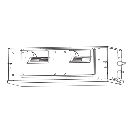
INDOOR UNIT (Duct Type)
For authorized service personnel only.
INSTALLATIONSANLEITUNG
INNENGERÄT (Für Luftkanalsysteme)
Nur für autorisiertes Personal.
MANUEL D'INSTALLATION
UNITÉ INTÉRIEURE (Type conduit)
Pour le personnel agréé uniquement.
MANUAL DE INSTALACIÓN
UNIDAD INTERIOR (Con conductos)
Solo para personal autorizado.
MANUALE D'INSTALLAZIONE
UNITÀ INTERNA (Tipo di condotto)
Ad uso esclusivo del personale autorizzato.
ΕΓΧΕΙΡΙΔΙΟ ΕΓΚΑΤΑΣΤΑΣΗΣ
ΕΣΩΤΕΡΙΚΗ ΜΟΝΑΔΑ (Τύποςαγωγού)
Гια εξουσιοδοτημένο προσωπικό σέρβις.
MANUAL DE INSTALAÇÃO
UNIDADE INTERIOR (Tipo conduta)
Apenas para técnicos autorizados.
РУКОВОДСТВО ПО УСТАНОВКЕ
ВНУТРЕННИЙ МОДУЛЬ (Канального типа)
Для yпoлнoмoчeнного персонала.
KURULUM KILAVUZU
İÇ ÜNİTE (Oluk tipi)
Yetkili servis personeli içindir.
PART NO. 9380441038
Advertisement
Table of Contents

Subscribe to Our Youtube Channel
Related Manuals for Fujitsu INDOOR UNIT Duct Type


Summary of Contents for Fujitsu INDOOR UNIT Duct Type
-
Page 1: Air Conditioner
AIR CONDITIONER INSTALLATION MANUAL INDOOR UNIT (Duct Type) For authorized service personnel only. INSTALLATIONSANLEITUNG INNENGERÄT (Für Luftkanalsysteme) Nur für autorisiertes Personal. MANUEL D'INSTALLATION UNITÉ INTÉRIEURE (Type conduit) Pour le personnel agréé uniquement. MANUAL DE INSTALACIÓN UNIDAD INTERIOR (Con conductos) Solo para personal autorizado. MANUALE D'INSTALLAZIONE UNITÀ... -
Page 2: Table Of Contents
INSTALLATION MANUAL The units are not explosion proof and therefore should not be installed in explosive PART NO. 9380441038 atmosphere. INDOOR UNIT (Duct Type) Never touch electrical components immediately after the power supply has been turned Contents off. Electric shock may occur. After turning off the power, always wait 5 minutes before touching electrical components. -
Page 3: Accessories
21 21 Accessories INSTALLATION WORK Especially, the installation place is very important for the split type air conditioner because WARNING it is very difficult to move from place to place after the first installation. For installation purposes, be sure to use the parts supplied by the manufacturer or 21 11 Selecting an installation location other prescribed parts. -
Page 4: Installation The Unit
21 21 21 Installing hangers 21 21 21 Installation by which service is carried out from the bottom of the Suspend the indoor unit by referring to the following figures. unit 1260 1192 Inlet port 20 or Service more space 500 or more Unit : mm Service access... -
Page 5: Pipe Installation
21 21 41 Mounting the duct Pipe outside diameter [mm (in.)] Thickness [mm] Follow the procedure in the following figure to install the ducts. 6.35 (1/4) Inlet port flange 9.52 (3/8) 12.70 (1/2) 1260 15.88 (5/8) 19.05 (3/4) 1062 41 21 Pipe requirement CAUTION Refer to the Installation Manual of the outdoor unit for description of the length of... -
Page 6: Installing Heat Insulation
41 21 21 Bending pipes 41 41 Installing heat insulation • If pipes are shaped by hand, be careful not to collapse them. • Do not bend the pipes in an angle more than 90°. Install the heat insulation material after performing a refrigerant leak check (see the •... -
Page 7: Electrical Wiring
• INSTALL THE DRAIN PIPE WARNING Use general hard polyvinyl chloride pipe (VP25) and connect it with adhesive (polyvinyl chloride) so that there is no leakage. Do not perform air bleeding. Perform wiring work in accordance with standards so that the air conditioner can be operated safely and positively. -
Page 8: Remote Controller Setting
61 21 21 Connection cable preparation Keep the earth (ground) wire longer than the other wires. Power supply cable Earth (ground) wire or connection cable Control line • Use a 4-core wire cable. Power line Black White How to connect wiring to the terminals. (For strand wiring) *Earth Use crimp-type terminals with insulating sleeves as shown in the figure below to... -
Page 9: Installing The Remote Controller
SW state 71 11 Installing the remote controller Detail Open the operation panel on the front of the remote controller, remove the 2 screws Cannot be used. ♦ indicated in the following figure, and then remove the front case of the remote controller. (Do not change) When installing the remote controller, remove the connector from the front case. -
Page 10: Function Setting
Auto Restart Press the set temperature buttons ( ) to select the setting value. The display flashes as shown to the right during setting value selection. (The setting value is factory-set to “00”.) Function Setting Setting Description Number Value Press the TIMER SET button to confirm the setting. Press the TIMER SET button for a Indoor Room Temperature Sensor Switching Function few seconds until the setting value stops flashing. -
Page 11: Setting The Room Temperature Detection Location
81 41 Setting the room temperature detection location CHECK LIST • The detection location of the room temperature can be selected from the following two Pay special attention to the check items below when installing the indoor unit(s). After examples. Choose the detection location that is best for the installation location. installation is complete, be sure to check the following check items again. -
Page 12: Fan Delay Setting
Set the R.C. address in accordance with the table below. 111 21 Fan delay setting R.C. address DIP switch This setting can be used when the auxiliary heater is mounted. When the operation is stopped when the indoor unit is operating with an auxiliary heater, the operation continues 1 minutes. -
Page 13: I.r. Receiver Unit / Remote Sensor
• Wiring arrangement Option parts External input/output wire Insulated connection Field supply • Connection terminals CN100 Operation status output (White) CLIP CN161 Fresh air control Cable tie (Medium) Connector output (Green) CN160 I.R. receiver unit External electrical • Use 7 pins for I.R. receiver unit cable heater control CN103 Remote sensor... -
Page 14: Error Codes
• Heat Ex. centre temp. ERROR CODES ● ● sensor error ◊ Outdoor unit [Troubleshooting at the remote control LCD] • Heat Ex. Liquid outlet This is possible only on the wired remote control. temp. sensor error [Self-diagnosis] Outdoor temp. sensor ●...
Need help?
Do you have a question about the INDOOR UNIT Duct Type and is the answer not in the manual?
Questions and answers