Table of Contents
Advertisement
AIR CONDITIONER
INSTALLATION MANUAL
For authorized service personnel only.
INSTALLATIONSANLEITUNG
Nur für autorisiertes Personal.
MANUEL D'INSTALLATION
Pour le personnel agréé uniquement.
MANUAL DE INSTALACIÓN
Solo para personal autorizado.
MANUALE D'INSTALLAZIONE
Ad uso esclusivo del personale autorizzato.
ΕΓΧΕΙΡΙΔΙΟ ΕΓΚΑΤΑΣΤΑΣΗΣ
Για εξουσιοδοτημένο προσωπικό σέρβις.
MANUAL DE INSTALAÇÃO
Apenas para técnicos autorizados.
РУКОВОДСТВО ПО УСТАНОВКЕ
Для уполномоченного персонала.
KURULUM KILAVUZU
Yetkili servis personeli içindir.
PART NO. 9379127035-02
Advertisement
Table of Contents

Related Manuals for Fujitsu INDOOR UNIT (Duct Type) AIR CONDITIONER


Summary of Contents for Fujitsu INDOOR UNIT (Duct Type) AIR CONDITIONER
-
Page 1: Air Conditioner
AIR CONDITIONER INSTALLATION MANUAL For authorized service personnel only. INSTALLATIONSANLEITUNG Nur für autorisiertes Personal. MANUEL D'INSTALLATION Pour le personnel agréé uniquement. MANUAL DE INSTALACIÓN Solo para personal autorizado. MANUALE D'INSTALLAZIONE Ad uso esclusivo del personale autorizzato. ΕΓΧΕΙΡΙΔΙΟ ΕΓΚΑΤΑΣΤΑΣΗΣ Για εξουσιοδοτημένο προσωπικό σέρβις. MANUAL DE INSTALAÇÃO Apenas para técnicos autorizados. -
Page 2: Table Of Contents
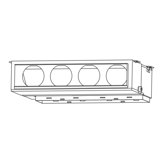
INSTALLATION MANUAL CAUTION PART NO. 9379127035 Read carefully all security information before use or install the air conditioner. INDOOR UNIT (Duct Type) Do not attempt to install the air conditioner or a part of the air conditioner by yourself. Contents This unit must be installed by qualified personnel with a capacity certificate for handling refrigerant fluids. -
Page 3: Accessories
2.3. Accessories Special nut A For suspending the indoor unit (large fl ange) from ceiling WARNING For installation purposes, be sure to use the parts supplied by the manufacturer or other prescribed parts. Special nut B For suspending the indoor unit The use of non-prescribed parts can cause serious accidents such as the unit to fall, (small fl... -
Page 4: Installation Dimension
(3) Leave the space required to service the air conditioner. 3.3.1. Installing the hangers (4) Locate where the air can be distributed evenly throughout the room by the unit. WARNING (5) Install the unit where connection to the outdoor unit is easy. When fastening the hangers, make the bolt positions uniform. -
Page 5: Pipe Installation
3.3.3. Intake duct connection Turn up the insulation around the points to be cut according to the outlet port shape working points so that the insulation does not stick out at the part. Follow the procedure in the following fi gure to the ducts. Unit : mm The air inlet duct can be changed by replacing the intake grille and fl... -
Page 6: Pipe Requirement
Width across Pipe outside Width across flats Thicknesses of Annealed Copper Pipes (R410A) diameter [mm (in.)] of Flare nut [mm] fl ats Pipe outside diameter [mm (in.)] Thickness [mm] 6.35 (1/4) 6.35 (1/4) 0.80 9.52 (3/8) 9.52 (3/8) 0.80 12.70 (1/2) 12.70 (1/2) 0.80 15.88 (5/8) -
Page 7: Installing Heat Insulation
Outlet Drain 4.4. Installing heat insulation Trap air fl ow hose CAUTION GOOD PROHIBITED After checking for gas leaks (refer to the Installation Manual of the outdoor unit), Arrange the drain hose lower perform this section. than this portion. Install heat insulation around both the large (gas) and small (liquid) pipes. Failure to do so may cause water leaks. -
Page 8: Connection Diagrams
(1) Use ring terminals with insulating sleeves as shown in the fi gure below to connect to 6. ELECTRICAL WIRING the terminal block. (2) Securely clamp the ring terminals to the cables using an appropriate tool so that the cables do not come loose. Cable Cable size (mm Type... -
Page 9: Connection Cable Preparation
Simultaneous twin ( 22, 24 type only ) 22,24 model Connection cable After wiring is complete, secure the remote controller cable, transmission cable, with the cable tie and the clamper. Indoor unit Outdoor unit (Primary) Junction box (Local purchase) Indoor unit (Secondary) Control line Detail (a) -
Page 10: Remote Controller Setting
7. REMOTE CONTROLLER SETTING CAUTION When detecting the room temperature using the remote con- Temperature troller, please set up the remote controller according to the sensor following conditions. If the remote controller is not located prop- erly, the correct room temperature will not be detected, and thus abnormal conditions like “not cooled”... -
Page 11: Function Setting
(4) Press the SET TEMP. buttons ( ) to select the setting value. 8. FUNCTION SETTING The display fl ashes as shown to the right during setting value selection. CAUTION Confi rm whether the wiring work for outdoor unit has been fi nished. Confi... - Page 12 (♦... Factory setting) Setting record Function Setting description Setting value • Record any changes to the settings in the following table. number ♦ Setting Setting Value Standard (1) Filter sign Slightly lower control (2) Static pressure Lower control (3) Cooling room temperature correction Warmer control (4) Heating room temperature correction (5) Auto restart...
-
Page 13: Mode Setting
Indoor unit Unit number DIP SWITCH No. CAUTION When select the “Remote controller setting”, if the detected temperature value between the temperature sensor of the indoor unit and the temperature sensor of the remote controller varies signifi cantly, it is likely to return to the control status of temperature sensor of the indoor unit temporarily. -
Page 14: Fresh Air Intake
DIP switch setting (Indoor unit) Standard Simultaneous Simultaneous Set the unit number of each indoor unit using the DIP switches on the indoor unit twin triple pair circuit board. (See the following table and fi gure.) Out door Out door Out door The DIP switches are normally set to make the unit number 00. -
Page 15: Test Run
CAUTION 11. CHECK LIST When removing the cabinet (iron plate), be careful not to damage the indoor unit inter- Pay special attention to the check items below when installing the indoor unit(s). After nal parts and surrounding area (outer case). installation is complete, be sure to check the following check items again. -
Page 16: Customer Guidance
Error display 13. CUSTOMER GUIDANCE Wired remote con- OPERATION TIMER ECONOMY Description Explain the following to the customer in accordance with the operating manual: troller Error lamp lamp lamp code (green) (orange) (green) (1) Starting and stopping method, operation switching, temperature adjustment, timer, air Outdoor unit Heat Ex.
Need help?
Do you have a question about the INDOOR UNIT (Duct Type) AIR CONDITIONER and is the answer not in the manual?
Questions and answers