Table of Contents
Advertisement
Quick Links
Advertisement
Table of Contents

Subscribe to Our Youtube Channel
Related Manuals for Vimar 1960


Summary of Contents for Vimar 1960
- Page 1 Instructions manual 01960 Control panel module for monitor 20550...
- Page 2 Sections index Automation section ................Burglar alarm section .
- Page 3 Section Automation...
-
Page 5: Table Of Contents
Index Introduction . . . . . . . . . . . . . . . . . . . . . . . . . . . . . . . . . . . . . . . . . . . . . . . . . . . . . . . . . . . . . . . . . . . . . . . . 1. -
Page 6: Introduction
Introduction The By-me automated system via the control panel with its Monitor 20550 and Module 01960 provides integrated control of comfort, security, energy saving, climate control and remote control in the residential and commercial sectors . This manual is arranged in a sequence of sections that provide a complete understanding of the By-me system and allow the user to take full advantage of the available features: • Chapter 1 “Main functions”: describes what can be controlled with the By-me system (see page 5);... -
Page 7: Main Functions
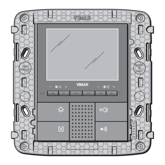
Panic alarm Load control Access control Speaker system ECONOMY REMOTE CONTROL Power management Temperature status Load programming Climate programming Adjustment range Alarm signals Device actuation Scenario activation Intrusion detection alarm system ON/OFF Diagnostics MADE PAT. PEND. ITALY Monitor VIMAR 20550 + Control panel module 01960... -
Page 8: Basic Concepts
Basic concepts 2. Basic concepts. This chapter explains some fundamentally important concepts that are necessary for correctly making full use of the system . Note. Some of the examples contain references to the device codes; for more information, please refer to the instruction sheet for the product concerned. - Page 9 Basic concepts For example, during installation, the actuator could be used to control load A through the push-button of another device, the left push-button to control load B through an actuator, the middle button to control load C through a second actuator and the right button to control load D through a third actuator .
- Page 10 Basic concepts • Connection: logic link between two functional units, which allows a function to be shared (for example: relay actuator and push-button) . • Configuration: operation that can be used to create the logic connection between various functional units (of various appliances) .
- Page 11 Basic concepts To control the switching on of a load from different points, it is sufficient to add more functional units; it is not necessary to modify the wiring . Eikon 20521 Eikon 20521 Eikon 20535 Idea 16961 Idea 16961 Idea 16975 Plana 14521...
- Page 12 Basic concepts • Scenario: a scenario is an exact positioning of the actuators in one or more functional groups that can be called up as preferred from a menu on the control panel or with a button configured for this purpose or with the infrared remote control 01849 .
- Page 13 Basic concepts Each line can be composed of at most 128 devices and needs one or two power supplies depending on the number of devices and the length of the bus. Using line couplers, a number of lines can be connected to each other, up to a maximum of 15 areas x 15 lines;...
-
Page 14: Installation Topology
(pair) that supplies the devices with the power and the signals carrying the digital control and monitoring data . Note. The connecting cable, art. Vimar 01840, is the same as the one used in the burglar alarm bus system and Vimar bus entrance control system. -
Page 15: System Content
• control devices with or without actuators; • actuators, such as relays or regulators for example; Module 01960 must be inserted in the compartment on the back of monitor 20550 in correspondence with the connector bearing the words “CONTROL PANEL” . You are recommended to do this without the devices being powered and checking that, after hooking up the module with the monitor, the mechanical coupling is perfect (all the clamps must be properly tightened) . - Page 16 Installation topology 3.2 Bus system installation. 3.2.1 General rules and system topology. • For the connections use a VIMAR 01840 sheathed and twisted pair (2x0.5 mm , nominal insulation voltage 300/500 V). The wire pair distributes both the power supply voltage (29 V d.c.) and the device control signals, and can be placed inside the same corrugated pipe that carries the electrical mains cables .
- Page 17 • EN 50022 rail devices such as the load control module, GSM communicator, interfaces. • surge protection devices to protect the installation. It is advisable to use a dedicate cable trough for the corrugated tubes that carry the Vimar 01840 cable for the Bus line; however, the ones that carry the mains power cables can also be used .
- Page 18 POWER SUPPLY 250 m 250 m 500 m 3.2.5 Bus installation: summary table. • Installation and system topology: • BUS line cable laid in dedicated cable troughs; can also be placed in the corrugated tubes that carry the mains power cable . • Configurations allowed: • Linear configuration • Star configuration • Mixed configuration • We recommend using junction boxes • Type of cable that can be used: sheathed VIMAR 01840 twisted pair (2x0.5 mm , nominal insulation voltage 300/500 V)
-
Page 19: Description Of Terminals
01998 .U on the side of the monitor 20550 (fig . 3 .3 .2) . - 30-pole PIN-STRIP connector: connector on the monitor side for hooking up the control panel module 01960 with the monitor 20550 (fig . 3 .3 .2) . -
Page 20: Putting The System Into Service
3.4 Putting the system into service. To install the devices correctly, carry out the following operations: Connection terminal Vimar 01840 twisted pair 3 .4 .1 1 . Lay out the bus cable and connecting terminals, maintaining the correct polarities (figure 3 .3 .1) . -
Page 21: Main Configurations
Main configurations 4. Main configurations. This section describes the configuration procedures and main settings of the system . All steps can be carried out directly from the control unit menu, except the creation of units, which also requires an operation to be carried out on the individual devices . The more advanced system functions are discussed in later sections of this manual . -
Page 22: Initial Switch-On
Main configurations 4.2 Initial switch-on. • When switched on for the first time, or after a reset, the control panel asks for the language to be selected, then the area no . (00-15) and line no . (00-15); this information is essential for identification and group offset, which is a necessary parameter only when configuring a number of control panels in the same system . The order in which systems are created must start according to the use of the control panel: if performing the function of a SAI bus control panel, set the area to 0 and line 0;... -
Page 23: Main Screens Of The Control Panel
Main configurations 4.3 Main screens of the control panel. The control panel's main screen displays the icons relating to the main menus: • Air conditioning; • Scenarios; • Audio; • Events; • Video door entry unit; • Burglar alarm control panel (SAI) • Loads. The main menus are selected using buttons A, B, C and D (button A -> Climate control, button B -> Audio, etc .) . The load control, video door entry and burglar alarm control panel (SAI) menus are displayed on a second main screen accessed by selecting the “Others”... -
Page 24: Configuration Menu
Main configurations 4.4 Configuration menu. N.B. On concluding system configuration it is possible to download the entire database of the control panel (system characteristics, etc.). onto a PC via the programming interface 01998.U. 4.4.1 Creating a new functional group. As already illustrated in chapter 2 [Basic concepts, page 6], the functional groups (set of functional units that operate together) are basic elements of the system, so the first operation is to create them . -
Page 25: A B C
Main configurations 4.4.1.2 Functional unit selection. Note. For each device, how to select a functional unit is explained in the special instructions sheets that accompany the product. To configure the various functional units, start the procedure on the control panel as described in the previous paragraph, then set the desired devices and wait for the configuration to be completed before going on to the next one;... - Page 26 Main configurations Example 2. Functional units that can be selected by the control with 3 toggle switches with relay (Eikon 20546, Idea 16986, Plana 14546) . Functional unit selection. • To select the relay functional unit, press the configuration button (figure A); • To select the left button functional unit, press the configuration button then the left button (figure B); • To select the middle button functional unit, press the configuration button then the middle button (figure C) .
- Page 27 Main configurations 4.4.1.3 Rules for creating groups. 1 . A Group must be made up only of homogeneous functional units: any one group cannot contain an actuator for rolling shutters and an actuator to control the lighting of a lamp . 2 .
- Page 28 Main configurations • Attaching the button: position the button in the button-holder and apply slight pressure (figure 4.4.1.4.7). 4 .4 .1 .4 .6 4 .4 .1 .4 .7 IMPORTANT: Obviously, all the considerations made in par . 4 .4 .1 .4 apply to both the appliances with 2 buttons and to the appliances with 3 buttons . 4.4.2 Add devices to a functional group.
- Page 29 Main configurations 4.4.3 Remove a functional unit from a functional group. Used to remove functional units from a functional group . Setup Configuration Group management Automation Remove Enter the Group and select the functional unit to be removed by scrolling through the list of units ...
- Page 30 Main configurations 4.4.7 Device identification. It is possible to display information on a device that has already been configured such as its physical address and the group to which it belongs . Setup Configuration Device Identification If the configuration button is pressed, the control panel displays the physical address; pressing Info offers all the single functional units belonging to the device .
- Page 31 Main configurations 4.4.10 Device parameters. • Functional unit - Left button Operation: toggle, only ON, only OFF, push-button (it sends ON on pressing the button and OFF on releasing it). LED control: off, normal, reverse, always on, normal central LED, reverse central LED, central LED always on . Default parameters: Op.
- Page 32 Main configurations • Interface for conventional commands: Rocker operation: normal, reverse Operation for push-buttons: toggle on up, toggle on down LED control: off, on (it is enough for one of the two inputs to be active for the LED to come on) . Default parameters: Op.
- Page 33 • Control device with three toggle switches and regulator actuator MASTER 20548, 16988, 14548 - The regulators also control inductive response electronic transformers 40-200 VA 230 V~ 50 Hz (200 VA max for 2 transformers); do not connect more than 2 transformers . - Not suitable for controlling motors (eg . fans, ventilators) . - If installing 2 regulators in a single box, the loads that can be controlled by each regulator must be reduced so that their total does not exceed the values indicated in the following table: 20548 Characteristic...
- Page 34 Main configurations To start configuring the touch screen from the main menu, touch these icons in the following order: WARNING: Once you have downloaded the touch screen shots with EasyTool Professional LT and have configured it on By-me control unit, you will then need to synchronise the touch screen router by touching then the RESETTING THE TOUCH SCREEN To reset the touchscreen, carry out the following operations:...
- Page 35 Main configurations 4.4.12 Installation and configuration of the By-me module 01965. The By-me module 01965 is a device which must be integrated into the video door entry unit 19558 and allows managing not only the video door entry system, but also all the functions of the By-me automation system such as the lights control, roller shutters, HVAC, sound system, scenarios, events, and load control .
- Page 36 Main configurations To configure the module 01965, starting from the main menu, tap the softkeys in sequence corresponding to the following icons: The display of the video door entry unit will show the following screen: Tap the softkey corresponding to the icon at bottom right to start the configuration .
- Page 37 Main configurations 4.4.13 Router Control The Router Control menu enables configuring the Line Coupler art .01845, called “Router” in the control panel, creating a new line, as per bus system architecture . NOTE: The configured router identifies a new line that will lead to the terminals indicated with BUS 2, while the backbone will lead to the BUS 1 terminals .
- Page 38 Main configurations 4.4.14 Communicator interface management. The Interface Management menus are used to configure the Internal communication interface between the BUS system and the phone communicators . Menu Setup Configuration Communicator Interface Control Configuration Press the configuration button of the internal communications interface between the BUS system and the telephone communicators .
- Page 39 Main configurations An example is managing the technical alarms of a By-me system with the phone communciator . If, after a technical alarm has been detected by the control panel, you want the communicator to send an alarm message (SMS or voice message) it is necessary to add the group for the contact interface generating the technical alarm to the communicator interface .
- Page 40 Main configurations 4.4.15 Managing BUS interface with EnOcean module The BUS with EnOcean module radio interface allows using the devices of the radiofrequency system to extend coverage in places or accesses where it is not possible to add any cables and devices via BUS . It is supplied in the following versions: 20508 : 2 Eikon modules 14508 : 2 Plana modules...
- Page 41 Main configurations 20550+01960 RF BUS interface RF control Controls Controls 20508 - 14508 20505 + buttons MADE PAT. PEND. ITALY 29 V RF actuator RF actuator 01796 01796 Controls Controls Actuator with actuator with relay with relay for roller shades actuator Example of connecting devices with EnOcean module integrated in the By-me automation system .
- Page 42 Main configurations • Removing the interface. This option permits removing functional units from a functional group . Menu Setup Configuration Group Management Automation Groups Select group After entering the group, select the functional unit related to the interface to be removed by scrolling throu- Remove;...
- Page 43 Main configurations The radio interface sends a message to the control panel that shows the information related to the device code and its description on the display . Then repeat the operation for each device that you want to add . Close Pressing the button takes you back to the previous menu that shows all the devices added on the...
- Page 44 Main configurations • Interface number: - Progressive interface number, from 1 to 15, assigned automatically by the control panel and that cannot be modified . • Changing the parameters of the device with the EnOcean module This option allows changing the parameters related to the radio devices with the EnOcean module . The device with the EnOcean module is displayed in the menu of the Automations group with which it is associated .
- Page 45 Main configurations • Scenario management with relay actuator with EnOcean module In the range of devices with the EnOcean module, the relay actuator 01796 can be used for scenario management . The procedure for doing this consists in associating or removing a group in the desired scenario . ...
- Page 46 The device, suitably installed in the emergency lighting appliance 02660 and 02660 . 1 20, enables controlling the lamp via the By-me control unit . Characteristics. • Rated supply voltage: Bus 29 V. • Absorption: 10 mA. • Configuration button for programming the device in all By-me systems with control unit 01960, 01950, 01951, 01952, 01956 and 01958 . • Terminals: TP Bus • Operation: - When mains voltage is present, the lamp is switched on/off with one or more push-button commands connected to the bus;...
- Page 47 Main configurations Emergency Lamp Select the block and set the following parameters: Operation • (selecting SA Always On or SE Only Emergency) Duration of Emergency • (selecting 1 h or 3 h) . Then, for instance, on configuring a key of a button control in the same group as the interface 01846 it will be possible to control the emergency lamp .
- Page 48 Main configurations If, on the contrary, the system has no intrusion detection alarm system it suffices to connect the interface (again via the dedicated RJ11 jack) to the line of the bus on which the control panel is connected. - From the menu: Menu Setup Configuration USB Interface Control Configuration Press the configuration button of the USB Interface USB 01847 for approximately two seconds . The red LED of the control panel will light up and, for approximately two seconds, the monitor will show a confirmation message for the configuration .
-
Page 49: Settings Menu
Main configurations 4.5 Settings menu. Used to adjust the control panel clock, language used, settings for the display and keypad tones, different profiles for accessing the control panel menus, the favourite applications to display on the start screen and to set the screensaver . 4.5.1 Clock adjustment. Used to set the date and time . ... - Page 50 Main configurations 4.5.4 User Management. The control panel can be used to set different menu access profiles and thereby configure user rights (operating modes depending on the user); a total of up to 20 users can be set (one of which is the administrator) . ...
- Page 51 Main configurations At the end of these operations, save the settings made with the Save button . The control panel confirms the operation has been completed . If this is not the case, you are asked whether you want to quit the changes without saving . By logging out from the main menu you automatically go back in with the default rights set for “Guests”...
-
Page 52: Air-Conditioning Control
Air-conditioning control 5. Air-conditioning control. The By-me home automation system is used to manage climate control programs (heating and air-conditioning) using the control panel . The control panel can control up to 40 thermostats in Timer-Thermostat mode (Eikon 20513 - 20514, Idea 16953 -16954, Plana 14513 - 14514) permitting programmed control of up to 40 different zones. - Page 53 Air-conditioning control 5.1.2 Zone management. From the main menu move into the Clima menu Climate Setup Climate Zone Control Select 01 New zone Select The control panel displays the climate groups created in the configuration menu as described above . Using the Select button, set the group for the desired zone. The control panel confirms the operation and returns the screen to the list of registered zones. To associate other groups repeat the operation on “New zone”...
- Page 54 Air-conditioning control 5.1.2.4 Heating or air-conditioning mode. Used to set the operating mode of the system, making it possible to select the operating mode, for each zone, for either heating (winter period) or air-conditioning (summer period). Supposing that the temperature zone has been called “ Thermostat 01”: Climate Setup Zone settings 01 Thermostat Heat/Climate Change Set the desired operating mode using buttons and confirm with Set . At the end of the operation press Save .
- Page 55 Air-conditioning control Afterwards set the protection range (±2 to ±5) Protection Range Change Set the desired value and confirm with Set . At the end of the operation press Save . The control panel confirms the operation performed and goes back to display the registered temperature zones. The thermostat display will now show the padlock symbol . N.B.
- Page 56 Air-conditioning control SYSTEM WITH 2 PIPES Return FAN COIL zone 1 Delivery 1 FAN COIL zone n Delivery n SYSTEM WITH 4 PIPES Cold return Hot return FAN COIL Delivery 1 hot zone 1 Delivery 1 cold FAN COIL Delivery n hot zone n Delivery n cold Figure 5 .1 .2 .7 .1: operating diagram of a system with 2 and 4 pipes...
- Page 57 Air-conditioning control Relay actuator operating mode for a 2-pipe system. • For each temperature zone, install art. 01851.1 using outputs 1, 2 and 3 to control the fan coil, and output 4 for the valve . • For the main circulation pump/valve, install art.01850.1 selecting mode “P.Circ. (Hot)”. Relay actuator operating mode for a 4-pipe system. • For each temperature zone, install art. 01851.1 using outputs 1, 2 and 3 to control the fan coil, and output 4 for the “hot” valve; then install art . 01850 .1 and use its output for the “cold” . valve . • For the main circulation pump/valve of the “hot” delivery use art.01850.1 selecting mode “P.Circ. (Hot)”.
-
Page 58: Operating Modes
Air-conditioning control 5.2 Operating modes. This section describes the system operating modes that can be selected: Off, Timed Off, Antifreeze, Reduction, Timed Reduction, Manual, Timed Manual, Automatic . Note. If a Timed mode is selected, the control unit stores the previous mode and returns to this mode after the set time has elapsed. From the main screen press and move onto the zone where you want to set the desired mode. - Page 59 Air-conditioning control 5.2.1 Setting the speed of the fan coils The thermostats for controlling the fan coils (Eikon 20513, Idea 16953, Plana 14513) permit adjusting the speed of the fans via a specific menu that can be shown on the display of the device or on the control panel . There are two methods of control: manual and automatic .
-
Page 60: Programming
Air-conditioning control 5.3 Programming. This section describes the procedures for setting personalized air-conditioning programs for the 40 zones. 5.3.1 Zone selection. The By-me system can be used to create personalized programs for automatic heating or air-conditioning control. Personalizing consists in setting a temperature level - which can be selected from three different values (T1, T2 and T3) - every 20 minutes; in the heating and air-conditioning programmes the values T1, T2 and T3 can be differentiated . Select the zone to be programmed. Climate Setup Zone programming Move onto the desired zone and press the Program button... -
Page 61: Scenarios
Scenarios 6. Scenarios. A scenario is made up of a set of events that can be called at any time by means of a single command, for example to switch on the lights in a living room and lower the shutters at the same time . 6.1 Creating a scenario. -
Page 62: Activating A Scenario
Scenarios Warning. • Select Normal when the scenario is composed of functional groups belonging to a single control panel . • Select Global only when the scenario must be composed of functional groups belonging to a number of lines . In this case, the “Create Scenario” operation must be performed on all the systems and the same Global scenario must be selected on each of them . - Page 63 Scenarios To access more than 4 scenarios, press the Others button, select the scenario to activate with the buttons and lastly to activate press Select. 6.2.1 Activation through a control panel button control. To associate one of the buttons A,B,C,D of the scenario control menu with a created scenario, access the menu ...
-
Page 64: Renaming A Scenario
Scenarios 6.3 Renaming a scenario. It is possible to change the name of a scenario, assigning it a new one with a maximum length of 15 characters . Scenes setup scenes control select Scene name select Change the name of the scenario using the buttons to select the letters and confirm each letter with... -
Page 65: Load Control
Load control 7. Load control. The By-me home automation system can be used to monitor the amount of mains power being consumed, and so prevent the miniature circuit breaker from being tripped due to overload, by disconnecting the controlled loads if necessary . -
Page 66: Power Management
Load control Notes. • If the Always ON state is set using a push-button, the timetable is disabled until a new state is selected (using the push-button or by adjusting the device parameters at the control unit). • The timetable is not disabled if the Always ON state is set at the control unit; in this case, the program must be disabled through the programming menu if necessary. -
Page 67: Load Management
Load control 7.2.1 Create functional group Perform the following operations: Menu setup configuration group control load control 032 New group select Name the group as described on page 27 . Add the devices in the group as described on page 26 . N .B . - Page 68 Load control Appliances such as refrigerators or freezers, which need to be powered continuously, must be connected to uncontrolled power outlets . For other devices, set a priority value of 1 for the more important loads (these will be disconnected last), and higher priority number for the loads to be disconnected first .
-
Page 69: Load Management
Load control 7.3.2 Load management. The load control mode can be decided for each group by selecting Automatic, Semiautomatic, Force On, Force Off. • Automatic: The load is disconnected automatically depending on the priority assigned, and reconnected automatically when the power consumption falls below the set threshold; • Semiautomatic: the load is disconnected automatically depending on the assigned priority, and must be reconnected manually once power consumption has fallen below the set threshold;... -
Page 70: Associating An Indicator Group
Load control 7.4 Associating an indicator group. The load control module can be associated with a group that indicates whether one or more loads have been disconnected . This group can consist of one or more relays configured in two-position stable mode . An ON message is sent to this group each time the load control module is tripped and disconnects some of the loads, and an OFF message is sent when when all controlled loads are in the ON state . -
Page 71: Programming Events
Programming events 8. Programming events The By-me system enables creating advanced management functions that enable performing operations at certain times and/or when certain events occur, among which interaction with the intrusion detection alarm system. These functions can later be modified or even removed . Up to 16 programs can be set; days of the week can be selected for each program, and the program time and duration can be set for each day . - Page 72 Programming events 8.1.1.1 Timer. To enable the timer function scroll through the list with move onto Timer and press Change . The control panel displays the following options: No timing: disables the time function Weekly clock: weekly daily programming of events in steps of 10 minutes Period clock: programming max 2 daily events in the week with the start and end time .
- Page 73 Programming events • Timer. Used to set the duration of the program in hours and minutes . This function must always be linked to 1 or 2 inputs and 1 or 2 output groups through an On-Off or Off-On type message . The control panel sends the first command when the event occurs and the second when the set time has elapsed .
- Page 74 Programming events 8.1.1.2 Inputs. • Used to program the inputs. In 1 change In 1 Mode • Change – Groups Scenarios SAI mechanisms None Select the input type to be used with the buttons and pressing Select . • Group: select the group by pressing Set, then go onto Mode and press Change, choosing from Group On, Group Off, Group On-Off, Group Off-On, Group Toggle .
- Page 75 Programming events • Logic. Logic change If there are 2 inputs, this is used to determine whether the signal is valid when both are true (AND) or when at least one of the inputs is true (OR) . The selected condition is indicated by P . With the buttons you select the required item, confirm with Set .
-
Page 76: Example Applications
Note. A contact interface is used as an input because an external dusk/dawn sensor is used, which is not available in the Vimar catalogue. Warning! The dusk/dawn sensor must be placed in an area where it is not directly exposed to other light sources (for example car headlights), so that the outside lights are not switched off each time another light source is detected. - Page 77 Programming events 8.2.2 Daily watering. • Desired program: • water the garden in the evening; • start the program at 20:00 hours, but only if the moisture level in the soil requires it; • water two different areas of the garden at different times, for a period of 15 minutes in each area. • Weekly clock timing: a timer program is used for the required days . The timer program is then set with operations starting at 20:00 and ending at 20:40 . The “start watering” command will be sent to the relay for area 1, and the “stop watering”...
- Page 78 Programming events Note. For the required functionality, the moisture sensor must be placed in an area not affected by the watering, so that the water itself does not cause the sensor to react. Warning! When first installed, the attachment interface must be made to react at least once, in order to indicate the status to the control panel.
- Page 79 Programming events 8.2.3 Shutter automation. • Desired program: lower all the shutters after 21 .00, or when it becomes windy . Create a scenario that closes all the shutters; this scenario must be called if one of the two conditions is present .
-
Page 80: Intrusion Detection Alarm System Integration
Intrusion Detection Alarm System Integration 9. Integration of the passive infrared motion detector. As already mentioned in the previous chapters, if the By-me system incorporates the intrusion detection alarm system (or future incorporation is planned), the control panel must be configured in Area 00 and Line 00 together with the intrusion detection alarm devices . -
Page 81: Diagnostics And Maintenance
Diagnostics and maintenance 10. Diagnostics and maintenance. 10.1 Diagnostics and replacement of devices. This sections describes the procedures for checking the device functions and how to replace them if necessary . Setup diagnostics device diagnostics Press Select; the control panel initiates a scan procedure to check that all the configured devices are functioning correctly;... -
Page 82: Remote Communications Management
Diagnostics and maintenance 10.2 Remote communications management. 10.2.1 Remote control. To enable or disable remote control through the TP interface/telephone communicator 01848, follow the procedure below: Setup Diagnostics select Remote Diagnostics select Enabled Disabled Select the desired item using the push-buttons ;... -
Page 83: Remote Control
If the Burglar Alarm System via Vimar Bus is installed, the interface can be installed as a component of the burglar alarm system, as it is also supplied in the event of a power failure (by the back-up battery) . -
Page 84: Fitting For Connection To Interface 01998.U
20550; • connect the other end of the lead to the 8-pin PIN-STRIP connector on the back of the module 01960 (see fig. 3 .3 .1 page 17) . The control panel 20550 + 01960 is then ready to be connected to the interface 01998 .U (see figures 12 .1 and 12 .2) . 12 .1 12 .2... -
Page 85: Systems And With The Cctv System
Digibus 01962 and Two Wire 01963 video door entry modules or the CCTV module 01964 . If both modules 01960 and 01961 (or 01960 and 01962 or 01960 and 01963) are present on the monitor, the appliance will work in home automation mode and will switch onto video door entry mode every time there is an external call or when the user activates it via the navigation menus on the home automation side (selecting Video Door Entry) . -
Page 86: Door Entry System
In the case of Due Fili video door entry systems where there are monitors 21550/20550/14550 combined with the module 01963 and with the presence of By-me home automation modules 01960 (or control panels with video door entry unit 01956), the following applies: - The maximum number of indoor stations per pillar or after separator 692S, made with art. - Page 87 System integration 14.1.1 Description of Commands Lock: This command enables actuating unlocking via By-Me control equipment or the Media Center program . Settings to be made on the control panel: - Input: Input group - Command: Lock - Index: ID of the panel or device (call button) on which to run the command With Media Center it is possible to specify the panel;...
- Page 88 System integration Self-start: This command permits activating self-start on an entrance panel . The only point of using this command if it is done with the MediaCenter program since it does not switch the control panel monitor from home automation onto video door entry, but only activates self-start for an entrance panel to display the images on the video terminal connected to the Media Center pc .
-
Page 89: Installation Regulations
Installation should be carried out observing current installation regulations for electrical systems in the country where the products are installed . 16. Standard compliance. • Control panel module 01960 • EMC directive • 50130-4, EN 50090-2-2 Standards Note: Compliance with regulations refers to module 01960 when it is inserted in monitor 20550 . • Other system devices: see the related instructions sheet. - Page 91 Section Burglar alarm...
-
Page 92: Table Of Contents
Index . General characteristics of the system . . . . . . . . . . . . . . . . . . . . . . . . . . . . . . . . . . . . . . . . . . . . . . . . . . . . . 2 . -
Page 93: Table Of Contents
Index 10 . Summary of indicators . . . . . . . . . . . . . . . . . . . . . . . . . . . . . . . . . . . . . . . . . . . . . . . . . . . . . . . . . . . . . . . . 183 11 . - Page 94 • polarized shunted connection for all devices, without any particular order, respecting the polarities marked on the terminals . • detectors with 17 beams on 4 planes . Vimar patent offering a better angle of detection than the conventional types with 14 beams on 3 planes .
- Page 95 01801 (intrusion detection alarm system line) is connected with the 29 V input of the back- up unit that powers the BUS via the “BUS” terminal and the control panel 01960 via the terminal “CENTR + -” .
- Page 96 General characteristics of the system Connectable devices The total number of connected devices, in any case, must always be less than or equal to 60 (the transponder keys must not be included in the count) . The table gives the minimum and maximum number of “addressable” devices for each system .
- Page 97 General characteristics of the system Project criteria Making a burglar alarm system involves the following phases: • determining the rooms to protect; • identifying the number of zones in which you want to split up the system; • determining the number of detectors and their location; • choosing the location of the control panel, connectors, any relay actuators, contact interfaces, any radio interfaces with the RF sensors to be associated After setting the system project you move on to sizing it. Sizing the system The two main rules to observe for sizing the system correctly are the following: • observe the maximum length of the connection cables between the devices (see following paragraph); • correctly size the power supplies according to the dimensions of the system you are going to make; it is fundamental to permit adequate operating time (24 h) in case of a 230 V~ mains power failure .
- Page 98 General characteristics of the system A: 180 m max AUX + - Alimentatore 01801 MADE PAT. PEND. ITALY B: 180 m max AUX + - Maximum length per section Alimentatore 01801 C > 40 m A: 180 m max MADE PAT.
- Page 99 General characteristics of the system Checking power input To be able to size the system correctly, therefore checking the necessary number of back-up units, there is a system card to fill in at the time of preparing and sizing. This card, summarising the system configuration and programming, is particularly helpful when expanding the system and/or for subsequent maintenance. The card must be completed carefully following the instructions it gives and taking account of the following: normally is required, for burglar alarm systems, requires a minimum operating time of 24 h in case of a mains failure .
- Page 100 General characteristics of the system Zone identification • ZONE 1: bedroom and landing detectors (3 detectors); • ZONE 2: kitchen and lounge detectors (2 detectors); • ZONE 3: basement detectors (garage, store and games room - 3 detectors); • ZONE 4: perimeter (7 magnetic contacts); Control points • General connectors: internal, at the garage entrance, where it is possible to turn on the entire system (one connector associated with all the partitions); via the control panel the user can turn on the entire system or part of it before leaving the main entrance of the dwelling .
- Page 101 Installation 2. Installation Installation of the back-up unit 01804 and 01807. Make the connections to the line, but leave the battery's quick couplers disconnected . IMPORTANT! When connecting two or more back-up units it is mandatory to observe the polarity of the BUS and power supply line .
- Page 102 Installation Horn Flash lamp bulb Battery F1, F2 F3, F4: holes for fastening siren Connection terminal of the battery (cable passage hole) Connection terminal Configuration to bus button Flash...
- Page 103 LED must always be facing downwards) . The antitamper protection on all the flush-mounting components is optical (Vimar patent): - an infrared LED on the back of the appliance emits a beam of IR rays, with variable power, onto the bottom of the flush-mounting box;...
-
Page 104: System Components
Then with the option Connect zones it is possible to select the zones to activate. Note. On a line on which there is a control panel (20550 + 01960), a second control panel cannot be configured (either 20550 + 01960 or the 2-module automation and/or intrusion detection alarm system control panels). - Page 105 System components Front view . MADE PAT. PEND. ITALY Push-buttons A, B, C, D: Intrusion detection alarm system menu for daily system management by the user . Push-buttons E, F, L, G, H, I: intrusion detection alarm system menu in the phase of configuration, scrolling through lists, etc .
-
Page 106: Automation Section
- detected the presence of a warm body with the device not configured; - detected the presence of a warm body in the WalkTest phase; The area of detection, of the volumetric type, is obtained by using a Fresnel lens divided into 17 beams on 4 planes (Vimar patent) . - Page 107 System components Installation For the infrared presence detector to work properly you need to follow these installation rules: - no not place any objects in front of the infrared sensor (plants, curtains, furniture, etc.); - do not expose it to direct light from lamps or sunlight; - do not subject it to the direct action of sources of heat; - do not place it in the direction of sources of heat; During the WalkTest phase the infrared detect detects a presence, signals the event to the control panel and shows it to the user via a blinking green LED .
- Page 108 5) Brightness threshold (default value 100%): the degree of brightness is read by a photoresistor and expressed with values ranging from 0% (light) to 100% (dark) in steps of 1%. This parameter is optional and can be used in case of advanced functions (e .g . in an automation group) . At bottom left there is a rear view of the infrared detector . 6) Duration of actuation (default value 30 s): used, with the system OFF, to repeat the command message for the associated actuator .
- Page 109 3.2.3 Dual technology presence detector . The dual technology sensor incorporates a microwave sensor and an infrared sensor and is able to signal people or animals passing through its area of coverage . Dual technology enables making the sensor sensitive to the most common causes of false alarms . The sensor works in “AND”...
- Page 110 - detected the presence of a warm body with the intrusion detection system turned off; - detected the presence of a warm body with the device not configured; - detected the presence of a warm body in the WalkTest phase . The detection zone, of the volumetric type, is obtained by using a Fresnel lens divided into 17 beams on 4 planes (Vimar patent) and by a microwave detector with an area of coverage of 80° on the horizontal plane and 30° on the vertical plane. Side view Front view 80°...
- Page 111 System components Note: The device can be configured in an SAI application or in an Automation application . If the detector is used both in an Automation application and in an SAI application, the device must always be configured first in the intrusion detection alarm system and then in the automation system; having done this the Automations group must be added to the Router via the specific menu Router Management .
- Page 112 System components 3.3 Connector The connector is the device that turns the system on and off (completely or the associated partitioned zones) after recognising the code emitted by the transponder keys . It is supplied in the following versions: 20482: 2 Eikon modules 16932: 2 Idea modules 14482: 2 Plana modules Eikon Idea Plana Technical characteristics - Rated supply voltage (Vn): BUS (20-32 V d .c .) - Protection class: IP30 - Operating temperature: -5 - +45 °C (inside) - Installation: flush or surface mounting (with surface mounting box 09975…)
- Page 113 System components • green LED on steady: - the system is turned on totally; • red/green two-colour LED blinking: - indicates that an alarm condition has occurred that is no longer in progress (alarm memory); Settings (programmable via the control panel) 1) Zone: the assignment zone from 1 to 30, set from the control panel by selecting the number of the chosen zone in the specific menu; 2) Sensitivity of the antitamper device: (default 0 that is disabled) the degree of sensitivity of the antitamper device can be set between 0 (off) and 15 (from 1 to 15, the greater the setting, the greater the degree of sensitivity obtained) .
- Page 114 System components • Transponder key The transponder keys (01815), which need neither maintenance nor batteries, are special devices, of the size of a key ring, whose function is similar to that of conventional remote controls . Each key is equipped with a unique code that is different for each one (1000 billion possible combinations) and, depending on the configuration assigned to the connectors, it is possible to turn the alarm system on and/or off or partition it.
- Page 115 System components 3.4 Digital keypad By means of a code typed on the keypad, this device allows the system to be activated or deactivated according to the association of the partitions into which the system is subdivided . It is supplied in the following versions: 20483: 2 Eikon modules 16933: 2 Idea modules 14483: 2 Plana modules...
- Page 116 System components Procedure for turning the system on/off Key in the 5-digit PIN (access code) on the keypad and then press OK: - if the PIN is not recognized as valid, the OK button blinks red for 5 seconds; - if the code is recognized as valid, the button backlighting switches on for the currently active partition (on) in the system and the OK button blinks green . Each numerical button has the meaning of signalling and controlling the corresponding partition; button 1 controls partition 1, button 2 controls partition 2 and so on . The back-lighting of the individual keys provides a visual check of the on or off status of the individual partitions in the system;...
- Page 117 System components A PIN code added to a keypad is also recognized by all the other keypads in the system; (up to a maximum of 30). Settings (programmable via the control panel) 1) Zone: the assignment zone from 1 to 30, set from the control panel by selecting the number of the chosen zone in the specific menu; 2) Sensitivity of the antitamper device: (default 0 that is disabled) the degree of sensitivity of the antitamper device can be set between 0 (off) and 15 (from 1 to 15, the greater the setting, the greater the degree of sensitivity obtained) .
-
Page 118: Back-Up Unit For Recess-Mounting And En 50022 Rail
System components 3.5 Back-up unit for recess-mounting and EN 50022 rail 3.5.1 Back-up unit for recess-mounting The back-up unit houses 2 lead batteries (not supplied) connected in series and kept charged by the power supply; they permit powering the system in the event of a power failure . It can be powered by the power supply 01800 or by using the AUX output of the power supply 01801. - Page 119 System components The back-up unit has 6 output terminals: • BUS + - : bus power supply; • CENTR + - : power supply of the control panel module 01960; • BATT_EXT + - : connection with the auxiliary battery holder unit 01803; • A: connection with the auxiliary battery holder unit for protection against wire cutting. By powering the back-up unit via the AUX output of the power supply 01801 it is possible to supply not only the BUS, but also the control panel of the By-me intrusion detection alarm system video door entry and an auxiliary back-up unit - Max supply current for By-me control panel: 150 mA d .c .
- Page 120 System components 1) Type of sound The system offers the possibility of selecting 4 different types of sound to combine them with the various types of alarm: - opening the cover (attempt at tampering with the device) - alarmed system (detected intrusion or attempted tampering) - attempt at tampering - watchdog or wire cutting To activate this option:...
- Page 121 System components 2) Zone The back-up unit is systematically assigned zone 31 (fixed parameter) at the time of configuration, after pressing the button . 3) Duration of the sound The alarm signal can be set between 5 s and 5 min in steps of 5 s (default 40 s) . 4) On/off audible warning (beep) This function is set from the control panel (default OFF) . 5) Tamper alarm activation This function is set from the control panel and allows turning the protection on/off against opening the cover of the back-up unit (default NO) .
- Page 122 System components Back-up unit battery The system is powered, in the event of the 230 V~ electric mains failing, by two lead batteries of 12 V 2 Ah (not supplied) that are housed in the device . The two batteries are connected in series to supply the line with the rated voltage of 24 V .
- Page 123 System components 3.5.2 Auxiliary battery holder unit The auxiliary battery holder unit contains 2 lead batteries (not supplied) connected in series and kept charged by the main back-up power supply 01804; they can extend the duration of the power supply to the system in the event of a power failure .
- Page 124 BAT2 + - : auxiliary battery 2 input (12+12 V) (to be connected if battery 1 is not sufficient) A C TAMPER: external tamper input +29 V + - : power supply input from power supply unit 01801 (AUX output). BUS + -: bus output OUT V+ V-: power supply output for the central control module 01960 or surface-mounting control panels...
- Page 125 150 mA Current on the bus output OUT: 150 mA (terminals for connection to the module 01960 or surface-mounted control panels) . battery 1 output: 27V DC (max 100 mA batteries completely flat) - for back-up unit battery battery 2 output: 27V DC (max 100 mA batteries completely flat) - for an auxiliary battery on stand-by: 30 mA .
- Page 126 System components Settings (programmable via the control panel) 1) Zone The back-up unit is systematically assigned zone 31 (fixed parameter) at the time of configuration, after pressing the button . 2) Tamper Used to activate or deactivate tamper input control (antitamper) . Device reset On the control panel, via the specific menu, select “Device Reset” and press the button on the device; the red LED will light up .
- Page 127 System components Technical characteristics - Rated supply voltage (Vn): BUS 27-32 V d .c . - Protection class: IP34 - Operating temperature: -25 - +55 °C (for outdoor use) - Sound pressure level at 3 m: 103 dB (A) - Fundamental frequency: 1475 Hz - Maximum battery that can be housed: 12 V - 2 Ah - Type of installation: surface mounting - Configuration button - Indicator LED...
- Page 128 System components There may be the following cases: - the battery is flat, the system assigns priority to the sound of the horn over the signal supplied by the blinker; - the voltage on the bus is low when, due to a lack of mains voltage, the operation of the entire system is ensured by the batteries of the back-up unit .
- Page 129 System components - system tamper sound - siren tamper sound - intrusion alarm sound - watchdog alarm sound - Select and using it is possible to assign a value between 0 and 6; 0 corresponds to sound not enabled . The available sounds and respective characteristics are given in the following table: Example Setting the sequence (starting from the left) 2 6 3 0, produces:...
- Page 130 System components 5) Tamper alarm activation Via the control panel it is possible to turn on/off the various available tamper alarms listed on the control panel: Low voltage sound - audible warning if the voltage on the bus is too low ( “Horn check - checking there is the horn ( Filam. broken - checking the filament of the indicator lamp ( Anti-foam - anti-foam tamper on/off status ( Oxygen lance...
- Page 131 System components 3.7 Siren for indoor use The siren for indoor use provides audible warnings (that can be heard far away) of all alarm conditions . The device is self-powered and uses 3 rechargeable AAA NiMh batteries . It is supplied in the following versions: 20495: 3 Eikon modules 16945: 3 Idea modules 14495: 3 Plana modules...
- Page 132 System components To activate this option, use to select the siren for indoor use from the list of configured devices in zone 31: Param - press - using select the Type of sound to assign to each type of alarm - press To activate this option, use to select the siren from the list of configured devices in zone 31: Param...
- Page 133 System components Device reset On the control panel, via the specific menu, select “Device Reset” and press the button on the device; the red LED illuminates . Hold down the device's button until the LED goes out (approximately 8 sec .); this operation: - deletes the groups;...
-
Page 134: Power Supplies
Output connections • AUX + - : if there is an intrusion detection alarm system, the output powers the back-up unit 01804 while if there is only the automation system the output powers the V+ and V terminals- of the control panel module 01960 . • BUS + - : if there is an intrusion detection alarm system, the output remains unused, while if there is only the automation system the output powers the BUS terminals + - of the control panel module 01960 . - Page 135 The power supply 01830 is used in all systems containing devices (sensors, infrared barriers, etc .) that need to be powered at 12 V with a buffer battery . Front view and connections 120 - 230 V 492.1830A1 0A 0803 VIMAR - Marostica - Italy 01830 Alimentatore/Power supply 120-230 V...
-
Page 136: Contact Interfaces
System components 3.9 Contact interfaces 3.9.1 Contact interface The contact interface is the device used to connect the burglar alarm system with the normally closed magnetic alarm contacts, electro-mechanical rope contacts to protect blinds and roller shutters and anti-impact seismic sensors to protect windows . - Page 137 System components Indicators: • red LED for signals in the phase of configuration and alarm: - on steady during the configuration/reset phase; - blinking due to detecting contact opening or attempted break-in of the device; The red LED keeps on blinking until the alarm that generated it is deleted or the system is turned on again; therefore it is not enough to turn off the system to cut off the alarm .
- Page 138 System components Rear view of the contact interface module: Legend: +, - : Connection to BUS C: Common output A: Input of the continuity wire of the magnetic contact S: Input for roller shutters M: Magnetic contact input T: Technical alarm input Dotted resistances: R = 15 kΩ...
- Page 139 System components Each input represents a functional unit . The 2 functional units are configurable on 2 separate groups in both SAI and automation, so it is possible to differentiate turning on the two contacts by using the partitions appropriately and they can moreover also be delayed differently .
- Page 140 System components Note: The maximum length of the cables for connecting the contacts to the interface must not exceed 30 m . The contact interface has: - 2 terminals for connection to the bus .(+ and -) - a common output terminal (C) - 2 configurable input terminals for electromechanical rope contacts (S), magnetic contacts (M), technical alarms (T) .
- Page 141 System components Operation of messages to actuators If the “magnetic contacts” function is enabled on the control panel, when the contact opens the interface will send an ON message to an actuator, if any, present in the same zone and make it switch over. If the “technical alarm” function is enabled on the control panel, when the contact associated with the technical alarm opens the interface will send an ON message to an actuator, if any, present in the same zone and make it switch over .
- Page 142 System components 2) Type of contact for the input 2 When the actuator activation message (ON or OFF) is sent, it is possible to select: • normal output (on contact open off contact closed) • reversed output (off contact open on contact closed) • toggle on up (on /off alternately each time the contact is closed) • toggle on down (on /off alternately each time the contact is opened) Note . The 2-input contact interface can be configured either in a SAI program (intrusion detection alarm system) or in an Automation program .
- Page 143 System components 3.9.3 12 V contact interface The contact interface is the device used to connect the burglar alarm system with the normally closed magnetic alarm contacts, electro-mechanical rope contacts to protect blinds and roller shutters and anti-impact seismic sensors to protect windows . In addition, if a generic detector (gas detector, etc .) is connected to one of its inputs, it can be used to generate a technical alarm .
- Page 144 System components Note: The maximum length of the cables for connecting the contacts to the interface must not exceed 30 m . The contact interface has: - 2 terminals for connection to the bus .(+ and -) - a common output terminal (C) - 1 configurable input terminal for electromechanical rope contacts (S), magnetic contacts (M), technical alarms (T) .
- Page 145 System components Example: Delay set to 30 s . On activating the system there is a time of 30 s to get out and 30 s to get back in (for a total of 60 s); if you go back in after 60 s have passed and therefore with the system on, you have 30 s to turn off the system before it signals an alarm .
- Page 146 System components Setting the types of contact to assign to the input (programmable on the control panel only for the automation program) Type of contact for the input: When the actuator activation message (ON or OFF) is sent, it is possible to select: •...
- Page 147 System components Technical characteristics - Rated supply voltage (Vn): BUS 20-32 V d .c . - Protection class: IP30 - Operating temperature: –5 - +45 °C (inside) - Installation: flush or surface mounting (with surface mounting box 09975…) - Type of protection: against opening and removal with active infrared sensor built in - Rated relay data: 1 A 30 V d.c./120 Va.c.
- Page 148 System components 3) Activation of the tamper (external anti-tamper): (default OFF) it is possible to turn on and off the control on the external contact (antitamper) directly from the control panel (External tamper ON/OFF) . 4) On delay: (default 0) it is possible to select the lag time between receiving the ON command and actual relay activation .
- Page 149 System components Example of technical alarm (gas detector) with connection of the relay actuator to the phone communicator: BUS FOR TECHNICAL ALARMS VIMAR BURGLAR CONVENTIONAL ALARM SYSTEM BUS SAFETY (e.g. IR detectors) SYSTEMS METANO GAS STOP (e.g. gas detectors) CONTROL...
- Page 150 - detected the presence of a warm body with the device not configured; - detected the presence of a warm body in the WalkTest phase; The area of detection, of the volumetric type, is obtained by using a Fresnel lens divided into 17 beams on 4 planes (Vimar patent) .
- Page 151 System components Settings (programmable via the control panel) 1) Activation delay (default 0): the delay time can be set between 0 s and 62 s in steps of 1 s (0 s = instantaneous); 2) Zone: the assignment zone (between 1 and 30) is set from the control panel by selecting the number of the chosen zone in the specific menu; 3) PIR pulse threshold (default 3): when the detector detects a warm body in its area of coverage it generates a sequence of pulses .
- Page 152 System components Note: The device can be configured in an SAI application or in an Automation application . If the detector is used both in an Automation application and in an SAI application, the device must always be configured first in the intrusion detection alarm system and then in the automation system; having done this the Automations group must be added to the Router via the Router Management menu .
- Page 153 System components 3.12 Dual technology surface-mounting detector The dual technology sensor integrates a microwave sensor and an infrared sensor . It is able to signal people or animals passing through its area of coverage . The dual technology enables making the sensor insensitive to the most common causes of false alarms .
- Page 154 System components • red LED: - on steady during the phase of configuration and reset; - blinking due to intrusion alarm or an attempt at tampering with the device; The LED keeps on blinking until the alarm that generated it is deleted or the system is turned on again .
- Page 155 System components 3.13 Transponder reader The transponder reader is the device that turns the system on and off (completely or partially) after recognising the code emitted by the transponder keys . Operation is identical to that of the connector with the additional characteristic, after recognising the key, of signalling system on and off not only visually but also with a buzzer inside the device. Two different sounds signal turning the system on and off respectively .
- Page 156 System components Operation • The device reads the code of the transponder key to make the first acquisition (add keys) and in normal operation it turns the system on and off sending the code to the control panel . • In the configuration phase it sends the code read to the control panel if the control panel has the “Register new key”...
- Page 157 System components Settings (programmable via the control panel) 1) Zone: the assignment zone from 1 to 30, set from the control panel by selecting the number of the chosen zone in the specific menu; 2) Sensitivity of the antitamper device: (default 0 that is disabled). Value that adjusts the sensitivity of the optical antitamper in the transponder reader. Adjustment range from 0 (disabled) to 15 (maximum sensitivity); 3) Buzzer (default ON) . Value that permits setting an audible warning when, after the reader has recognised the code of a key that has been brought near, the system is turned on or off . 4) Open if On (default OFF). Value that permits activating an actuator located in the zone of the transponder reader when the key is brought near to the transponder reader and the system is off .
- Page 158 System components 3.14 Smart card reader The smart card reader is the device that turns the system on and off (completely or partially) after recognising the code on a smart-card . Operation is identical to that of the connector with the additional possibility of interacting with the access control system .
- Page 159 System components Operation • The device reads the code of the smart card inserted to make the first acquisition (add keys) and in normal operation it turns the system on and off sending the code to the control panel . • In the configuration phase it sends the code read to the control panel if the control panel has the “Register New Key/Key... CA” option active and if this code is already in the device NOTE that the configuration phase is divided into two parts • in the first part the device is configured irrespective of its positioning (Configuration CA) • in the second part (Configuration SAI) the device is configured in the burglar alarm system and its operating mode is decided (ref. Add keys - “Access Contr. Keys” and “Special Access Contr. Keys”).
- Page 160 System components 3.15 Radio interface The radio interface allows using the radio frequency devices to extend coverage in places or accesses where it is not possible to add any cables and devices via BUS . In addition it permits using one or more radio controls as a key to switch the system on/off. The device turns the system on and off (completely or the associated partitioned zones) after receiving the code emitted by the remote controls . It is supplied in the following versions: 20493: 2 Eikon modules 16943: 2 Idea modules...
- Page 161 System components List of Radio frequency devices that can be used VIMAR code DESCRIPTION / COMPOSITION 01819 Two-way remote control 01737 Passive infrared intrusion detector, battery power supply (supplied) . 01738 Magnetic contact for doors and windows, battery power supply (supplied) .
- Page 162 System components Indicators: • red LED on steady: - during configuration and reset; • red LED blinking: - due to system in alarm or an attempt at tampering with the device . The LED keeps on blinking until the alarm that generated it is deleted or the system is turned on again; therefore it is not enough to turn off the system to cut off the alarm .
- Page 163 System components • Remote control (art . 01819) The remote control has 4 keys to transmit 4 different commands to the radio interface; The latter sends these commands to the control panel . Command transmission is indicated by the orange LED of the remote control lighting up .
-
Page 164: Powering Up The System
Powering up the system 4. Powering up the system • Connect the power supply to the 230 V~ mains and check that the bus cables have the following connections with Vimar cable 01840 (2x0 .50 mm , rated working voltage 300/500 V) or certified KNX: - red cable (+) - black cable (–) - Page 165 Group/zone definition 5. Group/zone definition To configure the system it is firstly necessary to create the groups/zones dedicated to the intrusion detection alarm system; the procedure to follow is similar to the one for creating groups for home automation (Automation, Load control, Climate control, etc .) . See also the Automation section on page 22 . n Intrusion detection alarm system group/zone definition. ...
- Page 166 Group/zone definition 6. Configuration The menu permits configuring the system, setting its management and performing the fault-diagnosis operations . NOTE . To configure a system, it is possible to create up to 30 separate zones and associate a number of devices in each one of them . “Zone 31” is reserved to the sirens, the back-up units and possibly the contact interfaces or RF interfaces that are used for advanced applications (see chap .11 of this manual) .
- Page 167 Configuration n Add bus devices. Main menu Setup Control Panel Configuration Group Management Intrusion detection alarm system Select group/zone Add Device Select the group/zone where the device is to be inserted according to the installation topology to be made . Scroll through the list of created groups/zones and select the desired group.
- Page 168 Configuration Code DESCRIPTION OPERATIONS TO CARRY OUT Insert the battery in the detector; the red LED briefly Water detector for protection against 01744 lights up and the control panel signals successful flooding saving . Insert battery 00912 in the siren; the control panel 01747 Siren for outdoor use signals successful saving .
- Page 169 Configuration Reset Device Notes type Siren for outdoor use (art . 01806) The setup LED blinks red/green for a few seconds after reset Siren for indoor use The setup LED blinks red/green for a few seconds after reset (art . 20495, 16945, 14495) contact interface (art . 20488, 16938, 14488) 2-input contact interface The setup LED blinks red/green for a few seconds after reset (art . 20490 .1, 19490 .1, 16940 .1, 14490 .1) Contact interface 12 V The setup LED blinks red/green for a few seconds after reset (art .
- Page 170 S.A.I. Setup 7. S.A.I. Setup 7.1. Partitions. This menu is fundamental as it permits creating groups of zones in the system (partitions) that can be turned on/ off and allows adding/removing zones to/from these partitions. In the phase of configuring the partitions, it is important to bear in mind that each zone can be added to one and only one partition; on the contrary, the control panel will display the following error message: “Unable to continue. Partitioning not complete“ . In addition, error messages will be displayed if there are any empty partitions (that is without any associated zones) or empty zones (that is without any devices) associated with the partition .
- Page 171 S.A.I. Setup 1) Associate partitions with SAI control panel This is used, by the users recognized by the system, to associate the corresponding partitions to be turned on or off: Main menu Others SAI Control Panel SAI Control Panel Setup Partitions Ass. partitions Control Panel Select user It is now possible to select the partitions associated with the selected user by adding the character the corresponding item .
- Page 172 S.A.I. Setup the zones belonging to the indicated partitions. If it is marked “Totally OFF” the special key can turn off the entire system, while if this item is not selected the special key turns off only the zones belonging to the par- titions marked with a 5) Associating partitions with the codes of the digital keypad 20483-16933-14483. This menu permits associating partitions to the PIN codes of the digital keypads with the corresponding par- titions to turn on or off: ...
- Page 173 S.A.I. Setup The “Special Keys” can be configured on a number of connectors to each one of which a dedicated partition can be associated for each special key with which it is associated . The PIN codes of the keypad 20483,16933 and 14483 are managed by the system as if they were SAI keys and therefore, once configured, they are automatically copied onto all the other keypads in the system .
- Page 174 S.A.I. Setup Associate special key with connectors. After identifying a Special SAI Key it is possible to associate the key with more connectors in other zones: Main menu Others SAI Control Panel SAI Control Panel Setup SAI Key Management Select the Special Key Assoc select connectors It is then possible, after selecting the connector, to turn the key on it on or off . Before completing the operation it is necessary to save the settings with the Save option .
- Page 175 S.A.I. Setup n The “System Status” message: Main menu Others SAI Control Panel Central unit Setup Message Management System Status Select It is used to select the destination zone or the ID (address) of the group where the “System Status” message is to be sent; after making the selection it is necessary to save the settings . If an actuator is configured in the selected zone, it will switch over on turning on the system (whereas if the actuator is set as two-position stable, it will switch over onto the previous status only by turning off the system) .
- Page 176 7.4 Antitamper With the control panel it is possible to enable or disable the antitamper device for all the system components or that of the control panel; the latter manages the optical antitamper device on module 01960 . ...
-
Page 177: Events List
S.A.I. Setup 7 .5 Walk test The Walk test is a useful function that allows checking the area of coverage of the motion sensors, contact interfaces, etc. (configured in zones from 1 to 30) and generally the operation of the system without the audible warning of the sirens for outdoor use . - Page 178 S.A.I. Setup 7.7 List of alarms By selecting this option you can view the alarms that have occurred and with Details you will display the date and time of the alarm, the zone and the devices involved, the type of alarm and the zone, if any, to which a message associated with this type of alarm is sent . ...
- Page 179 Setting parameters 8. Setting parameters By scrolling through the list of zones of the intrusion detection alarm system it is possible to select them to display the configured devices and if necessary refer to and modify the operating parameters . 8.1 Back-up unit The available parameters are: - beep : to have the beep at the time of turnign the system on and off: - tamper/cover - type of sound (can be selected to identify a system tamper alarm, cover tamper alarm, intrusion alarm, watchdog);...
- Page 180 Setting parameters - technical alarm signalling: - contact threshold: from 0 to 3; - roller shutters threshold: from 0 to 31 with or without check on short circuit . 8.6 Dual technology surface-mounting detector The available parameters are: - antitamper: if disabled, if enabled - LED control:...
-
Page 181: Dual Technology Recess-Mounting Detector
Setting parameters 8.11 Backup unit for EN 50022 rail The available parameters are: - enabling external tamper: “ON” or “OFF” . 8.12 Siren for indoor use The available parameters are: - antitamper threshold: 0=tamper off; 15 = maximum sensitivity; - enabling on/off sounds: “ON” or “OFF”; - type of sound: see siren for outdoor use;... -
Page 182: Input Contact Interface
Setting parameters 8.16 2-input contact interface The available parameters are: - antitamper threshold: 0 = tamper off; 15 = maximum sensitivity; - contact threshold: from 0 to 3; - roller shutters threshold: from 0 to 31 with or without check on short circuit . - activation delay from 10 to 20: 0 s = instantaneous . -
Page 183: Using The System
Using the system 9. Using the system There follow the main operations to carry out for normal system use . 9.1 Turning On The system is turned on directly from the control panel, transponder key set in contact with the surface of the connector in the position shown by the arrow, or by entering the code on the keypad, or with the remote control 01818 or lastly with a smart card and reader . -
Page 184: Delayed Detectors
Using the system 9.4 Delayed detectors All the detectors can be programmed as instantaneous or delayed (see previous chapter) so as to allow the user to leave a protected room (when turning on the system) or enter it (turning the system off obviously within the set delay time) . - Page 185 Summary of indicators 10. Summary of indicators Problem Cause Solution During the phase of adding a There are 2 devices with the The device's red LED in the configuration device “device already present” same address . phase is on . On the control panel exit the appears on the display of the Add Device menu and enter the Device control panel .
- Page 186 Summary of indicators Problem Cause Solution In the test/configuration phase The twisted pair is broken Check that the output voltage of the power one or more devices fails to or has been damaged during supply is greater than 24 V . turn on . installation .
- Page 187 Other applications...
- Page 188 Other applications The purpose of this chapter is to illustrate the applications related to the other functions that can be performed by the intrusion detection alarm system . The following pages, step by step, describe the configuration operations to be performed on the devices in order to obtain each of the available applications .
-
Page 189: Activation Of A Bell With The Passive Ir Detector
Other applications 11.1. Activation of a bell with the passive IR detector The aim of this application consists of activating a signalling device, for example a bell, via an IR detector so as to signal entry of a person into the room . With the burglar alarm system turned off, the IR detector detects the entry of a person and, via the BUS, communicates the operation of the bell to the relay acuator . -
Page 190: Activation Of A Bell With The Contact Interface
Other applications 11.2 Activation of a bell with the contact interface The aim of this application consists of activating a signalling device, for example a bell, via a contact interface so as to signal the opening of a door into a room and therefore entry of a person . With the burglar alarm system turned off, as soon as the door opens, the magnetic contact installed on the latter opens and the entry of a person is detected . -
Page 191: Activation Of An Electric Lock With The Connector
Other applications 11.3. Activation of an electric lock with the connector The aim of this application consists of activating an electric lock by using the transponder key on one of the connectors of the burglar alarm system . Only assigned persons, equipped with an enabled key, have access to the room protected by turning off the intrusion detection system and, at the same time, opening the electric lock . -
Page 192: Signalling Alarm With No Audible Warning (Anti-Robbery)
Other applications 11.4. Signalling alarm with no audible warning (anti-robbery) The aim of this application is to signal an alarm situation (anti-robbery) via the burglar alarm via bus system, without this signal interfering with the state of the system and without this generating any sound alarm . The alarm is generated by pressing a NC button that, via the contact interface, activates the relay actuator, which in its turn activates the phone dialler to make the required call . - Page 193 Other applications Configuration The aim is to activate the relay (and therefore the phone dialler) via the contact interface . It is therefore necessary to place the actuator and the contact interface in the same zone, doing the configuration according to the procedures described in chap . 6 . The parameters of the actuator and contact interface must be set as follows: - Relay actuator: behaviour = one-position stable, OFF time = n seconds .
-
Page 194: Closing The Gas Flow Solenoid Valve In The Event Of Leakage (Technical Alarm)
Other applications 11.5. Closing the gas flow solenoid valve in the event of leakage (technical alarm) If there is a gas leak it is possible, using the burglar alarm system, to close the solenoid valve and make the technical alarm call with the phone dialler . The (gas) detector detects gas and the contact interface, which is connected to this detector, sends the message to the control panel and moreover activates the relay actuator that closes the solenoid valve of the gas system . - Page 195 Other applications Configuration The aim is to have the contact interface activate the relay and therefore the phone dialler and/or the solenoid valve. It is therefore necessary to place the actuator and the contact interface in the same zone, doing the configuration according to the procedures described in chap . 6 . The parameters of the actuators and contact interface must be set as follows: - Relay actuator connected to solenoid valve: behaviour = two-position stable . - Relay actuator connected to telephone dialler: behaviour = one-position stable .
-
Page 196: Activation Of Audible Alarm Warnings (Panic Button)
Other applications 11.6. Activation of audible alarm warnings (panic button) The aim of this application consists in the possibility of voluntarily activating the sirens in order to generate a loud audible warning as a deterrent for burglars . This function, called “panic button”, can also be activated with the system switched off and under any condition of system partialization. When the NC button connected with the contact interface on terminals C and M is pressed, the devices that generate the audible warnings are activated . - Page 197 Glossary 12. Glossary Alarm Signal of a state of danger for life, property or the surrounding environment . Intrusion alarm Alarm generated by a presence, entry or attempted intrusion in a surveilled place . Tamper alarm (tampering) Alarm generated by the detection of attempted tampering with the device . This function is often indicated with the term 24 h to specify that it is always on .
- Page 198 Glossary Operating states of the system System on The system is defined to be On when it is working and able to generate an intrusion alarm from one of the zones into which it has been divided . System in Configuration The system is defined to be in Configuration when, after setting this operating mode with a suitable sequence of commands, the control panel is set up for programming the devices . When the system is in the phase of Configuration, it inhibits the reception of alarm signals and therefore the sound of the sirens .
-
Page 200: Manual For Configuring Radio-Frequency Devices With The Enocean Module Used With The By-Me Automation System
Manual Manual for configuring radio-frequency devices with the EnOcean module used with the By-me automation system. - Page 201 Manual Instructions This manual is necessary in order to configure the radio-frequency devices when used with the By-me automation system through the specific Bus interface with the EnOcean module (Eikon 20508 and Plana 14508) . WARNING: The Bus interface with the EnOcean module Eikon 20508 and Plana 14508 is compatible with: - By-me 8-module flush and surface mounting control unit ver.
-
Page 202: Technical Characteristics
Manual Bus interface with EnOcean module The Bus with EnOcean module interface allows using the radio frequency devices to extend coverage in places or accesses where it is not possible to add any cables and devices via Bus . The interface permits integrating the By-me system and the radio-frequency devices with the EnOcean module that allow carrying out all the automation functions such as, for instance, controlling lights and shades, scenes, etc . - Page 203 Manual List of radio frequency devices that can be used VIMAR Code DESCRIPTION / COMPOSITION Flat control with two rocker buttons with EnOcean radio transmitter without batteries, power supply 20505 from the built-in electro-dynamic generator, to be completed with the dedicated buttons Eikon...
- Page 204 Manual Pair of buttons for flat control with EnOcean module The pair of buttons, suitably hooked onto the flat control with two rocker push buttons, permits obtaining the lighting point by radio through which it is possible to carry out all the functions of automation (lights, roller shades, scenes, etc .) in a similar manner to the conventional By-me control appliances .
- Page 205 Manual Hooking the pair of buttons 20506-14506 onto the flat control with two radio rocker push buttons 20505. Flat control 20505 Pair of buttons 20506 -14506 Pair of buttons hooked onto the flat control 20505 Installation on flush mounting box Warning: Installation can be performed also on mounting frames with 3, 4 and 7 modules (art .
- Page 206 Manual Surface-mounting installation Warning: Installation can also be performed with 2-module cover plates (20652 . ., 20682 . . and 14652 . .) thanks to the special knockouts on the mounting frame 20507 (available in grey and white versions) . Mounting frame 20507 - 20507 .B The distance mounting frame + cover plate + control + buttons is 13 mm for Eikon and 14 mm for Plana .
- Page 207 . • symbols and text on request. As regards customizing with symbols and text on request, take account of the following: - provide a printout or a film of the subject to duplicate, drawn in black and white to a scale 2 or 3 times greater than the finished size; - the subject can also be supplied on a magnetic medium (DOS or MAC diskette with image in EPS or TIFF format), together with a hardcopy paper printout; - check that the desired symbol and/or text are not already included in the following tables; in this case it is sufficient to state the relevant code in addition to the article code on the request . Important: - Do not provide photocopies of the subject to duplicate. - Do not transmit the subject to duplicate by fax since the low resolution of faxes prevents duplicating the transmitted document with the quality of the laser system . To request customization, follow the instructions given in the specific section of the General Price List. For the delivery times, please contact the Vimar sales network .
- Page 208 Manual Eikon - Library of standard symbols and text Plana - Library of standard symbols and text apre avanti bagno cantina chiude esterno garage generale giardino ripostiglio scale solaio terrazza indietro luce do not alarm disturb...
- Page 209 Manual Actuator with EnOcean module 1 relay (01796) The actuator with the EnOcean module is able to receive both the radio signal transmitted by the Bus interface with the EnOcean module following a command made with the button of a By-me device and the radio command of the radio-frequency rocker push button to actuate, via relay output, the load to which it is connected .
- Page 210 Manual Front view Connection example push-button push-button Connection to the load Line Neutral Neutral Functionality ADDING RADIO ROCKER PUSH BUTTONS The configuration procedure is as follows: 1) Connect the actuator 01796 to the electric mains . 2) Press the LRN push-button using an object with a non-metallic tip; the device is now awaiting a radio message and this standby mode is confirmed by its output continually changing status (intermittent switchover) . 3) To access the actuator acquirement mode, please see the By-me control panel manual .
- Page 211 Manual Actuator operation without the By-me control panel ADDING RADIO ROCKER PUSH BUTTONS The pair of rocker push button devices (radio transmitter) and actuator with 1 output (receiver) can also function without the aid of the By-me control panel and the interface with the EnOcean module; the controls sent from the rocker push buttons can indeed be intercepted directly by the actuators . The configuration procedure is as follows: 1) Connect the actuator 01796 to the electric mains .
- Page 212 Manual Warning: The following illustrates the situations that reduce the transmission/reception capacity of the radio devices. - Radio lighting point installed in a metal casing; - Plasterboard walls with insulation of wool and aluminium foil; - False ceilings made of metal or carbon fibre; - Lead glass or glass with covering of metal, steel jewellery; B A R R I Radio signal penetration Material Penetration Wood, plastic, glass 90..100% R a d...
-
Page 214: System
Manual to configure the radio-frequency devices when used with the burglar alarm via bus system. - Page 215 Manual This manual is necessary in order to configure the radio-frequency devices when used with the VIMAR burglar alarm via bus system through the specific radio interface (Eikon 20493, Idea 16943 and Plana 14493) . WARNING: The Eikon 20493, Idea 16943 and Plana 14493 radio interface is compatible with: - By-me 8-module recess and surface mounting control panels ver.
- Page 216 Manual Radio interface The radio interface allows using the radio frequency devices to extend coverage in places or accesses where it is not possible to add any cables and devices via BUS. In addition it permits using one or more radio controls as a key to switch the system on/off. The device turns the system on and off (completely or the associated partitioned zones) after receiving the code emitted by the remote controls . Iì’t is supplied in the following versions: 20493: 2 Eikon modules 16943: 2 idea modules 14493: 2 Plana modules Eikon...
- Page 217 Manual List of Radio frequency devices that can be used VIMAR code DESCRIPTION / COMPOSITION 01819 Two-way remote control 01737 Passive infrared intrusion detector, battery power supply (supplied) . 01738 Magnetic contact for doors and windows, battery power supply (supplied) . 01744 Water detector for protection against flooding, battery power supply (supplied) .
- Page 218 Manual Indicators • red LED on steady: - during configuration and reset; • red LED blinking: - due to system in alarm or an attempt at tampering with the device . The LED keeps on blinking until the alarm that generated it is deleted or the system is turned on again; therefore it is not enough to turn off the system to cut off the alarm . • green LED blinking: - the system is turned on in partitioned mode;...
- Page 219 Manual Remote control (01819) The remote control has 4 keys to transmit 4 different commands to the radio interface . The radio interface communicates these commands to the control panel . Command transmission is indicated by the orange LED of the remote control lighting up .
-
Page 220: Led Indicators
Manual LED indicators • blinking orange: code transmission • green: system off or interface in off zone • red: system on or interface in active zone The remote control has the function of a connector; in addition, for button 3 it is possible to select: PANIC BUTTON function with audible warning: the radio interface must be configured in zone 31. In this way, on pressing the PANIC button the siren is activated . PANIC BUTTON FUNCTION WITHOUT AUDIBLE WARNING but with message: the radio interface and an actuator must be configured in the same zone from 1 to 30. The actuator must be connected to a channel of the dialler. In this way, on pressing the PANIC button the message is sent . - Page 221 Manual Infrared detector (01737) The infrared presence detector 01737, installed in the rooms to surveil, is able to generate an alarm message when it detects motion of heat-emitting bodies in its areas of coverage. In addition, it is equipped with a N/C input that is used to connect another sensor (magnetic contact, for instance) to protect a nearby frame . IMPORTANT: After detecting motion, the sensor stays off for 2 minutes after which it then starts working regularly again.
- Page 222 Manual Connection example Connections N/C contact 1 2 3 4 1 2 3 4 Inserting/changing battery. • Change the battery solely with one of the same type. • Connect the battery observing the correct polarity. • If scrapping the detector, the battery must be taken out beforehand . 6 L R o l t WARNING: Dispose of batteries in the specific differentiated collection bins.
- Page 223 Manual The angle of coverage is 80°/90° horizontally for a reach of 10 m. Installation must be at a height of between 2.10 m and 2.50 m off floor level. 1,6 m 5,4 m 90° Operation • It detects motion of heat-emitting bodies in its areas of coverage . • Opening the contact that may be connected will cause an alarm warning that can be made to differ from that of the IR sensor (to distinguish between different break-ins) by using the detector’s dip-switches .
- Page 224 Manual Dip-switches 1 2 3 4 1 ON = Maximum range equal to approximately 10 m 1 OFF = Maximum range equal to approximately 5 m 2 ON = Selector for configuring the N/C input. It permits transmitting two different codes to differentiate the alarm detected by the infrared sensor from the one detected by the contact . 2 OFF = Infrared alarm only 3 ON = N/C contact input enabled to count 6 pulses (for roller shutter detectors) 3 OFF = Input enabled for all other types of contact (recess mounting magnetic ones, for instance)
- Page 225 Manual 6 L R o l t - If the N/C contact is used too, prepare the control panel for configuration (the detector connected to the N/C contact can also be assigned to a different zone to that of the infrared sensor) and then put dip-switch 2 onto ON; the control panel will display configuration of the device . Warning Connect the N/C contact detectors as illustrated in the figure. Using fast contacts such as those for roller shutters and/or inertia sensors, put dip-switch 3 onto ON; in this case the alarm will be signalled if, within 30 s, there are 6 quick openings of the contact . N.B: The N/C terminal block is self-learning; it is then necessary for it to remain closed for at least 6 s.
- Page 226 Manual Detector with magnetic contact for doors and windows (01738) The magnetic contact detector enables surveilling the opening of a door and/or window in the room. It is equipped with a N/C input that allows connecting another sensor, for instance a roller shutter detector, to increase the protection of the opening (protecting, for example, both the shutter and the window itself) . Transmission LED Magnet Transmitter enclosure 01738 Technical characteristics - Power supply: alkaline battery 9 V 6LR61 - Operating temperature: from -5 °C to +45 °C - Protection class: IP30 - Anti-sabotage protection against opening;...
- Page 227 Manual Connections N/C contact 1 2 3 4 1 2 3 4 Inserting/changing battery. • Change the battery solely with one of the same type. • Connect the battery observing the correct polarity. • If scrapping the detector, the battery must be taken out beforehand . 6 L R o l t WARNING: Dispose of batteries in the specific differentiated collection bins.
- Page 228 Manual Funktionsweise • Moving the magnet away from the body of the sensor (and moving it nearer) causes radio transmissions for opening (and closing) the door or window, signalling an alarm (and, if enabled, the end of the alarm) as a result . • Opening the contact that may be connected to the N/C terminal will cause an alarm and end-of-alarm warning as in the case of the magnet . This signal can be differentiated (to distinguish between different break-ins) by using the detector dip-switches .
- Page 229 Manual - Put the dip-switches 1 and 3 onto the desired position and leave 2 OFF (the dip-switches must be positioned before inserting the battery) . - If used, make the connections to the N/C input. - Prepare the control panel for configuring the detector then insert the battery into the device; the control panel will confirm reception of the message .
- Page 230 Manual Warning: - Connect the N/C contact sensors as illustrated in the figure; to use this contact you need to put dip-switch 4 onto OFF. Using fast contacts such as those for roller shutters and/or inertia sensors, put dip-switch 3 onto ON; in this case the alarm will be signalled if, within 30 s, there are 6 quick openings of the contact . - The end-of-alarm function (dip-switch 1 in the ON position), permits checking the device status on the control panel (contact open or closed) .
- Page 231 Manual If the N/C contact is used with a rope detector for roller shutters: - Secure the rope contact inside the roller shutter box . - Use a single rope detector per device . max 2 m 2 x 0,15 mm max 2 m 2 x 0,15 mm...
- Page 232 Manual Water detector for protection against flooding (01744) The detector installed in the rooms to protect activates the alarm when it detects a level of water on the ground greater than 2 mm . Transmitter enclosure Transmission LED Water level sensor 01744 Technical characteristics - Power supply: 9 V alkaline battery type 6LR61...
- Page 233 Manual Inserting/changing battery. • Change the battery solely with one of the same type. • Connect the battery observing the correct polarity. • If scrapping the detector, the battery must be taken out beforehand . WARNING: Dispose of batteries in the specific differentiated collection bins. Operation • In the protected room, it detects a water level higher than the threshold and signals the technical alarm to the control panel. • The detector LED lights up when an alarm is detected. • Approximately every 30 minutes, the detector sends a correctly operating signal to the control panel (via radio interface). • Anti-sabotage protection: Opening the battery compartment causes the tamper alarm; before changing the battery it is necessary to set the control panel on Walktest .
- Page 234 Manual - Prepare the control panel for configuring the detector then insert the battery into the device; the control panel will confirm reception of the message . The display will show a configuration message . Warning: - Secure the flooding sensor near electrical household appliances (washing machine, dishwasher, etc .) or potential sources of flooding, with the probe tube in contact with the floor .
- Page 235 Manual Siren for outdoor use (01747) The siren for outdoor use enables audible (can be heard far away) and visual warning of all alarm conditions . The radio transmission is two-way so the siren receives messages on the system status and sends alarm messages to the control panel .
- Page 236 Manual Connections Trimmer for adjusting the loudness of the beeps Battery pack connector Inserting/changing battery. • Change the battery solely with one of the same type. • Connect the battery observing the correct polarity and repe- at the configuration procedure . • If scrapping the siren, the battery must be taken out beforehand. WARNING: Dispose of batteries in the specific differentiated collection bins.
- Page 237 Manual Operation • Audible alarm governed by the control panel lasting 3 min. for each alarm cycle. • Alarm signalling delay equal to approx. 12 s with audible pre-alarm warnings (beeps). • Audible warning to confirm the system is on (1 beep), off (2 beeps) and partitioned (3 beeps). The volume of this audible warning is adjustable with the special trimmer. • Extended audible warning when putting out of service for maintenance; set the control panel on Walktest before ope- ning the siren . • Successful configuration signal (6 beeps and flashes). • Siren enclosure protection contacts closing signal (1 beep). • Approximately every 30 minutes, the siren sends a correctly operating signal to the control panel (via radio interface). • Anti-sabotage protection: Opening the siren enclosure causes the tamper alarm; before changing the battery pack it is necessary to set the control panel on Walktest . • Walktest: In this phase, the control panel identifies the type of detector and provides an indication on the level of radio reception . • Flat battery warning with signal on control panel.
- Page 238 Manual 1st Phase - Prepare the control panel for configuration (see the control panel manual) then connect the battery pack to the siren . The control panel will display configuration of the siren device . 2nd Phase - Close the siren; correct closure of the enclosure is confirmed by an audible warning (beep) emitted by the siren . - The siren configuration is then completed by carrying out the procedure for turning the system on and off;...
- Page 239 Section Speaker system...
- Page 241 Table of Contents 1 . General characteristics of the system . . . . . . . . . . . . . . . . . . . . . . . . . . . . . . . . . . . . . . . . . . . 240 2 .
- Page 242 Presentation of the system 1. General characteristics of the system The By-me speaker system enables creating systems able to transmit up to 4 audio sources in different rooms at the same time with high signal quality (CD quality) . Thanks to the various system devices, integration with all the existing By-me controls and the range of coordinated speakers, it is possible to create mono or multi-channel systems completely integrated in the By-me system .
- Page 243 Devices and functions 2. Devices and functions The speaker system is composed of the following categories of devices: • Transmitter devices • Receiver devices • Acoustic speakers • Accessory modules 2.1 Transmitter devices The transmitter devices enable transmitting the sound coming from a sound source (e .g . HiFi system, CD player, port- able MP3 players, etc .
- Page 244 Devices and functions 2.2 Receiver devices The receiver devices enable listening to the audio transmitted through one of the channels in the system . These devices are also equipped with a high quality audio amplifier that enables direct connection to the acoustic speakers .
- Page 245 Devices and functions 2.4 Accessory modules The accessory modules are those devices that, while not having any direct use by the user, are needed by the system for its operation or for creating the various possibilities of wiring/construction (see chap. 3 and 4). 01902: Decoupler for By-me power supply Decoupling module to be used at the By-me power supply output (or at the output of a line coupler) .
- Page 246 Topology and installation rules 3. Topologies and installation rules The new type of transfer of musical information in digital form over the same BUS where the By-me data packets transit requires some constraints for the wiring and in the construction of the system, while maintaining perfect integration with the By-me home automation system .
- Page 247 Topology and installation rules In this case, the speaker system devices are configured in a different line to the other By-me devices . The second power supply and the dedicated decoupler are optional and must only be included when necessary for reasons of consumption .
- Page 248 System constraints Notice: By-me devices are not connected directly to the branch of the speaker system (blue branch) but through special shunts or through the devices of the speaker system (that have a special terminal) . 3.2 Installation rules The following installation rules are compulsory in the sections of By-me Bus dedicated to the speaker system: 1 .
- Page 249 System constraints Max 300 m 20581 20582 Recess-mounting speakers 3 modules 20587 20587 Max 200 m 01901 01904 Receiver 20582 Transmitter 20587 20581 20588 20588 Recess-mounting speakers 8 20587 modules (4+4) Recess-mounting speakers 3 modules 01901 Receiver 01904 20582 01904 Transmitter Shunt Shunt...
- Page 250 System constraints The following table illustrates the constraints of the system related to the distances between the receivers and the speakers . Distance between receiver 1+1W (art .14581, 20581) 10 m See fig . D and speakers Distance between receiver 10+10W (art .01901) and 30 m See fig .
- Page 251 System constraints 4.2 Absorption of the devices and sizing of the system Since the system is completely integrable with By-me automation and uses the power supplies 01801, the limits of absorption to calculate for each line in the system apply generally: max . 2 By-me power supplies 01801 and therefore max .
- Page 252 System constraints Whereas, in the case in which the devices are always on opposite branches in relation to the By-me power supply, the distance must be calculated in relation to the power supply counting the devices on the branch . 01902 01801 Receivers 1+1 W...
- Page 253 Functionality From what has been illustrated so far in relation to the topology, installation criteria and system constraints, we can summarise that: • installation is linear (in-out) with the possibility of shunting via the special branch shunts for the speaker system 01904 .
- Page 254 Functionality 5.1 Control buttons The buttons perform commands that affect the whole zone with which they are associated. For instance it is possible to configure the By-me rocker switches to carry out actions such as switching the speaker system on and off, adjusting the volume, switching the audio source (channel) and skipping to the next/previous track. Rocker switch for switching on and off (brief pressure) and adjusting the volume (long pressure) Rocker switch for switching to the audio source (top button) and skipping to the next track (bottom button) Important: The button for passing on to the next track takes on a different meaning depending on the transmitter being controlled: in the case of the FM tuner it will pass on to the next station memory, while in the case of an iPod or...
- Page 255 Functionality 5.4 Baby control function The microphone module enables activating the selective call when the volume perceived by the microphone exceeds a set threshold . If installed in a child’s room, the system puts the parents’ room into audio contact (Baby Control) accord- ing to the loudness of the noise .
- Page 256 System components 6. System components The By-me automation system enables controlling a speaker system using the control panel for configuring the devices and for setting the operating parameters . 6.1 Control panel. The control panel governs the operation of the entire system . It displays all the control information and is used for preliminary programming, configuration and, more generally, manage the system in its various states of operation .
- Page 257 System components 6.2 Audio input with 2 RCA connectors, automatic volume adjustment, integrated line terminator. This device is used, via the 2 RCA connectors, to acquire, digitalize and transmit a generic analogical audio source (for instance a Hi-Fi system, CD player, portable MP3 player, etc .) over the By-me Bus . The By-me Bus is galvanically decoupled from the audio inputs . It is supplied in the following versions: 20582: 2 Eikon modules 14582: 2 Plana modules...
- Page 258 System components Settings which can be configured directly from the device To adjust the sensitivity of the audio inputs on the device manually, proceed as follows: - Activate the device (status LED on) by switching on a listening zone. - Press and hold down the configuration button to increase the sensitivity . The LED blinks quickly; if the maximum value is reached, or in any case on releasing the button, the LED will return to its normal operating status .
- Page 259 System components 6.3 FM radio tuner with RDS, coaxial connector for external FM aerial, integrated line terminator, installation on DIN rail (60715 TH35), occupies 2 modules of 17.5 mm. The FM tuner 01900 is able to send the digital audio signal and the RDS messages received by radio over the bus . The FM tuner receives the radio stations (with the related RDS information) in the 87.50 - 108.00 MHz band and in addition allows saving up to 8 different radio stations, to then be able to call them up with commands sent over the Bus by the By-me control devices or save in the scenarios .
- Page 260 System components Settings which can be configured directly from the device • To set the type of antenna, that is to say external on connector F or internal on the bus, you need to use the jumper situated next to the antenna connector as shown in the figure, that is: 1. Antenna on connector F: Connect together pins 3 with 5 and 4 with 6 2.
- Page 261 System components 6.4 Control equipment with two toggle switches and 8 ohm 1 + 1 W amplifier, incorporated line terminator, to be completed with 1 or 2 module interchangeable buttons This device enables playing the audio data received on the Bus through the speakers connected to its outputs . In addition, on the front of the device there are two rocker switches that can be configured for audio or automation functions (control of lights, roller shutters, etc .) .
- Page 262 System components - With the red LED on, the control unit will configure the functional block; at the end of this operation the LED will go out . Parameters • For the functional blocks related to the two buttons it is possible to set the operating mode: - On/Off audio zone plus volume adjustment - Changing track and audio source - Sleep (timed switch-off) - Audio monitoring - ON/OFF button;...
- Page 263 System components - LED with reverse operation; - LED always on for location in the dark; - central LED with normal operation; - central LED with reverse operation; - central LED always on for location in the dark . If the functional block belongs to more than one group, the command is confirmed with a change in LED status that lasts approximately 3 s .
- Page 264 System components - Consumption on the bus: 20 mA - Possibility of programming the receiver zone via the control panel - Configuration button - Installation: on DIN rail (60715 TH35), size 6 modules - Red/green two-colour LED: 1) on red during configuration 2) blinking red following overheating of the amplifier 3) green to signal the state of the receiver, depending on the LED control parameter (which can be set at the time of configuration) .
- Page 265 System components 6.6 Docking station for iPod and iPhone devices, supplied with power supply - 2 modules. (The article is composed of 2 appliances of 2 modules each, can be installed also separately) The docking station is a transmitter device that enables connecting audio sources such as iPod/iPhone (or other mp3 players, CD players, etc.) to the speaker system; the docking station acquires, digitalizes and sends over the By-me bus the signal of one of the analogue audio sources connected to it .
- Page 266 System components If the device remote control mode is also enabled, via the control panel it is possible to navigate within the database of the connected iPod/iPhone and if necessary select the songs to play. The additional controls of the remote control mode are the following: • Select the navigation category (choose from Playlists, Artists) • Next/Previous Playlist: displaying the next or previous Playlist • Next/Previous Artist: displaying the next or previous Artist • Next/Previous Album: displaying the next or previous Album • Next/Previous Song: displaying the next or previous Song • Display information on the the song currently being played: title of the song, name of the artist and title of the album.
- Page 267 System components Settings that can be configured via the control panel • LED control: Normal/Off; default value Normal If the device is active the green LED is lit, otherwise it is off; if this parameter is set with the value Off, the green LED always remains off . • Mono/Stereo: default value Stereo.
- Page 268 System components - Front right-hand rocker switch that can be configured with the following functions: - If configured in an audio output group: 1) On/Off audio zone plus volume adjustment 2) Changing track and audio source 3) Sleep (timed switch-off of an audio zone) - If configured in a Call group 1) Audio Monitoring command, if configured with a remote call module 2) General and Selective Call command if configured with the local call module (primary function of the button associated with the interchangeable buttons provided in the package) .
- Page 269 System components • “Baby Control” service. To turn this function on/off simply press and then release the bottom front left-hand button that will be followed by the LED signal . Once the function has been activated, if the volume of the voice signal picked up by the microphone exceeds the set threshold, a selective call is sent to a set of system zones; the threshold value can be set with the control panel ("Baby Control Threshold" parameter) or with Easy Tool Professional LT . The call remains active until a few seconds after the audio has returned under the threshold value to then reactivate automatically when later on the threshold gets exceeded .
- Page 270 System components 6.8 Interface for transmitting By-me commands to IR receiver, together with 3 m cable. The IR interface enables controlling audio sources (stereo combo, CD/DVD players, etc) learning and emulating the commands of the original remote control of the equipment to control . Associated with an RCA transmitter (art . 20582- 14582) it then allows having sound sources controlled directly by the By-me system . It is supplied in the following versions: 20584: 2 Eikon modules 14584: 2 Plana modules...
- Page 271 System components Operation is ensured when, starting with the actions, the following commands thus named on the control panel are coded: Command Meaning Powering up the device, selecting the source and starting playing The device goes onto stand-by Next track/memory Skip + Select previous track/memory Skip - Start playing...
- Page 272 System components If acquisition is successful, the interface LED will flash green; the acquired action will be marked and displayed on the control panel in the list of actions . Otherwise the action will not be authenticated and the interface LED will flash red . To cancel an action already authenticated it is sufficient to choose it from the list and press Del .
- Page 273 System components Associate actions with the actual command. This menu is used to create the commands associating up to 4 already recorded actions . Menu Setup Configuration Group management Audio Groups Enter the Group and select the IR interface by scrolling through the list of functional units; then press the Param . button .
- Page 274 System components Command Action 1 Action 2 Action 3 Action 4 Button 1 Button 7 Button 4 None Button 5 Button 1 None None Skip+ Button 2 None None None Skip- Button 3 None None None Play Button 4 None None None Stop...
- Page 275 System components Problem Cause Solution The audio system is not con- Check that, on sending the By-me com- mand, the green LED blinks . trolled . Check the IR cable; it must be posi- tioned about 1 cm from the receiver . If necessary, before positioning the trans- mitter with the adhesive, test the send sequence varying the position .
- Page 276 Group/zone management 7. Group/zone definition To configure the system it is necessary, first of all, to create the groups/zones for the speaker system; the procedure to follow is similar to the one for creating home automation system groups (Automations, Load Control, HVAC control, etc .) . See also the Automation section on page 22 . 7.1 Managing audio groups 7.1.1 Creating a group When creating groups it is necessary to follow some rules concerning the logical subdivision of the parts comprising the audio system .
- Page 277 Group/zone definition Edit To change the numerical values press and set the desired value using the p and q buttons; confirm with Save and at the end of the operation press the button . Menu Audio Setup...
- Page 278 Group/zone management n Maximum silencing volume This parameter sets as a percentage the maximum value used by the receivers in this zone at the time of the request for operation in Silencing mode . 0= minimum value 100= maximum value n Timed switch-off function This parameter sets the time in minutes after which the zone is switched off; the time is counted by the receivers from the moment the dedicated command is received . 0= minimum value 300= maximum value 7.3 Alarm clock function It is possible to create the alarm clock function by taking advantage of the capacity offered by the By-me control panel .
- Page 279 Group/zone management For each zone the display shows the number and the description, the description of the group of the transmitter module associated with the channel (audio source), the description of the transmitter module and, where applicable, some supplementary information (in this case the frequency for the FM tuner) . Audio Source Zone OFF Using the button it is possible to pass on to play the next audio source; with the button Next (dynamic according to the status) you can switch off the zone; with the...
- Page 280 Group/zone management n Timed switch-off function This parameter sets the time in minutes after which the zone is switched off; the time is counted by the receivers from the moment the dedicated command is received . 0= minimum value 300= maximum value n Behaviour of the zone in the case of general and selective calls This parameter determines if, when off, the zone must switch on when a general or selective call arrives. • S witch-on for general voice call: Off, On • S witch-on for selective voice call: Off, On 7.5 Managing the Docking Station The Docking Station is controlled with two menus: - the track playback menu (Playback) that is accessed from the Zone Menu;...
- Page 281 Group/zone management The buttons used to manage the iPod/iPhone are the following: • to play the previous or next track . • to access the Navigation Menu of the Docking Station . • to pause track playback and restart it at the point where it was stopped . • Back to return to the Zone Menu . •...
- Page 282 Group/zone management The information on the song being played is continually updated: when the iPod/iPhone starts playing a track the control panel immediately displays the relevant information . Song playback can also be changed by the events generated by By-me rocker switches configured in Audio Groups or by the rocker switches of the receivers . Pressing the button within 3 s of the start of the track will play the previous track .
- Page 283 Group/zone management After selecting the desired type of category, it is possible to send it to playback with the Play button thus returning automatically to the Playback screen . Pressing Back takes you back to the Playback menu . 7.6 Details menu of the RCA source associated with the IR interface 20586-14586 From the zone menu, pressing the Details button takes you to the menu of commands associated with the IR interface .
- Page 284 Group/zone management 7.7 Adding devices to a group Used to add new devices to an existing group . For all the details see the section of the manual on the methods of creating groups . Menu Setup Configuration Group management...
- Page 285 Group/zone management n Functional block – RCA Audio Input • L ED control: Off, Normal • A udio type: Mono, Stereo n Functional block – FM tuner • L ED control: Off, Normal • A udio type: Mono, Stereo • S earch threshold: 0%, 100% This is the threshold beyond which a station is considered as valid during an automatic search • R DS text: Off, On • R SSI : Off,On n Functional block –...
- Page 286 Group/zone management n Functional block – Rocker switch for Audio Monitoring • L ED control: Off, Normal, Reverse, Always On, Ctrl LED Normal, Ctrl LED.Reverse, Ctrl LED.On • O peration: Default = On Off This functional block refers to a rocker switch control configured automatically by the control panel to perform the function of switching audio monitoring on/off; the Operation parameter must always remain set to Audio Monitoring . The LED control parameter can also have values for the double button with the central LED (except for the rocker switch of the call microphone 20586-14586) .
- Page 287 Types of system 8. Types of system This chapter, by way of example, illustrates some types of installation that can be made with the By-me speaker system . 8.1 Audio zones with receiver modules and By-me controls This example illustrates a typical installation in which one or more zones can play the audio source coming from the transmitter modules . Zone audio con moduli ricevitori e comandi By-me 20587 20585...
- Page 288 Installation types 8.2 Audio zones with voice call function Zone audio con funzione di chiamata vocale 20521 20521 + 20532.20 20586 + 20532.20 Modulo di chiamata 01904 20587 20587 20582 20582 TX ingresso 01900 audio 20581 + Sintonizzatore 20581 + 20531.23 + 20531.23 + 20531.24...
- Page 289 Types of system 8.3 Audio zones with Baby Control function This example illustrates a typical installation in which one or more zones can play the audio source coming from the transmitter modules . Zone audio con funzione "baby control" 20521 20521 + + 20532.20 20586 (2) 20531.20 20587 20582 20582 01908 01900 20581 + 01901 20531.23 + 20531.24 20587 01908 20512 CHIAMATA SELETTIVA PER BABY CONTROL...
- Page 290 Types of system 8.4 Audio zones with audio monitoring function Zone audio con funzione ascolto ambientale 20521 + 20521 20586 20532.20 + 20532.20 01901 20587 20582 20582 01900 01907 20581 + 20531.23 + 20531.24 20587 01907 20512 20521 + 20587 (2) 20531.20 ZONA AUDIO 02 20581 +...
- Page 291 Types of system 8.5 Audio zones with voice communication function Zone audio con funzione comunicazione vocale 20521 20521 + 20532.20 20586 + 20532.20 20587 20582 20582 01900 20588 20581 + 01901 20531.23 + 20531.24 20587 20588 20512 ZONA AUDIO 02 20587 CHIAMATA SELETTIVA 3 20581 +...
- Page 292 Types of system 8.6 Audio zones with central switch-off Zone audio con spegnimento centralizzato ZONA AUDIO 02 20521 20521 + 20532.20 + 20532.20 20521 + (2) 20531.20 20587 20582 01900 20581 + 20531.23 + 20531.24 20587 20588 20587 01901 20581 + 20531.23 + 20531.24 20587...
- Page 293 Glossary 9. Glossary Source Device playing an audio signal . Transmission channel Frequency band associated with a transmitter used to transmit the content of the source . Transmitter (TX) Device that sends the source content over the communication bus . Receiver (RX) Device that receives the source content from the bus and transmits it in the room via acoustic speakers .
-
Page 295: Section Light Control
Section Light Control... - Page 297 Contents . General characteristics of the system . . . . . . . . . . . . . . . . . . . . . . . . . . . . . . . . . . . . . . . . . . . . . . . . . . . . . 296 2 .
- Page 298 All Vimar's solutions are part of a single universal technology that ensures "hassle-free" fittings and the ability to replace the old dimmers in existing systems, to ensure the utmost installation flexibility .
- Page 299 Devices and functions 2. Devices and functions The Light Control System consists of the following devices: 20529-19529-16969-14529: Two rocker switches and actua- tor for SLAVE dimmers 230 V~, for LED lamps, LED electronic transformers, RGB lamps, RGB electronic power supplies, to be completed with interchangeable buttons with 1 or 2 modules 20549-19549-16989-14549: Three rocker switches and...
- Page 300 Configuration on the controller 3. Configuration on the controller The main task to perform in order to configure the dimmers of the Light Control system on the controller is to create functional groups (sets of functional units that need to work together) to which they are assigned . The procedure to be carried out for each new group is as follows: ...
- Page 301 Dimmer parameters Select the desired function by scrolling through the list ; the procedure is started on the controller . 6 . The device indicates that configuration is in progress by means of a red LED, which goes off when configuration is complete .
- Page 302 Device parameters - Delay in switching off the dimmer with warning function - Time for changing absolute brightness (Duration of absolute adj.) - Phase cutting - Flash start 3.2.1.1 Speed of adjustment This parameter allows you to set the speed (selectable from the Min, Norm and Max options) with which the adjustment is made via the associated device.
- Page 303 Device parameters 3.2.1.3 Ramp Operation This allows you to set the values of the brightness ramp both while switching on and off . Adjustment curve Switch-on end value Switch-on start value Switch-off duration Switch-on duration PARAMETER VALUES CAN BE SET Switch-on start value from 0% to 100% Switch-on end value...
- Page 304 Device parameters 3.2.1.4 Delayed switch-off with warning function This parameter delays switching off while decreasing the brightness, if desired, for a set time (useful, for exam- ple, when you leave the house) . Adjustment curve Warning adjustment Delay Duration switch-off switch-off PARAMETER VALUES CAN BE SET...
- Page 305 Device parameters 3.2.1.5 Time for changing absolute brightness. This parameter allows you to set the time it takes to change a value of absolute brightness (for example, due to the activation of a scenario) . Desired brightness value Adjustment curve Current brightness value Duration adjustment...
- Page 306 Device parameters 3.2.1.7 Flash Start This parameter, used with CFLs, enables switching on at the maximum value for approximately 2 s and sub- sequent adjustment to the set value. Adjustment curve approximately 2 s...
- Page 307 Device parameters 3.2.2 RGB dimmers • Possible controls - Switch on/off - Adjustment/change to hue (H) - Adjustment/change to saturation (S) - Adjustment/change to brightness (V) - Call up scenario -“FADING-SHOW” • Operating parameters - Adjustment speed (minimum, normal, maximum) - Switch-on value - Switch-on duration - Switch-off duration - Delay in switching off the dimmer with warning function - Time for changing absolute brightness (Duration of absolute adj.) - Setting “FADING-SHOW” The meaning of the parameters of Speed adjustment, Switch-on value, Switch-on duration, Switch-off du- ration, Delay in switching off the dimmer with warning function and Time for changing absolute brightness is similar to that for the WHITE dimmers .
- Page 308 Device parameters 3.2.2.1 Related adjustments Using a previously configured rocker button you can adjust each of the following components: Dimmer Hue control Saturation control...
- Page 309 Device parameters 3.2.2.2 Fading-show The Fading Show function allows you to actuate cyclical transitions in colour change and combinations thereof on the device . Parameters: - Duration of transition, that is the time elapsing between colour changes - Duration of persistence, that is the time a single colour remains - Colour list, that is the number of colours to be reproduced (up to a maximum of 6) Duration persistence...
- Page 310 Application examples 4. Application examples • Example 1 The following example shows the configuration of a control with two rocker buttons and an actuator for SLAVE dim- mers 230 V~ (20529-19529-14529) so you can control the brightness and fading-show in a room . The configuration will be made so that the left rocker button is associated with the brightness control and the right one with fading-show activation .
- Page 311 Application examples 3 . Select the group by scrolling through the list ; the procedure is started on the controller . Other Next Next 4 . Select Press the device configuration button and then the left rocker button . ...
- Page 312 Application examples • Example 2 The following example shows the configuration of a control with three rocker buttons (20541-19541-16981-14541), which, combined with the power supply RGB 01877, is used to control the brightness, hue and saturation in a room . The configuration will be made so that the left rocker button is associated with the brightness control, the middle one with the hue and the right one with the saturation .
- Page 313 Application examples Configuring the "left button" functional unit. Setup Configuration Groups Automation Groups 2 . Select the name of the group to which you want to add the functional unit to configure . 3 . Select the group by scrolling through the list ;...
- Page 314 - Your copy of the warranty certificate is provided to the service staff specified by the VIMAR Distributor/Branch Office. VIMAR will repair or replace the product or any part thereof which is found to be defective within the 36 months of warranty coverage.
- Page 315 To send to:...
- Page 317 Viale Vicenza, 14 - 36063 Marostica VI - Italy Tel. +39 0424 488 600 - Fax (Export) +39 0424 488 709 01960 iinstaller EN 06 1312 www.vimar.com VIMAR - Marostica - Italy...
Need help?
Do you have a question about the 1960 and is the answer not in the manual?
Questions and answers