Sign In
Upload
Manuals
Brands
Vimar Manuals
Control Panel
1960
Vimar 1960 Manuals
Manuals and User Guides for Vimar 1960. We have
1
Vimar 1960 manual available for free PDF download: Instruction Manual
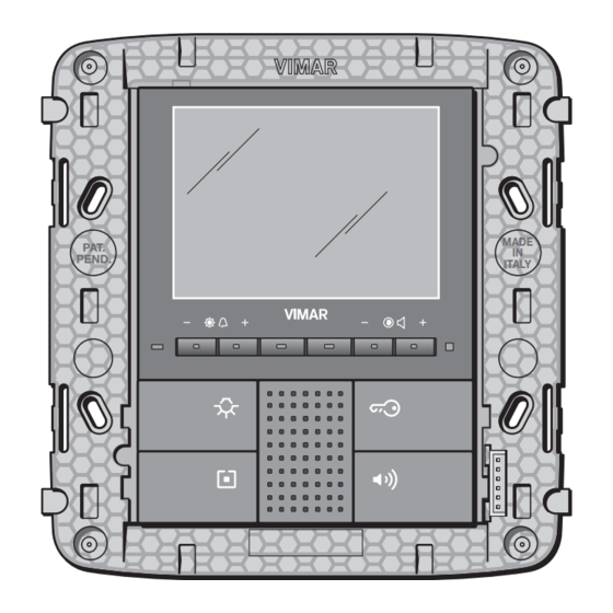
Vimar 1960 Instruction Manual (318 pages)
Control panel module for monitor 20550
Brand:
Vimar
| Category:
Control Panel
| Size: 18 MB
Table of Contents
Sections Index
2
Table of Contents
5
Introduction
6
Main Functions
7
Basic Concepts
8
Control Appliance with Three Simple Buttons and Actuator
9
Installation Topology
14
Hooking up the Control Panel Module
15
System Content
15
Bus System Installation
16
Bus Length: General Rules
17
System Setup
17
Bus Installation: Summary Table
18
Length of the BUS Line
18
Description of Terminals
19
Putting the System into Service
20
Main Configurations
21
Navigating through the Control Unit Menus
21
Initial Switch-On
22
Main Screens of the Control Panel
23
Configuration Menu
24
Creating a New Functional Group
24
A B C
25
Functional Unit Selection
25
Note on Built-In Controls
27
Rules for Creating Groups
27
Add Devices to a Functional Group
28
Modifying Device Parameters
29
Remove a Functional Unit from a Functional Group
29
Removing a Group
29
Rename a Group
29
Control Panel Reset
30
Device Identification
30
Device Reset
30
Device Parameters
31
Installing and Configuring the Touch Screens
33
Resetting the Touch Screen
34
Installation and Configuration of the By-Me Module 01965
35
Router Control
37
Communicator Interface Management
38
Phone Communicator Configuration
38
Groups Monitored from a Remote Location
39
Removing Group from Interface
39
Removing Interface
39
Managing BUS Interface with Enocean Module
40
Interface Configuration
41
Device Configuration
42
Interface Diagnostics
42
Removing the Interface
42
Changing Interface Parameters
43
Removing Devices
43
Changing the Parameters of the Device with the Enocean Module
44
Interface Number
44
Scenario Management with Toggle Button Control with Enocean Module
44
Device Identification and Strength of Reception
45
Scenario Management with Relay Actuator with Enocean Module
45
Addition of an Emergency Lamp to a Functional Group
46
Interface for Managing Emergency Lamps Via By-Me Bus
46
Setting the Lamp Parameters
46
Configuring the Interface 01847
47
Duration of Emergency
47
Removing a Lamp from a Functional Group
47
USB Interface Management 01847
47
Authentication of Interface 01847
48
Importing the Control Panel Database
48
Removing Interface 01847
48
Clock Adjustment
49
Display and Tones
49
Language Settings
49
Settings Menu
49
User Management
50
Favourite Application
51
Screen Saver
51
Air-Conditioning Control
52
Group Association
52
Zone Activation
53
Zone Deactivation
53
Zone Management
53
Zone Settings
53
Heating or Air-Conditioning Mode
54
Normal or Protected Operation
54
Temperature Differential
54
Type of System
55
Removing a Temperature Zone
57
Select Temperature Zone to be Displayed
57
Operating Modes
58
Forced Switch-Off
59
Setting the Speed of the Fan Coils
59
Programming
60
Temperature Level Settings
60
Zone Selection
60
Scenarios
61
Creating a Scenario
61
Activating a Scenario
62
Cancelling a Button Associated with the Scenario
64
Cancelling a Scenario
64
Remote Access to Scenarios
64
Renaming a Scenario
64
Load Control
65
Functionality
65
Time Slots
65
Power Management
66
Selecting the Loads to be Controlled
66
Create Functional Group
67
Displaying the Level of Power Consumed
67
Load Management
67
Setting the Power Consumption Control
67
Priority Settings
68
Load Management
69
Load Status
69
Associating an Indicator Group
70
LED Signals of the Module 01855
70
Programming Events
71
Cyclical Clock
72
Period Clock
72
Timer
72
Weekly Clock
72
Inputs
74
Outputs
75
Example Applications
76
Switch on Outside Lights in the Evening
76
Daily Watering
77
Activation of the Intrusion Detection Alarm System
79
Load Management by Time Slots
79
Shutter Automation
79
Intrusion Detection Alarm System Integration
80
Diagnostics and Maintenance
81
Diagnostics and Replacement of Devices
81
Control Panel Software Release
82
Remote Communications Management
82
Remote Control
82
Turning on SAI by SMS Via GSM Communicator 01941 with Interface 01848
83
Remote Control
83
Fitting for Connection to Interface 01998.U
84
13 Integration of the By-Me System with the Soundsystem, Digibus and Elvox Two Wire Video Door Entry
85
System Integration
85
Integration of the By-Me System with Soundsystem, Digibus and Elvox
85
14 Association between the Functions of the By-Me System and the Commands of the Two Wire Video
86
Association between the Functions of the By-Me System and the Commands
86
Door Entry System
86
External Commands Management
86
Description of Commands
87
Permission Management
88
Installation Regulations - Standard Compliance
89
Burglar Alarm
91
General Characteristics of the Alarm System
94
Connectable Devices
96
Maximum Length of Connections
97
Project Criteria
97
Sizing the System
97
Checking Power Input
99
Audible Warnings
100
Control Points
100
Zone Identification
100
Installation of the Back-Up Unit 01804 and 01807
101
Installation of the Siren for Outdoor Use
101
Installing Modular Flush-Mounting Appliances
103
Alarm System Components
104
Alarm System Control Panel
104
Automation Section
106
Passive Infrared Motion Detector with Dual Technology
106
Passive Infrared Sensor
106
Adjustable Passive Infrared Motion Detector
108
Dual Technology Presence Detector
109
Connector (Alarm System)
112
Transponder Key
114
Digital Keypad
115
Back-Up Unit for Recess-Mounting and en 50022 Rail
118
Type of Sound
120
Back-Up Unit Battery
122
Auxiliary Battery Holder Unit
123
Back-Up Unit 01807
124
Siren for Outdoor Use
126
Tamper Alarm Activation
130
Siren for Indoor Use
131
Changing Batteries
133
Power Supply 120-230 V
134
12 V Power Supply
135
Contact Interfaces
136
2-Input Contact Interface
138
Operation of Messages to Actuators
141
Settings (Programmable Via the Control Panel)
141
12 V Contact Interface
143
Relay Actuator
146
Rear View of the Relay Actuator
148
Mini Detector for Surface-Mounting
150
Dual Technology Surface-Mounting Detector
153
Transponder Reader
155
Smart Card Reader
158
Radio Interface
160
Powering up the Alarm System
164
Group/Zone Definition
165
Configuration
166
Partitions
170
S.A.I. Setup
170
Associate Partitions with SAI Control Panel
171
Associate Partitions with SPECIAL Keys
171
Associating Partitions with a Connector
171
Associating Partitions with Interfaces
171
Associating Partitions with RF Remote Controls
172
Associating Partitions with the Codes of the Digital Keypad
172
S.A.I. Key Management
172
Associate Special Key with Connectors
174
Message Management
174
Removing SAI Key and PIN Codes of the Digital Keypads
174
The “Alarm” Message
175
The “System Status” Message
175
The “Tamper Alarm” Message
175
Antiamper
176
The “Low Battery” Message
176
The “No Mains” Message
176
Events List
177
Walk Test
177
List of Alarms
178
Setting Parameters
179
Radio Frequency Interface
180
Dual Technology Recess-Mounting Detector
181
Mini IR Detector for Surface-Mounting
181
Input Contact Interface
182
Partitioning from Connector
183
Temporary Partitioning from Control Panel
183
Turning on the Alarm System
183
Using the Alarm System
183
Alarm Management
184
Delayed Detectors
184
Intrusion Alarm
184
Panic Alarm
184
Tamper Alarm
184
Summary of Indicators
185
Other Applications
188
Activation of a Bell with the Passive IR Detector
189
Activation of a Bell with the Contact Interface
190
Activation of an Electric Lock with the Connector
191
Signalling Alarm with no Audible Warning (Anti-Robbery)
192
Closing the Gas Flow Solenoid Valve in the Event of Leakage (Technical Alarm)
194
Activation of Audible Alarm Warnings (Panic Button)
196
Glossary
197
Manual for Configuring Radio-Frequency Devices with the Enocean Module Used with the By-Me Automation System
200
Bus Interface with Enocean Module
202
Technical Characteristics
202
List of Radio Frequency Devices that Can be Used
203
Pair of Buttons for Flat Control with Enocean Module
204
Operation as a Dimmer Switch
206
Operation as an On/Off Button
206
Surface-Mounting Installation
206
Customizing Buttons 20506 - 14506
207
Operation as a Roller Shade Button
207
Operation as a Scenario Button
207
Eikon - Library of Standard Symbols and Text
208
Plana - Library of Standard Symbols and Text
208
Actuator with Enocean Module 1 Relay
209
Adding Radio Rocker Push Buttons
210
Deleting All the Saved Buttons
210
Removing a Radio Rocker Push Buttons
210
Actuator Operation Without the By-Me Control Panel
211
Removing a Radio Rocker Push Button
211
Configure Radio-Frequency Devices When Used W. Burglar Alarm
214
System
214
Remote Control (01819)
219
Inserting/Changing Batteries (Remote Control)
220
Led Indicators
220
Infrared Detector (01737)
221
Configuring the Infrared Detector 01737
224
Dip-Switches
224
Detector with Magnetic Contact for Doors and Windows
226
If the N/C Contact Is Used with a Rope Detector for Roller Shutters
231
Water Detector for Protection against Flooding (01744)
232
Configuring the Water Detector 01744
233
Siren for Outdoor Use (01747)
235
Speaker System
239
General Characteristics of the Speaker System
242
Devices and Functions of the Speaker System
243
Transmitter Devices
243
Acoustic Speakers
244
Receiver Devices
244
Accessory Modules
245
Topology and Installation Rules
246
Speaker System Constraints
248
Absorption of the Devices and Sizing of the Speaker System
251
Number of Devices
252
Functionality (Speaker System)
253
Control Buttons
254
Microphone Call
254
Zone Priority
254
Alarm Clock Function
255
Audio Monitoring Function
255
Baby Control Function
255
Silencing Function
255
Speaker System Components
256
Audio Input with 2 RCA Connectors, Automatic Volume Adjustment
257
FM Radio Tuner with RDS, Coaxial Connector for External FM Aerial
259
Control Equipment with Two Toggle Switches and 8 Ohm 1 + 1 W Amplifier
261
Stereo Amplifier with 2 Outputs for Speakers 8 Ohm 10 + 10 W
263
Docking Station for Ipod/Iphone Devices, Supplied with Power Supply
265
Microphone for Selective or General Call, Voice Activation Function
267
“Push to Talk” General Call
268
“Push to Talk” Selective Call
268
Audio Monitoring
269
“Baby Control” Service
269
Interface for Transmitting By-Me Commands to IR Receiver
270
Associate Actions with the Actual Command
273
Summary of Signals of IR Interface 20584-14584
274
Branch Tap-Off for Speaker System Devices, Flush Mounting
275
Decoupler for Bus Line / Speaker System for By-Me Power Supply
275
Tap-Off for By-Me Command Devices, Flush Mounting
275
Group/Zone Management
276
Managing Audio Groups
276
Managing Audio Zones
276
Group/Zone Definition
277
Viewing the Audio Zones
278
FM Tuner Control
279
Managing the Docking Station
280
Playback Menu
280
Docking Station Database Navigation Menu
282
Details Menu of the RCA Source Associated with the IR Interface
283
Adding Devices to a Group
284
Removing Devices from a Group
284
Functional Block – FM Tuner
285
Functional Block – Microphone/Call
285
Functional Block – RCA Audio Input
285
Functional Block – Rocker Switch for Audio Control
285
Functional Block – Dock. Ipod/Iphone Station
286
Functional Block – Rocker Switch for Audio Monitoring
286
Audio Zones with Receiver Modules and By-Me Controls
287
Types of System
287
Audio Zones with Voice Call Function
288
Audio Zones with Baby Control Function
289
Audio Zones with Audio Monitoring Function
290
Audio Zones with Voice Communication Function
291
Audio Zones with Central Switch-Off
292
Glossary
293
Section Light Control
295
General Characteristics of the Light Control System
298
Devices and Functions of the Light Control System
299
Configuration on the Controller
300
Functional Unit Selection and Configuration
300
Dimmer Parameters
301
Setting/Changing the Parameters of the Dimmers
301
WHITE Dimmers
301
Ramp Operation
303
Delayed Switch-Off with Warning Function
304
Phase Cutting
305
Time for Changing Absolute Brightness
305
Flash Start
306
RGB Dimmers
307
Related Adjustments
308
Fading-Show
309
Application Examples
310
Configuring the "Actuator" Functional Unit
310
Configuring the "Left Button" Functional Unit
310
Creating Functional Groups
310
Configuring the "Right Button" Functional Unit
311
Configuring the "Power Supply 01877" Functional Unit
312
Configuring the "Middle Button" Functional Unit
313
Advertisement
Advertisement
Related Products
Vimar ELVOX 13C5
Vimar 1955
Vimar 19511
Vimar 1954
Vimar 19848.1
Vimar Arke Gas Stop Metano 19420
Vimar 19195 Series
Vimar 19195.M
Vimar 19195.B
Vimar 19513
Vimar Categories
Intercom System
Security Camera
Control Unit
Thermostat
Controller
More Vimar Manuals
Login
Sign In
OR
Sign in with Facebook
Sign in with Google
Upload manual
Upload from disk
Upload from URL