Table of Contents
Advertisement
Quick Links
Advertisement
Table of Contents

Related Manuals for Vimar Elvox SW24.W


Summary of Contents for Vimar Elvox SW24.W
- Page 1 Installer manual SW24.W Control panel for swing gates 24 Vdc...
-
Page 2: Table Of Contents
SW24.W Contents: Page Product features ................................1 System type ..................................2 Description of the terminal blocks............................2 Power supply connection..............................3 Connecting accessories ..............................3 Programming the control panel ............................6 Diagnostics ..................................21 Updating firmware .................................22 Control panel behaviour when loading settings ......................23 Control panel connection from Smartphone/Tablet .......................24... -
Page 3: Product Features
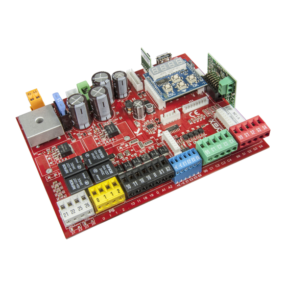
SW24.W 1 - Product features: Control panel for gear motors for 24Vdc swing gates. The control panel: - is equipped with an integrated 433 MHz rolling code or fixed code receiver, storing up to 4032 codes - is equipped with Wi-Fi connection and programming via Smartphone and Tablet using the EMC.W module and the By-gate Pro app - is equipped with a back-lit display for programming and diagnostics is used to customise all gate movement control parameters (speed and slowdown spaces, motor force, obstacle... -
Page 4: System Type
SW24.W 2 - System type: For the sizing of the cable routing, the required cross-sections of the cables are shown below. 2x1 mm² 3x0.5 mm² 2x0.5 mm² 2x0.5 mm² 4x0.5 mm² 2x2.5 mm²+ 2x2.5 mm²+ 3x0.5 mm² (encoder) 3x0.5 mm² (encoder) 3x1.5 mm²... -
Page 5: Power Supply Connection
SW24.W 4 - Power supply connection The control panel is powered at the SEC terminal with 24Vac and must be connected to the secondary terminal of a transformer for powering from the mains electricity. The transformer is supplied with the gear motor or control cabinet the control is fitted in and the secondary is pre-wired to the control panel. - Page 6 SW24.W 5.3 - Photocells and photocells in closing with photo-test on 0 1 1 2 99 S1 S2 S3 S4 8K2 (8.2 K ) 5.4 - Sensitive edge 99 S1 S2 S3 S4 8K2 (8.2 K ) N.C. 99 S1 S2 S3 S4 5.5 - Stop push button 99 S1 S2 S3 S4 99 S1 S2 S3 S4...
- Page 7 SW24.W 5.6 - Connecting two control panels in interlocking mode, output A2 = 7 (INB) The interlocking connection involves 2 gates operating according to the following method: gate 1 opens only if gate 2 is closed gate 2 opens only if gate 1 is closed When this mode is on, the safety input S4 is automatically configured without the installer selecting it as an interlock input (checking that the other gate is closed).
-
Page 8: Programming The Control Panel
SW24.W 6 - Control panel programming: 6.1 - Preliminary operations To function correctly, the control panel requires some minimum and essential settings. There are two: - Setting the motor type. In its default configuration, the control panel is not associated to any type of motor. The type of motor associated to the control panel must be set. - Page 9 SW24.W Motor parameters Type of gear motor used Warning! Default The motor type parameter is set to OFF by default. When set to OFF, the control unit does not execute any command! It is necessary to set the motor type parameter according to the type of gearmotor with which the control unit is used.
- Page 10 SW24.W Advanced travel calibration. The calibration allows the installer to choose: - Slowdown position in opening and closing - Offset for opening and closing - Pedestrian opening position Pressing Msg on Phase description button display Wait for start of calibration procedure CL 2 When button pressed: motor 2 starts closing and searches for closing stop...
- Page 11 SW24.W Gate travel parameters Power of motor 1 (%) Default Sets the value of the force given to motor 1 to push the leaf Minimum force Maximum force Power of motor 2 (%) Default Sets the value of the force given to motor 2 to push the leaf Minimum force Maximum force Default...
- Page 12 SW24.W Stop approach force reduction distance motor 1 Indicates the distance from the mechanical stop starting from which the motor 1 force is Default reduced by half (used to adjust the impact of the leaf on the mechanical stop). This happens only when the control panel works with encoder and proximity limit switch or without limit switch.
- Page 13 SW24.W Default Slowdown speed when closing motor 1 minimum speed maximum speed Default Slowdown speed when closing motor 2 minimum speed maximum speed Slowdown distance when opening motor 1 Default % of travel or total work time done at slowdown speed No slowdown Slowdown for the whole distance Slowdown distance when opening motor 2...
- Page 14 SW24.W Auxiliary output configuration Default Electric lock Output off Electrical solenoid lock Electrical drop lock Electrical magnetic lock (suction) on in closing Electrical magnetic lock (suction) on in opening and closing Electrical solenoid lock excitation time Default (adjustable at intervals of 0.1 s) 0.5 s (minimum time) 5.0 s (maximum time) Default...
- Page 15 SW24.W Default Auxiliary Radio Output Configuration Impulsive: the output is active for 1 s following the RAU command from the remote control Timed: the output is active for the time set in the RAUT parameter following the RAU command from the remote control Bistable: the output works in Step-Step ON/OFF mode Default...
- Page 16 SW24.W Input configuration C1/C2/C3/C4 command input Step-step (PP) The step-step control: - with the gate stopped and closed, opens the gate Default C1 - in opening, stops or closes the gate according to the step-step logic setting (L10) - with the gate stopped after opening, closes the gate - in closing, stops or opens the gate according to the step-step logic setting (L10) - with the gate stopped after closing, opens the gate Pedestrian (PED)
- Page 17 SW24.W S1/S2/S3/S4 safety input Default OFF Off S3/S4 Photocell closing (PHC) The closing photocell: - with the gate stopped, allows the gate to open Default - in opening does not intervene - with the gate open, does not allow it to close and when released will reset the pause time - in closing, reopens the gate immediately Photocell (PH)
- Page 18 SW24.W Control panel logic settings Default Automatic closing Automatic closing off Automatic closing on Default Pause time 1 s (minimum time) 180 s (maximum time) Default Pedestrian pause time 1 s (minimum time) 180 s (maximum time) Default State on power up Gate in closed position: The first step-step command opens the gate.
- Page 19 SW24.W Default Step by step Step-step command operates in 2 steps: open, close, open... Step-step command operates in 3 steps: open, stop, close, open... Step-step command operates in 4 steps: open, stop, close, stop, open... Default Stop from step-step Automatic closing disabled when a stop command from step-step is given Automatic closing not disabled when a stop command from step-step is given Default Stop from stop...
- Page 20 SW24.W Remote control management Saving a button as step-step oooo Waiting for code 1001 Remote control 1 saved as step-step 1055 Remote control 55 saved as step-step Saving a button as open oooo Waiting for code OPEN 2001 Remote control 1 saved as open 2055 Remote control 55 saved as open Saving a button as pedestrian...
- Page 21 SW24.W Diagnostics and reporting Alarm log reading Most recent alarm Oldest alarm Error signals Default 1 ALMA Only on display On display and maintenance output Reading of number of manoeuvres since last maintenance First 3 digits of the number of manoeuvres since last maintenance MNPC 3256 Last 4 digits of the number of manoeuvres since last maintenance...
- Page 22 SW24.W Connection module Default Connection module on CNX1 connector CNX1 No module connected Wi-Fi module EMC.W connected Restore default values and loading from memory card Loading the default values oooo Waiting press OK for 5 s to load the default values. Note: Loading the default values then requires the travel to be calibrated again, LRNT flashes on the LOAD...
-
Page 23: Diagnostics
SW24.W 7 - Diagnostics: 7.1 - Signalling Signalling indications are shown on the display for events of interest to the installer concerning normal and anoma- lous operation. They appear on the display when the associated event occurs. These indications may signal a failure if some of the system components are not working (e.g. -
Page 24: Updating Firmware
SW24.W Error alarm motor 2 not connected Motor 1 encoder error alarm Motor 2 encoder error alarm Microswitch undervoltage (check power supply and outputs) Safety test 1 failed Safety test 2 failed Safety test 3 failed Safety test 4 failed Motor 1 manoeuvre length/timeout alarm Motor 2 manoeuvre length/timeout alarm Motor 1 mosfet short alarm... -
Page 25: Control Panel Behaviour When Loading Settings
SW24.W 9 - Control panel behaviour when loading settings: On full uploading of the settings, some parameters are loaded, others maintained and others again are reset. According to the type of loading, it may be necessary to calibrate the gate travel again. To know which parameters the control panel loads, which are maintained and which are reset, refer to the table below: Action Data... -
Page 26: Control Panel Connection From Smartphone/Tablet
- an Android device with at least version 4.4 or iOS minimum version 8.0 with the By-gate Pro App installed (download- able from Google Play or App Store) - service access credentials (supplied by Vimar Spa) - for the remote connection: a Wi-Fi network connected to the internet. - Page 27 Note: The contents of this declaration correspond to what declared in the last revision of the official declaration available before printing this manual. The text herein has been re-edited for editorial purposes. A copy of the original declaration can be requested to Vimar SpA...
- Page 28 Viale Vicenza, 14 36063 Marostica VI - Italy SW24.W installer EN 09 1911 www.vimar.com...
Need help?
Do you have a question about the Elvox SW24.W and is the answer not in the manual?
Questions and answers