Table of Contents
Advertisement
Quick Links
Advertisement
Chapters
Table of Contents

Related Manuals for Vimar By-Me 21509


Summary of Contents for Vimar By-Me 21509
- Page 1 Instructions manual Control panel 21509...
- Page 4 Section automation...
-
Page 6: Table Of Contents
Table of Contents General information . . . . . . . . . . . . . . . . . . . . . . . . . . . . . . . . . . . . . . . . . . . . . . . . . . . . . . . . . . . . . . . . . . . 1. -
Page 7: General Information
General information The By-me automated system via the control unit 21509 provides integrated control of comfort, security, energy saving, HVAC and remote control in the residential and commercial sectors . This manual is arranged in a sequence of sections that provide a complete understanding of the By-me system and allow the user to take full advantage of the available features: • Chapter 1 “Main functions”: describes what can be controlled with the By-me system (see page 7);... -
Page 8: Main Functions
Main functions: 1. Main functions. The By-me system makes it possible to manage the installation using the following controls: • Ambient temperature management, dividing the installation into up to 40 areas controlled by 40 separate pro- grams; • Lighting management, with on/off control and light adjustment; • Control for roller shutters and blinds; • Function centralization and automation (up to 32 scenarios and 16 programs); • Control of the intrusion detection alarm system; • Remote control and monitoring of functions; • Power consumption and load control. • Speaker system management. COMFORT SECURITY Scenarios Wired burglar alarm system Light automation Radio burglar alarm system Shutter automation... -
Page 9: Basic Concepts
Basic concepts 2. Basic concepts. This chapter explains some fundamentally important concepts that are necessary for correctly making full use of the system . Note. Some examples refer to the device codes; for further information please refer to the product's instructions sheet. • Functional unit: part of a device that can be considered as if it were a separate device . - Page 10 Basic concepts There are no limits on the use of the functional units of a physical device . When a load is to be controlled, it is necessary to provide one control device and one actuator connected to the load . Control appliance with three simple buttons and actuator (Eikon 20545;...
- Page 11 Basic concepts • Configuration: operation that can be used to create the logic connection between various functional units (of various appliances) . • Functional group (or Group): set of functional units connected logically with each other that provide a function in the system (for example: three different buttons that control a single actuator and, as a result, the same load) .
- Page 12 Basic concepts To control the switching on of a load from different points, it is sufficient to add more functional units; it is not neces- sary to modify the wiring . Eikon 20521 Eikon 20521 Eikon 20535 Idea 16961 Idea 16961 Idea 16975 Plana 14521 Plana 14521...
- Page 13 Basic concepts • Line: any set of devices . • Scenario depth: number of scenarios to which a group can belong . Each functional group can belong to a maximum of 4 different scenarios . • Bus line: equipment used to carry the electrical or electromagnetic signals associated with the messages be- tween the system devices .
- Page 14 Basic concepts From the moment the groups are created, the control unit has no role in their operation; the devices and related functional groups are “connected” to each other and do not require any intervention by the control unit (the control unit is still needed, however, for managing editing functions, HVAC automation and automation programmes) .
-
Page 15: Installation Topology
In the case of integration between the automation system and the intrusion detection alarm system, see CONNECTION DIAGRAM with separation coupler from another automation line. 230 V~ Power supply Line 2 492.18012 0B 0409 VIMAR - Marostica - Italy 01801 POWER SUPPLY UNIT 120-230V~ 50/60Hz 440-290mA -5°C ÷... -
Page 16: Installation Of Bus Systems
-25 mA with display without backlighting (Stand By); 3.1 Bus system installation. 3.1.1 General rules and system topology. • For the connections use the twisted pair and sheathed cable VIMAR 01840 (2x0.5 mm , rated voltage to earth 400 V, suited for installation with Category I power cables) . The wire pair distributes both the power supply voltage (29 V d .c .) and the device control signals, and can be placed inside the same corrugated pipe... - Page 17 • surge protection devices to protect the installation. As regards the corrugated pipes for laying the Vimar cable 01840 of the BUS line, it is advisable to plan for a dedicated raceway; it is however possible to use those where the cables of the electric mains pass.
- Page 18 Installation topology • Essential requirements: • the distance between two power supplies must never be less than 40 m; • the load must be well distributed between the two power supplies; • the two power supplies should be placed at the ends of the one of the circuits of the system that has the largest number of devices or branches . In any case the optimal configuration has the power supplies set as far apart as possible; this has a positive effect also on the minimum voltage on the bus . 3.1.4 Length of the BUS line.
-
Page 19: Description Of Terminals
• Star configuration • Mixed configuration • We recommend using junction boxes • For the connections use the twisted pair and sheathed cable VIMAR 01840 (2x0 .5 mm , rated voltage to earth 400 V, suited for installation with Category I power cables) • Devices and distances per line • Logic capacity (number of addresses): 128... -
Page 20: Putting The System Into Service
1 . Lay out the bus cable and connecting terminals, maintaining the correct polarities (figure 3 .4 .1) . Connection terminal Vimar 01840 twisted pair 3.4.1 2 . Lay out the cable for the electrical connections of the actuators . -
Page 21: Main Configurations
Main configurations 4. Main configurations. This section describes the configuration procedures and main settings of the system . All these procedures can be carried out directly from the control unit menu, except the creation of units, which also requires an operation to be carried out on the individual devices . The more advanced system functions are discussed in later sections of this manual . -
Page 22: Initial Switch-On
Main configurations • It is possible to quickly scroll through the elements of a list with a flick. The initial scrolling speed is slow enough so as to allow reading the words; if you want to increase the speed it is necessary to subsequently flick while scrolling. Further flicks keep the scrolling active recommencing at top speed. • During navigation, arrows pointing left or right identify the possibility of making a flick or horizontal drag. • The sensitive area for flicking and dragging is equivalent to all the display of the control unit and acts on the ele- ment that has the active focus on the page . • Being a touch screen display, it is advised to use a fingertip with a light pressure that however is more than just skimming over it; performance increases if you press with a fingertip . • It is permissible to use a specific stylus for a touchscreen; whereas it is recommended not to use any sharp object such as a pen, screwdriver, electric cable, etc., to avoid damaging the display . - Page 23 Main configurations • modify device behaviour[see paragraph 4.5.4 “Modifying the device parameters - page 34]; • HVAC control [see Section 5 “HVAC Control” - page 55]; • create scenarios [see Section 6 “Scenarios” - page 66]; • load control (if load control module 01855 is available) [see Section 7 “Load control” - page 70]; • events [see chapter 8 “Programming events” - page 76]. • SAI control unit (only with the intrusion detection alarm system) [see intrusion detection alarm system section] IMPORTANT: Before proceeding with system configuration (and therefore of the vari- ous functional groups) ALWAYS reset each single device (see chap. 4.5.8 on page 35).
-
Page 24: Main Screens Of The Control Unit
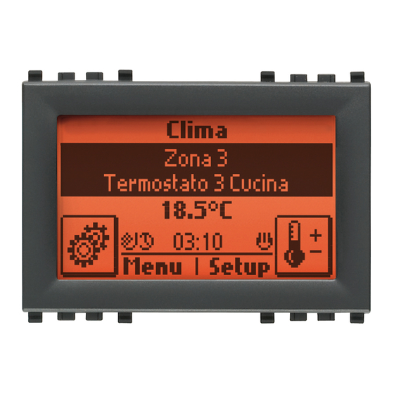
Main configurations 4.3 Control unit main screen. The control unit's main screen displays the list relating to the main menus: • HVAC; • Temperature probe; • Scenarios; • Event programmer; • Load control; • Audio; • Intrusion detection alarm system. Main Menu Climate Temperature Probe Scenarios Events Programme Audio Logout Setup The main menu is selected by touching the name of the one you want; the selection is highlighted by the black band and by the name that becomes white in colour . -
Page 25: Settings Menu
Main configurations 4.4 Settings menu. Used to adjust the control unit clock, language used, settings for the display and keypad tones, different profiles for accessing the control unit menus, the favourite applications to display on the start screen, to set the time-out to activate the screen saver and to manage the temperature probe . 4.4.1 Clock adjustment. Used to set the date and time . - Page 26 Main configurations 4.4.4 User Management. The control unit enables setting different profiles to access the menus and in this way to configure the privi- leges (that is to say the methods of use according to the user); a total of 17 users can be set (one of which is the administrator) .
- Page 27 Main configurations 4.4.4.3 Events Prog. User The only activity that the Events Prog . User can perform is to change the PIN . This operation can be carried out only by the Administrator user . Main Menu Setup Settings...
- Page 28 Main configurations - Touch all the options that you want to assign to the user; the selected ones will be marked by the symbol Options Save - Lastly, touch The control unit will display the confirmation of the operation . ...
- Page 29 Main configurations • Calibration. Selecting this option starts the measuring system calibration procedure; this procedure can be carried out only with the sensor not connected . As prescribed in the information pop-up shown on the display, make sure the probe is not connected and touch Next to start the auto-calibration mechanism .
-
Page 30: Configuration Menu
Main configurations 4.5 Configuration menu. N.B. On concluding system configuration it is possible to download the entire database of the control unit (sys- tem characteristics, etc.) onto a PC via the programming interface 01998.U. 4.5.1 Creating a new functional group. As already described in chapter 2 [Basic concepts, page 8], the functional groups (set of functional units that operate together) are basic elements of the system, so the first operation is to create them . -
Page 31: A B C
Main configurations 4.5.1.2 Functional unit selection and configuration. WARNING: For each device, how to select a functional unit is explained in the special instructions sheets that accompany the product. To configure the various functional units within a group, carry out the following: ... - Page 32 Main configurations Example 2. Functional units that can be selected by the control with 3 rocker switches with relay (Eikon 20546, Idea 16986, Plana 14546) . Functional unit selection. • To select the relay functional unit, press the configuration button (figure A); • To select the left button functional unit, press the configuration button then the left button (figure B); • To select the middle button functional unit, press the configuration button then the middle button (figure C). • To select the right button functional unit, press the configuration button then the right button (figure D). Configuration Configuration button button Left button Configuration...
- Page 33 Main configurations 4.5.1.3 Rules for creating groups. 1 . Groups must comprise only functional units that are harmonious with each other: any one group cannot contain an actuator for roller shutters and an actuator to control the lighting of a lamp . 2 .
- Page 34 Main configurations • Mounting the button: position the button in the button-holder and press lightly (figure 4.4.1.4.7). 4.4.1.4.6 4.4.1.4.7 IMPORTANT: Obviously, all the considerations made in par. 4.4.1.4 apply both for the appliances with 2 buttons and for the 3-button devices. 4.5.2 Add devices to a functional group. Used to add additional devices to an existing functional group . ...
- Page 35 Main configurations 4.5.3 Remove a functional unit from a functional group. Used to remove functional units from a functional group . Setup Configuration Groups Automation groups Select the group scrolling through the list Associated devices Select the functional unit to remove Remove device...
- Page 36 Main configurations 4.5.7 Device identification. It is possible to display information on a device that has already been configured such as its physical address and the group to which it belongs . Setup Configuration Device identification On pressing the configuration button of a device, the control unit displays the physical address and the type of device (Dimmer, RF interface, etc .) .
- Page 37 Main configurations 4.5.10 Device parameters. • Functional unit – Left push button Operation: toggle, only ON, only OFF, push-button (it sends ON on pressing the button and OFF on releasing it). LED management: off, normal, reverse, always on, normal central LED, reverse central LED, central LED always on . Default parameters: Op.
- Page 38 Main configurations • Interface for traditional controls (20515, 20518, 16955, 16958, 14515, 14518): Rocker operation: normal, reverse Button operation: toggle on up, toggle on down LED management: off, on (it is enough for one of the two inputs to be active for the LED to come on) Default parameters: Op.
- Page 39 Main configurations • Control device with three rocker switches and regulator actuator MASTER 20548, 16988, 14548 - The regulators also control inductive response electronic transformers 40-200 VA 230 V~ 50 Hz (200 VA max for 2 transformers); do not connect any more than 2 transformers . - Not suitable for controlling motors (e .g . fans, ventilators) . - If installing 2 regulators in a single box, the loads that can be controlled by each regulator must be reduced so that their total does not exceed the values indicated in the following table: 20548...
- Page 40 Main configurations If, via the touch screen, you want to control also the intrusion detection alarm system besides the automation system, the device must be connected to the line reserved for the intrusion detection alarm system (area 00-line 00) . WARNING: This does not apply to the Eikon touch screen Evo 21512 as they do not manage the intrusion detection alarm system.
- Page 41 Area 00 and Line 00 together with its power supply 01801 and router 01845 for the automation lines. 492.18012 0B 0409 VIMAR - Marostica - Italy 01801...
- Page 42 Main configurations • Router synchronization. Setup Configuration Router Router synchronization Confirm the operation by touching Yes . After configuring the devices, this operation enables the Routers controlled by the control unit, allowing the group messages to get past the line coupler . In the phase of group management it is allowed to configure devices belonging to different lines in the same group .
- Page 43 Main configurations 4.5.13 Communicator interface management. The following menus are used to configure the Internal communication interface between the BUS system and the phone communicators 01941 and 01942 . Setup Configuration Communicator interface Configuration Select the interface to configure (identified with Area no./Line no.) and touch Next .
- Page 44 Main configurations The control unit confirms the operation and returns to the list of menus for the Communicator interface . An example of the usefulness of this menu is the management of the technical alarms of a By-me system via the phone communicator: if, following a technical alarm detected in the control unit, you want the com- municator to send an alarm message (SMS or voice message), it is necessary to add the group for the contacts interface generating the technical alarm to the communicator interface .
- Page 45 Main configurations 4.5.14 USB Interface Management 01847 The menus illustrated in this paragraph allow configuring the interface 01847 for connecting the bus of the By-me system with the PC on which the EasyTool Professional program is installed . The interface 01847 is supplied with art.
- Page 46 Main configurations 4.5.15 Web Server management The menus illustrated in this paragraph are used to configure the Web Server 01945 so that the By-me system can be managed remotely via a PC or Apple mobile devices or locally by means of the multimedia video touch screen 21553 .
- Page 47 Main configurations 4.5.14 Managing BUS interface with EnOcean module The BUS with EnOcean module radio interface allows using the devices of the radiofrequency system to extend coverage in places or accesses where it is not possible to add any cables and devices via BUS . It is supplied in the following versions: 20508 : 2 Eikon modules 14508 : 2 Plana modules...
- Page 48 Main configurations RF BUS interface20508 RF command Control unit 21509 Controls Controls - 14508 20505 + buttons Main menu Climate Temperature Probe Scenarios Events Programme Logout Setup RF actuator RF actuator 01796 01796 Controls Controls with Relay actua- with relay roller shade actuator actuator...
- Page 49 Main configurations • Removing the interface. Setup Configuration Groups Automation groups Select the name of the group to which the interface belongs Associated devices Select the functional unit related to the interface to remove by scrolling through the list of units and touch Remove Device;...
- Page 50 Main configurations Touching takes you back to the previous menu that shows all the devices added on the interface, displaying the code, description and index of the associated automation group . In addition, it is possible to add the same device with the EnOcean module on more than one interface, each one in a different group, in order to increase the system's radio coverage;...
- Page 51 Main configurations • Interface number: - Progressive interface number, from 1 to 15, assigned automatically by the control unit and that cannot be modified . • Changing the parameters of the device with the EnOcean module This option allows changing the parameters related to the radio devices with the EnOcean module . The device with the EnOcean module is displayed in the menu of the Automations group with which it is as- sociated .
- Page 52 Main configurations • Scenario management with relay actuator with EnOcean module In the range of devices with the EnOcean module, the relay actuator 01796 can be used for scenario man- agement . The procedure for doing this consists in associating or removing a group in the desired scenario . Association: Activate the desired scenario to set all the devices in the desired position .
- Page 53 Main configurations 4.5.15 Interface for managing emergency lamps via By-me BUS 01846. The device, suitably installed in the emergency lighting appliance 02660 and 02660 .120, enables controlling the lamp via the control unit . For all the details on the connection of the interface to the light please see the instructions sheet supplied with art .
- Page 54 Main configurations Parameters. • Operation: Only Emergency (non-permanent SE mode) or Always On (permanent SA mode). • Emergency Duration (time for which the lamp stays on following a mains power cut): 1 or 3 hours. • Default parameters: - Operation: Only Emergency . - Emergency Duration 1 hour . • Setting the lamp parameters Setup Configuration Groups Automation groups Select the group containing the lamp and select the functional unit whose parameters are to be changed; Device Parameters lastly touch The parameters that can be modified for each functional unit depend on the characteristics of the unit...
- Page 55 Main configurations From the menu: Setup Configuration USB interface Configuration Select the interface (Area/Line) Press the USB 01847 interface configuration button for approximately two seconds; the control unit display will, for approximately two seconds, show a message confirming the configuration . At the end of this message the control unit will again display the USB Interface menu .
-
Page 56: Hvac Control
HVAC control 5. HVAC control. The By-me home automation system is used to manage climate control programs (heating and air-conditioning) using the control unit . The control unit can control up to 40 thermostats in timer-thermostat mode (Eikon 20513 - 20514, Idea 16953 -16954, Plana 14513 - 14514) permitting programmed control of up to 40 different zones. Timer-thermostat functions: • Automatic operation: 2 separate temperature programs (one for heating and one for air-conditioning on 3 tem- perature levels) for each of the 40 controlled zones. - Page 57 HVAC control 5.1.2 Creating an HVAC zone From the main menu move into the HVAC menu HVAC Zone management • New zone index (00-40); set the number that unambiguously identifies the zone and touch Next to confirm . • Group association; select, from the list of HVAC groups (created with the procedure described in par . 5.1.1), the group to associate with the zone just created.
- Page 58 HVAC control 5.2 Zone Settings This paragraph describes the procedures for setting the operating parameters of the various HVAC zones. 5.2.1 Heating or air-conditioning mode. Used to set the operating mode of the system, making it possible to select the operating mode, for each zone, for either heating (winter period) or air-conditioning (summer period) . HVAC Setup Zone settings Select the HVAC zone Operation Set the desired operation by selecting Heating or Air-conditioning and confirm with Set; after this operation touch Save .
- Page 59 HVAC control N.B. • When changing from “Normal” to “Protected” mode and vice versa, the operating mode changes automati- cally to OFF. • The reference set-point must be set with the control unit. As regards the normal or protected operation of the thermostat according to the selected mode, see the the OPERATING MODE table on the instructions sheet of art.
- Page 60 HVAC control SYSTEM WITH 2 PIPES - 1 ZONE 01851.2 OUT 1: FAN COIL SPEED V1 OUT 2: FAN COIL SPEED V2 OUT 3: FAN COIL SPEED V3 OUT 4 VALVE CONTROL OUT 1 OUT 4 20513 OUT 2 16953 NC NO C NC NO C NC NO C...
- Page 61 HVAC control SYSTEM WITH 4 PIPES - 1 ZONE 01851.2 OUT 1: FAN COIL SPEED V1 OUT 2: FAN COIL SPEED V2 OUT 3: FAN COIL SPEED V3 OUT 4 VALVE CONTROL. "HOT" 01850.2 OUT: VALVE CONTROL “COLD” SET PARAMETER “Cold Water Recirculation Pump” 230 V~ OUT 1 N.B.
- Page 62 HVAC control For the system with 4 pipes - 2 zones, the following applies: ROOM 1 AND ROOM 2. 01851.2 OUT 1: FAN COIL SPEED V1 OUT 2: FAN COIL SPEED V2 OUT 3: FAN COIL SPEED V3 OUT 4 VALVE CONTROL. "HOT" 01850.2 OUT: VALVE CONTROL “COLD” SET PARAMETER “Cold Water Recirculation Pump” WARNING.
- Page 63 Main configurations Relay actuator operating mode for a 2-pipe system. • For each HVAC zone, install art. 01851.2 using outputs 1, 2 and 3 to control the fan coil, and output 4 for the valve . • For the main circulation pump/valve, install art.01850.2 selecting mode “Hot Water Recirculation Pump”. Relay actuator operating mode for a 4-pipe system. For each HVAC zone, install art. 01851.2 using outputs 1, 2 and 3 to control the fan coil, and output 4 for the “hot” valve; then install art . 01850 .2 and use its outlet for the "cold" valve . • For the "hot" delivery main circulation pump/valve, use art.01850.2 selecting mode “Hot Water Recirculation Pump”...
-
Page 64: Operating Modes
HVAC control 5.3 Operating modes. This section describes the system operating modes that can be selected: Off, Timed Off, Antifreeze, Reduction, Timed Reduction, Manual, Timed Manual, Automatic . Note. If a Timed mode is selected, the control unit stores the previous mode and returns to this mode after the set time has elapsed. Clima Select, moving to the left (<) or to the right (>), the zone in which you want to set the mode HVAC... - Page 65 HVAC control 5.3.1 Setting the speed of the fan coils The thermostats for controlling the fan coils (Eikon 20513, Idea 16953, Plana 14513) permit adjusting the speed of the fans via a specific menu that can be shown on the display of the device or on the control unit . There are two methods of adjustment: manual and automatic.
-
Page 66: Programming
HVAC control 5.4 Programming. This section describes the procedures for setting personalized air-conditioning programs for the 40 zones. 5.4.1 Setting the automatic program The By-me system can be used to create personalized programs for automatic heating or air-conditioning control. The personalization consists of setting the value of a temperature level - that can be selected from between three different ones (T1, T2 and T3) - every 20 minutes; in the heating and air-conditioning programs the values T1, T2 and T3 are differentiable . Select the zone to be programmed. ... -
Page 67: Scenarios
Scenarios 6. Scenarios. A scenario is made up of a set of actuations that can be called at any time by means of a single command (for example to switch on the lights in a living room and at the same time lower the roller shutters and switch on the heating) . - Page 68 Scenarios The control unit asks you to set the state that the actuators will take on when the scenario is activated; using the buttons of the groups involved set the users positioning them in the desired state (ON or OFF, roller shutter raised or lowered, thermostat ON, etc.).
-
Page 69: Activating A Scenario
Scenarios 6.2 Activating a scenario. Activating a scenario enables calling up the saved state of all the actuators of the functional groups in this scenario; activation can be carried out from the control unit or from a control device . 6.2.1 Activating with the control unit. -
Page 70: Deleting A Scenario
Scenarios Scrolling vertically through the list of characters displayed and move horizontally , one by one, the desired letters to form the name; touch Save to confirm . 6.4 Cancelling a button associated with the scenario The procedure is as follows: ... -
Page 71: Load Control
Load control 7. Load control. The By-me home automation system can be used to monitor the amount of mains power being consumed, and so prevent the miniature circuit breaker from being tripped due to overload, by disconnecting the controlled loads if necessary . -
Page 72: Power Management
Load control Notes • If the Always ON state is set using a push-button, the time program is disabled until a new state is selected (using the push-button or by adjusting the device parameters at the control unit). • The time program is not inhibited if the Always ON state is set on the control unit; in this case, if necessary, the program must be disabled directly from the programming menu. - Page 73 Load control 7.2.1 Create functional group Perform the following operations: Setup Configuration Groups Load control groups Name the group and add the devices in it as described on page 29 . N.B. In the group created it is necessary to configure at least one relay actuator device and the current sensor 01855.
-
Page 74: Load Management
Load control The set indicator group will be marked by the icon . If you do not want to associate any group, select No group . The control unit will confirm the association and return to the previous screen . N.B. - Page 75 Load control Example of adding a new group and then changing the priority assigned automatically. • Existing groups: • Group A: priority P1 • Group B: priority P2 • Group C: priority P3 • New group to insert: Group D (created with priority P4) • Priority of Group D is changed from P4 to P2 • New order of priority: • Group A: priority P1 • Group D: priority P2 • Group B: priority P3 • Group C: priority P4 7.3.2 Load operation management. The load control mode can be decided for each group by selecting Automatic, AutoOff/ManOn (semi-auto-...
-
Page 76: Led Signals Of The Module 01855
Load control As illustrated on the page alongside, the initial screen displays the instantaneous power consumption and a Clima Zona 23 summary window of the loads On and Off, Forced On or Off; it is then possible to operate on them by touch- Termostato 23 Biblioteca Controllo Carichi 10.2... -
Page 77: Programming Events
Programming events 8. Programming events The By-me system enables creating advanced management functions that enable performing operations at certain times and/or when certain events occur, among which interaction with the intrusion detection alarm system. These functions can later be modified or even removed . Up to 16 different programs can be set; days of the week can be selected for each program, and the program time and duration can be set for each day of the week . - Page 78 Programming events 8.1.1.1 Inputs. Used to configure the program inputs . Input IN1 Select the type of input you want to use: Select the desired group from the list of the ones configured • Group GPR Next ...
- Page 79 Programming events Inputs Command Operation Group ON Input valid if an ON message arrives from the group Group OFF Input valid if an OFF message arrives from the group Group GPR and Group The input stays valid as long as the group is ON Group On-Off Address IDG The input stays valid as long as the group is OFF...
- Page 80 Programming events Select the only possible type of operation ( • SAI Operation Next SAI on • Group Address IDG . This option enables setting the group of a KNX system that is not the By-me sys- tem as an output (therefore enabling them to "communicate"...
- Page 81 Programming events 8.1.1.6 Timing. With this menu you can control switching the program on/off at programmed times and/or only on specific days of the week . Program Settings Timing Select the desired timing: Weekly clock : weekly daily programming of events in steps of 10 minutes . Period clock : programming, with time for beginning and end, of at most 2 daily events during the week . Cyclic clock : turning programmed events on/off according to the set time intervals.
- Page 82 Programming events • Cyclic clock Cyclically repeats an event (ON-OFF) according to the set duration and in an independent way to the day, date and time . Duration ON [h: min] Touch Set the duration of ON choosing the values of hours and minutes, then confirm with Set. Duration OFF [h: min] In a similar manner set After programming, confirm the settings made with Set .
-
Page 83: Operation
Programming events 8.2 Operation. The initial screen of the Events menu, which is accessed via the Main Menu, displays one of the created pro- grams . For example Events Programme Programme 01 Garden Sprinkler enabled Menu Setup Programma Eventi Programma 01 Annaffiatore Giardino attivato Touching... -
Page 84: Example Applications
Note. A command interface is used as an input IN1 because an external dusk/dawn sensor is used, which is not available in the Vimar catalogue. Warning! The dusk/dawn sensor must be placed in an area where it is not directly exposed to other light sources (for example car headlights), so that the outside lights are not switched off each time another light source is detected. - Page 85 Programming events 8.2.2 Daily watering. • Desired program: • water the garden in the evening; • start the program at 20:00 hours, but only if the moisture level in the soil requires it; • water two different areas of the garden at different times, for a period of 15 minutes in each area. • Weekly clock timing: a timer program is used for the required days. The timer program is then set with operations starting at 20:00 and ending at 20:40. The “start watering” command will be sent to the relay for area 1, and the “stop watering” command will be sent automatically after 15 minutes. The “start watering” command will be sent to the relay for area 2 after the first 15 minutes of watering, and the “stop watering” command will be sent automatically after 15 minutes. • Inputs: • Input from moisture sensor through a command interface (Eikon 20515, Idea 16955; Plana 14515). Create a group that contains the command interface to be used as Input IN1 of the watering program. The command interface will send an ON message if watering is required or an OFF message if the level of moisture in the soil means that watering is not required. Set the interface to “normal” or “inverted” operation, depending on the specifications of the moisture sensor (NO or NC). • On/off override input from a push-button (for example Eikon 20521, Idea 16961; Plana 14521). This device must be used only if you want to be able to manually force or inhibit watering; forcing is possible only if the time program is valid. Add the device to a group and associate it with Input IN2 of the watering program; select the operating mode as an ON/OFF rocker switch. Set the Input Logic selecting AND so that watering is done only if both inputs are ON (enable signal from the moisture sensor and from the button); or OR so that watering is done if at least one of the two inputs is ON (enable signal from the moisture sensor or from the button). With the condition of AND it is...
- Page 86 Programming events Note. For the required functionality, the moisture sensor must be placed in an area not affected by the watering, so that the water itself does not cause the sensor to react. Warning! When first installed, the attachment interface must be made to react at least once, in order to indicate the status to the control unit.
- Page 87 Programming events 8.2.3 Roller shutter automation. • Desired program: lower all the shutters after 21 .00, or when it becomes windy . Create a scenario that closes all the roller shutters; the scenario should be called up when one of the two required condition occurs .
-
Page 88: Integration Of The Passive Infrared Presence Detectors And The Contacts Interfaces
Intrusion Detection Alarm System Integration 9. Integration of the passive infrared presence detectors and the contacts interfaces. As already mentioned in the previous chapters, if the By-me system incorporates the intrusion detection alarm system (or future incorporation is planned), the control unit must be configured in Area 00 and Line 00 together with the intrusion detection alarm devices . -
Page 89: Diagnostics And Maintenance
Diagnostics and maintenance 10. Diagnostics and maintenance. 10.1 Diagnostics and replacement of devices. This sections describes the procedures for checking the device functions and how to replace them if necessary . Setup Diagnostics Device diagnostics The control unit starts a scanning procedure for monitoring the operation of all the configured devices ; if they all No device failure work the message is displayed . -
Page 90: Remote Communications Management
Diagnostics and maintenance 10.2 Remote communications management. 10.2.1 Remote control. To enable or disable remote control through the TP interface/telephone communicator 01848, follow the procedure below: Setup Diagnostics Remote Diagnostics Select Enabled or Disabled and confirm with Save . To manage the communications, refer to the instruction sheet for the TP interface/telephone communicator 01848 or the instructions manual of the communicator 01942 . -
Page 91: Installation Rules
Installation rules - Compliance with regulations 11. Installation rules. Installation should be carried out in compliance with the current regulations regarding the installation of electrical systems in the country where the products are installed . The article must be installed only in a SELV environment. 12. - Page 92 Section intrusion detection...
- Page 94 Table of Contents . General characteristics of the system ........... . Installation .
-
Page 95: General Characteristics Of The System
• polarized shunted connection for all devices, without any particular order, respecting the polarities marked on the terminals. • infrared detectors with of 17 beams on 4 planes. Vimar patent offering a better angle of detection than the conventional types with 14 beams on 3 planes. - Page 96 This solution, patented by Vimar, requires no additional mechanical devices, it eliminates the risk of false alarms and simplifies and reduces the work of installation.
- Page 97 General characteristics of the system Connectable devices The total number of connected devices, in any case, must always be less than or equal to 60 (the transponder keys must not be included in the count). The table gives the minimum and maximum number of “address- able”...
- Page 98 General characteristics of the system Project criteria Making a burglar alarm system involves the following phases: • determining the rooms to protect; • identifying the number of zones in which you want to split up the system; • determining the number of detectors and their location; • choosing the location of the control unit, connectors, any relay actuators, contact interfaces, any radio interfaces with the RF sensors to be associated After setting the system project you move on to sizing it. Sizing the system The two main rules to observe for sizing the system correctly are the following: • observe the maximum length of the connection cables between the devices (see following paragraph); • correct sizing of the power supply sources according to the size of the system you intend to make; it is funda- mental to permit an adequate operating time (24 h) in the event of a 230 V~ mains power failure .
- Page 99 General characteristics of the system A: 180 m max AUX + - Alimentatore 01801 Main menu Climate Temperature Probe Scenarios Events Programme Logout Setup B: 180 m max Maximum length per section AUX + - Alimentatore 01801 C > 40 m A: 180 m max Main menu Climate...
- Page 100 General characteristics of the system Checking power input To be able to size the system correctly, therefore checking the necessary number of back-up units, there is a system card to fill in at the time of preparing and sizing. This card, summarising the system configuration and programming, is particularly helpful when expanding the system and/or for subsequent maintenance. The card must be completed carefully following the instructions it gives and taking account of the following: The CEI 79-2 standard, for intrusion detection alarm systems, requires a minimum operating time of 24 h in the event of a power failure (the operating time is 8 h if there is a communicator) .
-
Page 101: Installation
General characteristics of the system 2. Installation Installation of the back-up unit 01804 and 01807. Make the connections to the line, but leave the battery's quick couplers disconnected . IMPORTANT! When connecting two or more back-up units it is mandatory to observe the polarity of the BUS and power supply line. - Page 102 LED must always be facing downwards). The anti-tamper protection on all the flush-mounting components is optical (Vimar patent). - an infrared LED on the back of the appliance emits a beam of IR rays, with variable power, onto the bottom of the flush-mounting box;...
-
Page 103: System Components
System components 3. System components. 3 .1 Control unit (21509) 3 .2 . Passive infrared and dual technology detectors (20485, 20486, 20487, 16935, 16937, 14485, 14487) 3 .3 Connector and transponder key (20482, 16932, 14482, 01815) 3 .4 Digital keypads (20483, 16933, 14483) 3 .5 . - Page 104 System components Alarm System No Allarm Menu Setup As already illustrated above, the icons are selected by touching the desired one . If, after a time-out of approximately 90 s, no operation is carried out, the control unit display switches off and acti- vates the screen save (if enabled) showing the time, day and date (setting what you want to be displayed is done using the “Settings”...
-
Page 105: Passive Infrared Motion Detector And With Dual Technology And Recess-Mounting
- detected the presence of a warm body with the device not configured; - detected the presence of a warm body in the WalkTest phase; The area of detection, of the volumetric type, is obtained by using a Fresnel lens divided into 17 beams on 4 planes (Vimar patent) . - Page 106 System components Installation For the infrared presence detector to work properly you need to follow these installation rules: - do not place any objects in front of the infrared sensor (plants, curtains, furniture, etc.); - do not expose it to direct light from lamps or sunlight; - do not subject it to the direct action of sources of heat;...
- Page 107 System components 5) Brightness threshold (default value 100%): the degree of brightness is read by a photoresistor and expressed with values ranging from 0% (light) to 100% (dark) in steps of 1%. This parameter is optional and can be used in case of advanced functions (e .g . in an automation group) . At bottom left there is a rear view of the infrared detector . Area of coverage of the infrared detector lens Legend: +, - : Connection to BUS...
- Page 108 System components 3.2.3 Dual technology presence detector. The dual technology sensor incorporates a microwave sensor and an infrared sensor and is able to signal people or animals passing through its area of coverage . The dual technology enables making the sensor insensitive to the most common causes of false alarms .
- Page 109 - detected the presence of a warm body with the system turned off; - detected the presence of a warm body with the device not configured; - detected the presence of a warm body in the WalkTest phase . The detection zone, of the volumetric type, is obtained by using a Fresnel lens divided into 17 beams on 4 planes (Vimar patent) and by a microwave detector with an area of coverage of 80° on the horizontal plane and 30° on the vertical plane . Side view Front view 80°...
- Page 110 System components Installation For the dual technology presence detector to work properly you need to follow these installation rules: - do not place any objects in front of the infrared sensor (plants, curtains, furniture, etc.); - do not expose it to direct light from lamps or sunlight; - do not subject it to the direct action of sources of heat;...
-
Page 111: Connector
System components 3.3 Connector The connector is the device that turns the system on and off (completely or the associated partitioned zones) after recognising the code emitted by the transponder keys . It is supplied in the following versions 20482: 2 Eikon modules 16932: 2 Idea modules 14482: 2 Plana modules Eikon Idea Plana Technical characteristics - Rated supply voltage (Vn): BUS 29 V d.c. - Protection class: IP30 - Operating temperature: -5 - +45 °C (for indoor use) - Installation: flush or surface mounting (with surface mounting box 09975…) - Page 112 System components • green LED on steady: - the system is turned on in total mode; • red/green two-colour LED blinking: - indicates that an alarm condition has occurred that is no longer in progress (alarm memory); Settings (programmable via the control unit) 1) Tamper threshold (default 0 that is disabled) the degree of sensitivity of the anti-tamper device can be set with a value between 0 (disabled) and 15 (from 1 to 15, the greater the setting, the greater the degree of sensitivity obtained) .
- Page 113 System components • Transponder key The transponder keys (01815), which need neither maintenance nor batteries, are special devices, of the size of a key ring, whose function is similar to that of conventional remote controls . Each key is equipped with a unique code that is different for each one (1000 bil- lion possible combinations) and, depending on the configuration assigned to the connectors, it is possible to turn the alarm system on and/or off or partition it.
-
Page 114: Digital Keypad
System components 3.4 Digital keypad By means of a code typed on the keypad, this device allows the system to be activated or deactivated accord- ing to the association of the partitions into which the system is subdivided . It is supplied in the following versions 20483: 2 Eikon modules 16933: 2 Idea modules 14483: 2 Plana modules... - Page 115 System components The digital keypad is used in a simple manner to switch the system completely or partially on and off as well as display the state of the system . This all happens by means of these simple operations: - enter a 5-digit PIN code and view the state of the system - select the partitions to switch on/off - confirm the operations and view the new state of the system...
- Page 116 System components Notes: - Button C is used as the delete key; pressing button C while entering the PIN or during the partition on/ off selection phase causes all the operations performed to be cancelled. - Button C is the same button also used during the configuration procedure. - A PIN code added to a keypad is also recognized by all the other keypads in the system (up to at most 30 PIN codes) .
-
Page 117: Back-Up Unit For Recess-Mounting And On Din Rail (60715 Th35)
System components 3.5 Back-up unit for recess-mounting and on DIN rail (60715 TH35) 3.5.1 Back-up unit for recess-mounting The back-up unit contains 2 lead batteries (not supplied) connected in series and kept charged by the power supply; they are used to power the system in the event of a power failure . It can be powered by the power supply 01800 or by using the AUX output of the power supply 01801 . - Page 118 System components The back-up unit has 6 output terminals: • BUS + - : power supply for the bus; • CENTR + - : terminals not used; • BATT_EXT + - : connection with the auxiliary battery holder unit 01803; • A: connection with the auxiliary battery holder unit for protection against wire cutting. By powering the back-up unit via the AUX output of the power supply 01801 it is possible to supply not only the BUS, but also the video door entry indoor station (21550-20550-14550 +01963 or 01955) and an auxiliary back-up unit .
- Page 119 System components Settings (programmable via the control unit) Anti-tamper : used to turn the protection against opening the cover of the back-up unit on/off (default NO). On/Off Beep : used to provide an audible warning whenever switching the system on/off (default OFF). System tamper sound : used to set the type of sound to be associated with the system device tamper alarm . Backup tamper sound : used to set the type of sound to be associated with the back-up unit tamper alarm Intrusion alarm : used to set the type of sound to be associated with the intrusion alarm Watchdog alarm...
-
Page 120: Technical Characteristics
System components Back-up unit battery The system is powered, in the event of the 230 V~ electric mains failing, by two lead batteries of 12 V 2 Ah (not supplied) that are housed in the device . The two batteries are connected in series to supply the line with the rated voltage of 24 V . - Page 121 System components 3.5.2 Auxiliary battery holder unit The auxiliary battery holder unit contains 2 lead batteries (not supplied) connected in series and kept charged by the main back-up power supply 01804; they can extend the duration of the power supply to the system in the event of a power failure .
- Page 122 System components 3.5.3 Back-up unit with decoupling coil, output 800 mA, power supply 29 Vd.c., installation on DIN rail (60715 TH35), it occupies 6 modules size 17.5 mm The back-up unit 01807 can be used as an alternative to the recess-mounting back-up unit 01804; it takes up 6 modules and, when used with lead batteries 12 V 2 .2 Ah, it can be installed in a consumer unit coupled with the battery holder bracket 01809 .
- Page 123 System components If the control unit tamper is enabled, an alarm will be signalled if the A-C contact is opened . If not used, the two terminals can be left disconnected, disabling tamper control from the control unit . NOTE: For the battery installation details, see the instructions sheet provided with the battery holder bracket 01809.
-
Page 124: Siren For Outdoor Use
System components Settings (programmable via the control unit) 1) Tamper: Used to activate or deactivate tamper input control (antitamper). Device reset On the control unit select Configuration Reset management Device reset and press the button on the device; the red LED will light up. Hold down the device's button until the LED goes out (approximately 8 sec .);... - Page 125 System components The siren for outdoor use has 2 terminals for connection to the bus . Characteristics • Additional protection with tropicalized steel cover; • Frequency modulated sound emission, with the possibility of associating different sounds according to the type of alarm; • Moving coil exponential horn with high acoustic efficiency; • Protection against: - wire cutting; - breakage of the lamp filament; - tampering; • Anti-sabotage device against oxygen lance (anti-flame device); • Programming the maximum duration of the alarm warning;...
- Page 126 System components Settings (programmable via the control unit) 1) Tamper management: via the control unit it is possible to set all the tamper alarms for the siren 01806: Low battery sound - audible warning if the voltage on the bus is too low ( - checking there is the horn ( Horn check Filament broken...
- Page 127 System components Device reset On the control unit select Configuration Reset management Device reset and press the siren con- figuration button; the red LED will light up. Hold down the device's button until the LED goes out (approximately 8 sec .); this operation: - deletes the groups;...
-
Page 128: Siren For Indoor Use
System components 3.7 Siren for indoor use The siren for indoor use provides audible warnings (that can be heard far away) of all alarm conditions . The device is self-powered and uses 3 rechargeable AAA NiMh batteries . It is supplied in the following versions 20495: 3 Eikon modules 16945: 3 Idea modules 14495: 3 Plana modules... - Page 129 System components Settings (programmable via the control unit) 1) Tamper threshold (default 0 that is disabled) the degree of sensitivity of the anti-tamper device can be set with a value between 0 (disabled) and 15 (from 1 to 15, the greater the setting, the greater the degree of sensitivity obtained) .
- Page 130 System components Changing batteries nr. 3 AAA HR03 NiMH 1.2 V IMPORTANT: Use solely rechargeable AAA NiMH 1.2 V batteries. Never use non-rechargeable batteries for any reason whatsoever; this is to avoid the risk of them exploding.
-
Page 131: Power Supplies
The power supply 01801 has a decoupling coil . On each line, at most 2 power supplies can be installed with the associated back-up unit . Front view and connections. 230 V~ 492.18012 0B 0409 VIMAR - Marostica - Italy Overload 01801 POWER SUPPLY UNIT... - Page 132 System components 3.8.2 12 V power supply The power supply 01830 is used in all systems containing devices (sensors, infrared barriers, etc .) that need to be powered at 12 V with a buffer battery . Front view and connections 120-230 V~ 01830 POWER SUPPLY UNIT...
-
Page 133: Contact Interfaces
System components 3.9 Contact interfaces. 3.9.1 2-input contact interface The device is used to connect the burglar alarm system with the normally closed magnetic alarm contacts, electro-mechanical rope contacts to protect blinds and roller shutters and anti-impact seismic sensors to protect windows . - Page 134 System components Rear view of the contact interface module: Legend: +, - : Connection to BUS C = common output A1 = input of the continuity wire IN1 = input configurable as: - input for contacts for roller shutters - input for magnetic contacts - input for technical alarm A2 = input of the continuity wire IN2 = input configurable as:...
- Page 135 System components Indicators • red LED for signals in the phase of configuration and alarm: - on steady during the phase of configuration and reset; - blinking due to detecting contact opening or attempted break-in of the device; The red LED keeps on blinking until the alarm that generated it is deleted or the system is turned on again; therefore it is not enough to turn off the system to cut off the alarm .
- Page 136 System components Settings (programmable via the control unit) 1) Input function 1: Input 1 can be configured for electromechanical rope contacts for roller shutters (S) or for magnetic contacts (M) or for technical alarms (T) or turned off . The default selection is: for magnetic contacts (M) . 2) Input function 2: Input 2 can be configured for electromechanical rope contacts (S) or for magnetic contacts (M) or for technical alarms (T) or turned off.
- Page 137 System components The 2-input contact interface can be configured either in a SAI program (intrusion detection alarm system) or in an Automation program. If the device has to be used in both applications (SAI and Automation) it is necessary for the interface to be configured first in the SAI and then in the Automation;...
- Page 138 System components Technical characteristics - Rated supply voltage (Vn): BUS 29 V d .c . - Protection class: IP30 - Operating temperature: -5 - +45 °C (for indoor use) - Installation: flush or surface mounting (with surface mounting box 09975…) - Type of protection: against opening and removal with optical anti-tamper device built in - Consumption: 15 mA + input of the 12V output if connected - Output: 12 V dc - 10% ( protection against short-circuiting) 10 mA max.
- Page 139 System components Magnetic contacts . Roller shutters contacts (anti-tamper short circuit) R = 15 kΩ R = optional resistor to control the short circuit on the wire . WARNING: The maximum length of the cables for connecting the contacts with the interface must not exceed 30 m.
- Page 140 System components Example Delay set to 30 s . On activating the system you have 30 s to get out; if you go back in after 30 s have passed and therefore with the system on, you have 30 s to turn off the system before it signals an alarm . If when turning on the system a magnetic contact has accidentally remained open (for example a window) in a zone that is not excluded from the activation, the intrusion detection alarm system will not be turned on; the con- tacts interface LED will become blinking red and the control unit will display the zone belonging to that contact.
-
Page 141: Relay Actuator
System components Setting the types of contact to assign to the input (programmable on the control unit only for the automa- tion program) Type of contact for the input: When the actuator activation message (ON or OFF) is sent, it is possible to select: •... - Page 142 System components Technical characteristics - Rated supply voltage (Vn): BUS 29 V d .c . - Protection class: IP30 - Operating temperature: -5 - +45 °C (for indoor use) - Installation: flush or surface mounting (with surface mounting box 09975…) - Type of protection: against opening and removal with active infrared sensor built in - Rated relay data: 1 A 30 V d.c./120 Va.c.
- Page 143 System components If a one-position stable actuator is configured in the same zone as a radio frequency device for sending technical alarms, when there is an alarm signal the relay swill switch over for a time equal to the time set in the actuator parameters . 3) External tamper (default value Yes): it is possible to turn on and off the control on the external contact (anti-tamper) directly from the control unit.
- Page 144 System components Example of technical alarm (gas detector) with connection of the relay actuator to the phone communicator . BUS FOR TECHNICAL ALARMS VIMAR BURGLAR CONVENTIONAL ALARM SYSTEM BUS SAFETY (e.g. IR detectors) SYSTEMS METANO GAS STOP (e.g. gas detectors)
-
Page 145: Mini Infrared Detector For Surface-Mounting
System components 3.11 Mini detector for surface-mounting The passive infrared presence detector is able to generate an alarm message when it detects motion of heat- emitting bodies in its area of coverage . If it is configured in a By-me system where there is both the automation and the intrusion detection alarm system, it is able, with the intrusion detection alarm system off, to control a relay in an automation group that can be used to switch on a light, activate a bell, etc . - Page 146 System components The area of detection, of the volumetric type, is obtained by using a Fresnel lens divided into 17 beams on 4 planes (Vimar patent) . Settings (programmable via the control unit) 1) Tamper threshold (default 0 that is disabled) the degree of sensitivity of the anti-tamper device can be set with a value between 0 (disabled) and 15 (from 1 to 15, the greater the setting, the greater the degree of sensitivity obtained) .
- Page 147 System components Note: The device can be configured in an SAI application or in an Automation application. If the detector is used both in an Automation application and in an SAI application, the device must always be config- ured first in the intrusion detection alarm system and then in the automation system; having done this, ...
-
Page 148: Dual Technology Detector For Surface-Mounting
System components 3.12 Dual technology surface-mounting detector The dual technology sensor integrates a microwave sensor and an infrared sensor . It is able to signal people or animals passing through its area of coverage . The dual technology enables making the sensor insensitive to the most common causes of false alarms . - Page 149 System components • red LED: - on steady during the phase of configuration and reset; - blinking in the event of an intrusion alarm or attempted tampering with the device; the LED continues to blink until the alarm that caused it is cancelled or the system is turned on again . Therefore it is not enough to turn off the system to cut off the alarm .
-
Page 150: Transponder Reader
System components The most common application of this function is to turn on the system from inside the house and, afterwards, leave by passing in front of one or more sensors without the system generating an alarm . Example Delay set to 30 s . On activating the system you have 30 s to get out;... - Page 151 System components Operation • The device reads the code of the transponder key to make the first acquisition (add keys) and in normal opera- tion it turns the system on and off sending the code to the control unit . • In the configuration phase it sends the code read to the control unit if the control unit has the “Register new key” option active and if this code is already in the device NOTE: The configuration phase is divided into two parts: • in the first part the device is configured irrespective of its positioning in the system (Configuration CA);...
- Page 152 System components Settings (programmable via the control unit) 1) Tamper threshold: (default 0 that is disabled). Value that adjusts the sensitivity of the optical anti-tamper in the transponder reader. Adjustment range from 0 (disabled) to 15 (maximum sensitivity) 2) Open if On (default No). Value that permits activating an actuator located in the zone of the transponder reader when the key is brought near to the transponder reader and the system is on.
-
Page 153: Smart Card Reader
System components 3.14 Smart card reader The smart card reader is the device that turns the system on and off (completely or partially) after recognising the code on a smart-card . Operation is identical to that of the connector with the additional possibility of interacting with the access control system . - Page 154 System components • in the second part (Configuration SAI) the device is configured in the burglar alarm system and its operat- ing mode is decided. All the "Slave" keys to use in the intrusion detection alarm system must then be added again, following the procedures illustrated in chap.7.2. Warning: The MASTER key must used as instructed in the instructions manual of the Access Control system, it does not work in the intrusion detection alarm system;...
-
Page 155: Radio Interface
System components 3.15 Radio interface The radio interface allows using the radio frequency devices to extend coverage in places or accesses where it is not possible to add any cables and devices via BUS . In addition it permits using one or more radio controls as a key to switch the system on/off The device turns the system on and off (completely or the associated partitioned zones) after receiving the code emitted by the remote controls . It is supplied in the following versions 20493: 2 Eikon modules 16943: 2 Idea modules... - Page 156 System components List of Radio frequency devices that can be used VIMAR code DESCRIPTION/COMPOSITION 01819 Two-way remote control 01737 Passive infrared intrusion detector, battery power supply (supplied) . 01738 Magnetic contact for doors and windows, battery power supply (supplied) .
- Page 157 System components Indicators • red LED on steady: - during configuration and reset; • red LED blinking: - due to system in alarm or an attempt at tampering with the device . The LED keeps on blinking until the alarm that generated it is deleted or until the system is turned on again; therefore it is not enough to turn off the system to cut off the alarm .
- Page 158 System components Control transmission and confirmation LED PANIC button OFF button ON 1 button ON 2 button Operation Pressing the 4 keys on the remote control provides 4 different functions • Button 1 OFF: Turning the system off (according to the partitions associated with the remote control code - see ...
-
Page 159: Powering Up The System
Powering up the system 4. Powering up the system • Connect the power supply to the 230 V~ mains and check that the bus cables have the following connections with Vimar cable 01840.Y (2x0.50 mm , rated voltage to earth 400 V, suited for installation with Category I power cables) or KNX certified: - red cable (+) - black cable (–) N.B. The bus is polarized so it is recommended to check its polarization before connecting all the devices. -
Page 160: Configuration
Configuration 5. Configuration The menu permits configuring the system, setting its management and performing the fault-diagnosis operations To configure a system, up to 30 different zones can be created and in each one of them associate a number of devices; in a room, for example, to manage the partitions in the best way, the perimeter detectors can be configured in one zone and the infrared ones in another. - Page 161 Group/zone definition n Add SAI device to group/zone. Setup Configuration Groups Intrusion detection alarm system groups Select the group/ zone for adding the device Press, for approximately 1 s, the configuration button of the SAI device to add to the selected group/zone; the red LED of the device will light up . Completion of this operation is confirmed by a message on the control unit and by the red LED going out on the device .
- Page 162 Configuration Code DESCRIPTION OPERATIONS TO CARRY OUT Press the OFF and ON 1 buttons together; the control 01819 Two-way remote control unit signals successful saving . Insert the battery into the detector; the red LED briefly lights up and the control unit signals successful sav- 01737 Passive infrared intrusion detector .
- Page 163 Configuration Reset Device Notes type Infrared detector (art . 20485, 16935,14485) Adjustable infrared detector (art . 20486) Dual technology recess-mounting IR detec- The setup LED blinks red/green for a few seconds after reset (art . 20487, 16937,14487) Digital keypad The setup LED blinks red/green for a few seconds after reset (art . 20483, 16933,14483) Backup unit (art . 01804 . .) Backup unit for DIN rail (60715 TH35) The setup LED blinks red/green for a few seconds after reset (art .
-
Page 164: Setup
S.A.I. Setup 6. S.A.I. Setup 6.1. Partitions This menu is fundamental as it permits creating groups of zones in the system (partitions) that can be turned on/ off and allows adding/removing zones to/from these partitions In the phase of configuring the partitions, it is important to bear in mind that each zone can be added to one and only one partition;... - Page 165 S.A.I. Setup If a zone must be able to be managed, for example, by two users with a different keypad PIN, it is wise to add this zone on its own to a partition and then associate this to both PINs If you want to change a previously configured partition, the menu to use is the following one: Main menu Intrusion detection alarm system Setup Partitions Partition management Select the partition to change • Associated zones: used to change the zones associated with the selected partition.
-
Page 166: Sai Key Management
S.A.I. Setup • Special keys This is used to associate the special keys with the corresponding partitions to be turned on or off: Select the desired key and touch the partitions to be associated; the linking will be highlighted with the ' icon . By selecting Totally On, the key turns on the entire system, while if only some partitions are marked it turns on the zones belonging to the indicated partitions. - Page 167 S.A.I. Setup The “Special” keys can be configured on a number of connectors to each one of which a dedicated partition can be associated for each special key with which it is associated . The PIN codes of the keypad 20483,16933 and 14483 are managed by the system as if they were SAI keys and therefore, once configured, they are automatically copied onto all the other keypads in the system .
-
Page 168: Message Management
S.A.I. Setup • To identify the PIN of the keypad it is necessary to enter this PIN on the keypad and press the ok button; then press the 0 button and finally confirm with ok. The control unit will display the keypad number (1, 2, etc . according to the number of keypads in the system), the name of the device and the PIN code keyed in • For the RF remote controls, simply press the ON 1 or ON 2 button;... - Page 169 S.A.I. Setup Main menu Intrusion detection alarm system Setup Message Management System status Destination Select the Zone or set the ID address of the group for which the message is intended. Touch Next Set and select Save to confirm. ...
-
Page 170: Antitamper
S.A.I. Setup 6.3.4 The Low Battery message. It is used to select the destination zone or the ID (address) of the group where the “Low Battery” message generated by the back-up unit is to be sent if the batteries discharge due to a protracted mains power shortage . It is moreover possible to set the duration (in minutes or seconds) of the signal to send to the chosen destina- tion;... -
Page 171: Walk Test
S.A.I. Setup 6.5 Walk test The Walk test is a function that allows checking the angle of detection of the volumetric sensors, contact inter- faces, etc. (configured in the zones from 1 to 30) and, more in general, checking that the system works properly without the sirens for outdoor use sounding . During the Walk test, the system behaves as if it were normally turned on but: • the sound of the sirens and indoor audible warnings is blocked;... -
Page 172: List Of Alarms
S.A.I. Setup Sistema Antintrusione Impianto 6.7 List of alarms attivato By touching the icon on the main screen of the intrusion detection alarm system, it is possible to view the Nessun Allarme Menu Setup alarms that occurred with the date and time of the alarm, the zone and the devices involved, the type of alarm and the zone, if any, to which a message associated with this type of alarm is sent. Alarm System No Allarm Menu Setup... -
Page 173: Setting Parameters
Setting parameters 7. Setting parameters By scrolling through the list of zones of the intrusion detection alarm system it is possible to select them to display the configured devices and if necessary refer to and modify the operating parameters . 7.1 Back-up unit The available parameters are: - Anti-tamper - Beep On/Off. : to have the beep at the time of turning the system on and off - Sound (can be selected to identify a system tamper alarm, cover tamper alarm, intrusion alarm, watchdog);... -
Page 174: Radio-Frequency Interface
Setting parameters 7.6 Radio frequency interface The available parameters are: - Tamper threshold: 0 = tamper switched off; 15 = maximum sensitivity - Supervision: can be turned off (Off) or on (On). - Zone ON delay from 1 to 10: 0 s = instantaneous It can be increased up to 60 s in steps of 1 s. - Zone ON delay from 11 to 20: 0 s = instantaneous It can be increased up to 60 s in steps of 1 s. -
Page 175: Dual Technology Recess-Mounting Detector
Setting parameters 7.12 Dual technology recess-mounting detector The available parameters are: - Tamper threshold: 0 = tamper switched off; 15 = maximum sensitivity; - LED enabling: Yes or No - Actuation duration: a value can be set from 1 to 250 seconds . - Brightness threshold: can be set to a value of from 0% to 100% in steps of 1% - On delay: 0 s = instantaneous Can be increased up to 62 s in steps of 12 s;... -
Page 176: Contact Interface
Setting parameters - On delay: 0 s = instantaneous It can be increased up to 62 s in steps of 1 s . - Contact threshold: from 0 to 3; - Roller shutters threshold: from 0 to 31 with or without check on short circuit . - Tamper threshold: 0 = tamper switched off;... -
Page 177: Using The System
Using the system 8. Using the system There follow the main operations to carry out for normal system use . 8.1 Turning On The system is turned on directly from the control unit or the transponder key set in contact with the surface of the connector in the position shown by the arrow, entering the code either on the keypad or with the remote control 01819 or with a smart card and reader . -
Page 178: Alarm Management
Using the system 8.5 Alarm management The possible alarms are: - intrusion alarm; - tamper alarm; - technical alarm; - panic alarm; - no mains alarm; - low battery alarm . • Intrusion alarm Intrusion alarms, generated only with the system switched on, cause a high-power sound to be emitted by the sirens for outdoor use and by the siren for indoor use in the back-up unit;... -
Page 179: Summary Of Indicators
Summary of indicators 9. Summary of indicators Problem Cause Solution During the phase of adding a There are 2 devices with the The device's red LED in the configuration device the control unit display same address . phase is on . In the control unit exit from shows The device is already the Add device menu and enter the present in the system”. - Page 180 Summary of indicators Problem Cause Solution In the test/configuration phase The twisted pair is broken Check that the output voltage of the power one or more devices fails to or has been damaged during supply is greater than 24 V . turn on . installation .
-
Page 181: Glossary
Glossary 10. Glossary Alarm Signal of a state of danger for life, property or the surrounding environment . Intrusion alarm Alarm generated by a presence, entry or attempted intrusion in a surveilled place . Tamper alarm (tampering) Alarm generated by the detection of attempted tampering with the device . This function is often indicated with the term 24 h to specify that it is always on . - Page 182 Glossary Operating states of the system System on The system is defined to be On when it is working and able to generate an intrusion alarm from one of the zones into which it has been divided . System in Configuration The system is defined to be in Configuration when, after setting this operating mode with a suitable sequence of commands, the control unit is set up for programming the devices . When the system is in the phase of Configuration, it inhibits the reception of alarm signals and therefore the sound of the sirens .
- Page 184 Section speaker system...
- Page 186 Table of Contents . General characteristics of the system ........... 186 2.
-
Page 187: General Characteristics Of The System
Presentation of the system 1. General characteristics of the system The By-me speaker system enables creating systems able to transmit up to 4 audio sources in different rooms at the same time with high signal quality (CD quality) . Thanks to the various system devices, integration with all the existing By-me controls and the range of coordinated speakers, it is possible to create mono or multi-channel systems completely integrated in the By-me system . -
Page 188: Devices And Functions
Devices and functions 2. Devices and functions The speaker system is composed of the following categories of devices: • Transmitter devices • Receiver devices • Acoustic speakers • Accessory modules 2.1 Transmitter devices The transmitter devices enable transmitting the sound coming from a sound source (e.g. HiFi system, CD player, portable MP3 players, etc..) to the system receivers. -
Page 189: Receiver Devices
Devices and functions 2.2 Receiver devices The receiver devices enable listening to the audio transmitted through one of the channels in the system . These devices are also equipped with a high quality audio amplifier that enables direct connection to the acoustic speakers . -
Page 190: Accessory Modules
Devices and functions 2.4 Accessory modules The accessory modules are those devices that, while not having any direct use by the user, are needed by the system for its operation or for creating the various possibilities of wiring/construction (see chap. 3 and 4). 01902: Decoupler for By-me power supply Decoupling module to be used at the By-me power supply output (or at the output of a line coupler). -
Page 191: Topology And Installation Rules
Topology and installation rules 3. Topologies and installation rules The new type of transfer of musical information in digital form over the same BUS where the By-me data packets transit requires some constraints for the wiring and in the construction of the system, while maintaining perfect integration with the By-me home automation system . -
Page 192: Installation Rules
Topology and installation rules In this case, the speaker system devices are configured in a different line to the other By-me devices . The second power supply and the dedicated decoupler are optional and must only be included when necessary for reasons of consumption . -
Page 193: System Constraints
System constraints Warning: By-me devices are not connected directly to the branch of the speaker system (blue branch) but through special shunts or through the devices of the speaker system (that have a special terminal). 3.2 Installation rules The following installation rules are compulsory in the sections of By-me Bus dedicated to the speaker system: 1. - Page 194 System constraints Max 300 m 20581 20582 Recess-mounted speakers 3 modules 20587 20587 Max 200 m 01901 01904 Receiver 20582 Transmitter 20587 20581 20588 20588 Recess-mounting speakers 8 modules 20587 (4+4) Recess-mounting speakers 3 modules Max 100 m 01901 Receiver 01904 01904 20582...
- Page 195 System constraints The following table illustrates the constraints of the system related to the distances between the receivers and the speakers . Distance between receiver 1+1W (art .14581, 20581) 10 m See fig . D and speakers Distance between receiver 10+10W (art .01901) and 30 m See fig .
-
Page 196: Absorption Of The Devices And Sizing Of The System
System constraints 4.2 Absorption of the devices and sizing of the system Since the system is completely integrable with By-me automation and uses the power supplies 01801, the limits of absorption to calculate for each line in the system apply generally: max . 2 By-me power supplies 01801 and therefore max . -
Page 197: Number Of Devices
System constraints Whereas, in the case in which the devices are always on opposite branches in relation to the By-me power supply, the distance must be calculated in relation to the power supply counting the devices on the branch . 01902 01801 Receivers 1+1 W... -
Page 198: Functionality
Functionality From what has been illustrated so far in relation to the topology, installation criteria and system constraints, we can summarise that: • Installation is linear (in-out) with the possibility of shunting via the special branch shunts for the speaker system 01904. • By-me devices must not be connected directly to the branch of the speaker system but only through the shunt 01903 or through the devices of the speaker system (special terminal on each device in the speaker system). -
Page 199: Control Buttons
Functionality 5.1 Control buttons The buttons perform commands that affect the whole zone with which they are associated. For instance it is possible to configure the By-me rocker switches to carry out actions such as switching the speaker system on and off, adjusting the volume, switching the audio source (channel) and skipping to the next/ previous track . Rocker switch for switching on and off (brief pressure) and adjusting the volume (long pressure) Rocker switch for switching to the audio source (top button) and skipping to the next track (bottom button) Warning: The button for passing on to the next track takes on a different meaning depending on the transmitter being controlled: in the case of the FM tuner it will pass on to the next station memory, while in the case of an... -
Page 200: Baby-Control Function
Functionality 5.3 Baby control function The microphone module enables activating the selective call when the volume perceived by the microphone exceeds a set threshold . If installed in a child’s room, the system puts the parents’ room into audio contact (Baby Control) according to the loudness of the noise . -
Page 201: System Components
System components 6. System components The By-me automation system enables controlling a speaker system using the control unit for configuring the devices and for setting the operating parameters . 6.1 Control unit. The control unit governs the operation of the entire system . It displays all the control information and is used for preliminary programming, configuration and, more generally, manage the system in its various states of operation . -
Page 202: Audio Input With 2 Rca Connectors
System components 6.2 Audio input with 2 RCA connectors, automatic adjustment of the input sensitivity, inte- grated line terminator. This device is used, via the 2 RCA connectors, to acquire, digitalize and transmit a generic analogical audio source (for instance a Hi-Fi system, CD player, portable MP3 player, etc .) over the By-me Bus . The By-me Bus is galvanically decoupled from the audio inputs . It is supplied in the following versions: 20582: 2 Eikon modules 14582: 2 Plana modules... - Page 203 System components Settings which can be configured directly from the device To adjust the sensitivity of the audio inputs on the device manually, proceed as follows: - Activate the device (status LED on) by switching on a listening zone. - Press and hold down the configuration button to increase the sensitivity . The LED blinks quickly; if the maximum value is reached, or in any case on releasing the button, the LED will return to its normal operating status .
-
Page 204: Fm Radio Tuner
System components 6.3 FM radio tuner with RDS, coaxial connector for external FM aerial, integrated line termina- tor, installation on DIN rail (60715 TH35), occupies 2 modules of 17.5 mm. The FM tuner 01900 is able to send the digital audio signal and the RDS messages received by radio over the bus. The FM tuner receives the radio stations (with the related RDS information) in the 87.50 - 108.00 MHz band and in addition allows saving up to 8 different radio stations, to then be able to call them up with commands sent over the Bus by the By-me control devices or save in the scenarios . - Page 205 System components • Sending information related to the value of the tuning memory (from 1 to 8). • Sending, if available, RDS information received from the broadcasting radio station. Settings which can be configured directly from the device • To set the type of antenna, that is to say external on connector F or internal on the bus, you need to use the jumper situated next to the antenna connector, that is: 1. Antenna on connector F: Connect together pins 3 with 5 and 4 with 6 2. Antenna on bus: Connect together pins 3 with 1 and 4 with 2 To set the FM radio input volume manually, proceed as follows: - Activate the device (status LED on) by switching on a listening zone.
-
Page 206: Control Device With Two Buttons And Amplifier
System components 6.4 Control equipment with two toggle switches and 8 ohm 1 + 1 W amplifier, incorporated line terminator, to be completed with 1 or 2 module interchangeable buttons This device enables playing the audio data received on the Bus through the speakers connected to its outputs . In addition, on the front of the device there are two rocker switches that can be configured for audio or automation functions (control of lights, roller shutters, etc .) . - Page 207 System components - With the red LED on, the control unit will configure the functional block; at the end of this operation the LED will go out . Parameters • For the functional blocks related to the two buttons it is possible to set the operating mode: - On/Off audio zone plus volume adjustment - Changing track and audio source - Sleep (timed switch-off) - Audio monitoring - ON/OFF button;...
-
Page 208: Stereo Amplifier With 2 Outputs
System components - LED with reverse operation; - LED always on for location in the dark; - central LED with normal operation; - central LED with reverse operation; - central LED always on for location in the dark . If the functional block belongs to more than one group, the command is confirmed with a change in LED status that lasts approximately 3 s . - Page 209 System components - Consumption on the bus: 20 mA - Possibility of programming the receiver zone via the control unit - Configuration button - Installation: on DIN rail (60715 TH35), size 6 modules - Red/green two-colour LED: 1) on red during configuration 2) blinking red following overheating of the amplifier 3) green to signal the state of the receiver, depending on the LED control parameter (which can be set at the time of configuration) .
-
Page 210: Docking Station For Ipod/Iphone
System components 6.6 Docking station for iPod and iPhone devices, supplied with power supply - 2 modules. (The article is composed of 2 appliances of 2 modules each, can be installed also separately) The docking station is a transmitter device that enables connecting audio sources such as iPod/iPhone (or other mp3 players, CD players, etc.) to the speaker system; the docking station acquires, digitalizes and sends over the By-me bus the signal of one of the analogue audio sources connected to it . - Page 211 System components The additional controls of the remote control mode are the following: • Select the navigation category (choose from Playlists, Artists) • Next/Previous Playlist: displaying the next or previous Playlist • Next/Previous Artist: displaying the next or previous Artist • Next/Previous Album: displaying the next or previous Album • Next/Previous Song: displaying the next or previous Song • Display information on the the song currently being played: title of the song, name of the artist and title of the album . • Select the song playback mode (Shuffle): 1 . Shuffle OFF 2 . Shuffle Songs 3 . Shuffle Albums • Select the song playback mode (Repeat): 4 . Repeat OFF 5 . Repeat 1 Song 6 .
-
Page 212: Microphone Module
System components Settings that can be configured via the control unit • LED control: Normal/Off; default value Normal If the device is active the green LED is lit, otherwise it is off; if this parameter is set with the value Off, the green LED always remains off . • Mono/Stereo: default value Stereo. - Page 213 System components - Front right-hand rocker switch that can be configured with the following functions: - If configured in an audio output group: 1) On/Off audio zone plus volume adjustment 2) Changing track and audio source 3) Sleep (timed switch-off of an audio zone) - If configured in a Call group 1) Audio Monitoring command, if configured with a remote call module 2) General and Selective Call Command if configured with the local call module (primary function of the button associated with the interchangeable buttons provided in the package) .
- Page 214 System components • “Baby Control” service. To turn this function on/off simply press and then release the bottom front left-hand button that will be followed by the LED signal . Once the function has been activated, if the volume of the voice signal picked up by the microphone exceeds the set threshold, a selective call is sent to a set of system zones; the threshold value can be set with the control unit ("Baby Control Threshold" parameter) or with Easy Tool Professional LT . The call remains active until a few seconds after the audio has returned under the threshold value to then reacti- vate automatically when later on the threshold gets exceeded .
-
Page 215: Ir Control Module
System components 6.8 Interface for transmitting By-me commands to IR receiver, together with 3 m cable. The IR interface enables controlling audio sources (stereo combo, CD/DVD players, etc) learning and emulating the commands of the original remote control of the equipment to control . Associated with an RCA transmitter (art . 20582-14582) it then allows having sound sources controlled directly by the By-me system . It is supplied in the following versions: 20584: 2 Eikon modules 14584: 2 Plana modules... - Page 216 System components Operation is ensured when, starting with the actions, the following commands thus named on the control unit are coded: Command Meaning Powering up the device, selecting the source and starting playing The device goes onto stand-by Next track/memory Skip next Select previous track/memory Skip previous Start playing...
- Page 217 System components - check that the infrared frequency of the audio device is between 30kHz and 60kHz; - if the LED is blinking red try the entire sequence again . As regards the remote control, you should save the buttons that are generally used for the ON, OFF, SKIP, PLAY, STOP, PAUSE and source selection (in the case of a multi-source device) operations and in the table below note down the reference between the name of the memory used and the corresponding remote control button . Action Remote control button Action 1...
- Page 218 System components Associate actions with the actual command. This menu is used to create the commands associating up to 4 already recorded actions . Setup Configuration Groups Audio groups Select the group where the IR interface was added ...
- Page 219 System components Command Action 1 Action 3 Action 4 Action 1 Action 7 Action 4 None Action 5 Action 1 None None Skip next Action 2 None None None Skip previous Action 3 None None None Play Action 4 None None None Stop...
-
Page 220: Line Decoupler For Bus/Speaker System For By-Me Power Supply
System components Problem Cause Solution The audio system is not con- Check that, on sending the By-me com- mand, the green LED blinks . trolled . Check the IR cable; it must be posi- tioned about 1 cm from the receiver . If necessary, before positioning the trans- mitter with the adhesive, test the send sequence varying the position . -
Page 221: Group/Zone Definition
Group/zone definition 7. Group/zone definition To configure the system it is necessary, first of all, to create the groups/zones for the speaker system; the procedure to follow is similar to the one for creating home automation system groups (Automations, Load Control, HVAC control, etc . ) . 7.1 Managing audio groups 7.1.1 Creating a group When creating groups it is necessary to follow some rules concerning the logical subdivision of the parts comprising the audio system . - Page 222 Group/zone definition n Priority An audio channel can be transmitted from one or more zones simultaneously by tuning onto a specific transmitter module . The control buttons for the various zones can perform actions involving the transmitter module (change radio station, play/stop a song); therefore the command generated by one zone could also affect the sound in another . This parameter determines the right to execute these commands, that will be performed if one zone has a priority greater than or equal to another . 5= maximum priority 0= minimum priority Select the desired value and confirm with Set. n Audio sources One zone transmits the audio source selected by the user in the specific menu.
-
Page 223: Alarm Clock Function
Group/zone definition n Max silencing volume [%] This parameter sets as a percentage the maximum value used by the receivers in this zone at the time of the request for operation in Silencing mode . 0= minimum value 100= maximum value Select the desired value and confirm with Set. n General switch-on This parameter determines if, when off, the zone must switch on when a general call arrives. On= on, Off=off Select the desired operation and confirm with Set. n Selective switch-on This parameter determines if, when off, the zone must switch on when a selective call arrives. - Page 224 Group/zone definition For each zone the display shows the number and the description, the description of the group of the transmitter Audio module associated with the channel (audio source), the description of the transmitter module and, where applica- Zona 23 Audio Biblioteca 2° Piano ble, some supplementary information (in this case the frequency for the FM tuner) . Radio FM 102.5 MHz With the...
-
Page 225: Docking Station Management
Group/zone definition n Selecting stations in memory Touching Mem activates the mode for calling up previously saved stations; with icons you can call up one of the 8 saved FM stations . The number alongside Mem is the selected station number . n Automatic search for radio stations Radio FM Radio FM... - Page 226 Group/zone definition Dockingstation 1 Dockingstation 1 Queen Queen The buttons used to manage the iPod/iPhone are the following: Best of Queen... Best of Queen... We will rock We will rock • to play the previous or next track . Dockingstation 1 Queen Dockingstation 1 • to access the Navigation Menu of the Docking Station . Best of Queen...
- Page 227 Group/zone definition The information on the song being played is continually updated: when the iPod/iPhone starts playing a track the control unit immediately displays the relevant information . Dockingstation 1 Song playback can also be changed by the events generated by By-me rocker switches configured in I-Pod audio Groups or by the rocker switches of the receivers . controllato Dockingstation 1 localmente...
-
Page 228: Details Menu Of The Rca Source Associated With The Ir Interface Ir 20586-14586
Group/zone definition to return to the list of artists . • • to return to the list of albums . • to return to the Playlist . • to return to the previous menu . 7.5.2.1 Operation Dockingstation 1 Queen The database of the iPod/iPhone can be browsed by Playlist or Artist and navigation is permissible also while playing a song . -
Page 229: Adding Devices To A Group
Group/zone definition 7.7 Adding devices to a group Used to add new devices to an existing group . For all the details see the section of the manual on the methods of creating groups . ... - Page 230 Group/zone definition n Functional unit – RCA Audio Input • L ED management: Off, Normal • A udio type: Mono, Stereo n Functional unit – FM tuner • L ED management: Off, Normal • A udio type: Mono, Stereo • S earch threshold: 0%, 100% This is the threshold beyond which a station is considered as valid during an automatic search • R DS text: Off, On • R SSI : Off,On n Functional unit –...
- Page 231 Group/zone definition n Functional unit – Rocker switch for Audio Monitoring • L ED management: Off, Normal, Reverse, Always On, Ctrl LED Normal, Ctrl LED.Reverse, Ctrl LED.On • O peration: Default = On Off This functional block refers to a rocker switch control configured automatically by the control unit to perform the function of switching audio monitoring on/off; the Operation parameter must always remain set to Audio Monitoring . The LED control parameter can also have values for the double button with the central LED (except for the rocker switch of the call microphone 20586-14586) .
-
Page 232: Types Of System
Types of system 8. Types of system This chapter, by way of example, illustrates some types of installation that can be made with the By-me speaker system . 8.1 Audio zones with receiver modules and By-me controls This example illustrates a typical installation in which one or more zones can play the audio source coming from the transmitter modules . Zone audio con moduli ricevitori e comandi By-me 20587 20585... -
Page 233: Audio Zones With Voice Call Function
Installation types 8.2 Audio zones with voice call function Zone audio con funzione di chiamata vocale 20521 20521 + 20532.20 20586 + 20532.20 Modulo di chiamata 01904 20587 20587 20582 20582 TX ingresso 01900 audio 20581 + Sintonizzatore 20581 + 20531.23 + 20531.23 + 20531.24... -
Page 234: Audio Zones With Baby Control Function
Types of system 8.3 Audio zones with Baby Control function This example illustrates a typical installation in which one or more zones can play the audio source coming from the transmitter modules . Zone audio con funzione "baby control" 20521 20521 + 20586 + 20532.20 (2) 20531.20 20587 20582 20582 01908 01900 20581 + 01901 20531.23 + 20531.24 20587 01908 20512... - Page 235 Types of system 8.4 Audio zones with audio monitoring function Zone audio con funzione ascolto ambientale 20521 + 20521 20586 20532.20 + 20532.20 01901 20587 20582 20582 01900 01907 20581 + 20531.23 + 20531.24 20587 01907 20512 20521 + 20587 (2) 20531.20 ZONA AUDIO 02 20581 +...
-
Page 236: Audio Zones With Voice Communication Function
Types of system 8.5 Audio zones with voice communication function Zone audio con funzione comunicazione vocale 20521 20521 + 20532.20 20586 + 20532.20 20587 20582 20582 01900 20588 20581 + 01901 20531.23 + 20531.24 20587 20588 20512 ZONA AUDIO 02 20587 CHIAMATA SELETTIVA 3 20581 +... -
Page 237: Audio Zones With Central Switch-Off
Types of system 8.6 Audio zones with central switch-off Zone audio con spegnimento centralizzato ZONA AUDIO 02 20521 20521 + 20532.20 + 20532.20 20521 + (2) 20531.20 20587 20582 01900 20581 + 20531.23 + 20531.24 20587 20588 20587 01901 20581 + 20531.23 + 20531.24 20587... -
Page 238: Glossary
Glossary 9. Glossary Source Device playing an audio signal . Transmission channel Frequency band associated with a transmitter used to transmit the content of the source . Transmitter (TX) Device that sends the source content over the communication bus . Receiver (RX) Device that receives the source content from the bus and transmits it in the room via acoustic speakers . - Page 239 WARNING. To read the FAQs for the By-me system, please see our website www .vimar .com under the section Support --> FAQ .
- Page 240 21509 EN 01 1206...
- Page 241 Viale Vicenza, 14 I 36063 Marostica VI Tel. +39 0424 488 600 Fax +39 0424 488 188 21509 installatore EN 01 1206 http://www.vimar.com VIMAR - Marostica - Italy...
Need help?
Do you have a question about the By-Me 21509 and is the answer not in the manual?
Questions and answers