
Related Manuals for Ventrac AP01230


Summary of Contents for Ventrac AP01230
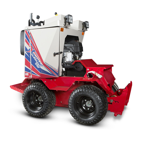
- Page 1 Operator’s Manual 2100C Serial Number 2100C-AP01001 - AP01230 VENTRAC.COM Revised 07/01/19 Original Operator’s Manual 09.10146 Rev. 03...
- Page 2 To the Owner Contact Information and Product Identification If you need to contact an authorized Ventrac dealer for information on servicing your product, always provide the product model and serial numbers. Please fill in the following information for future reference. See the picture(s) below to find the location of the identification numbers.
-
Page 3: Table Of Contents
TABLE OF CONTENTS INTRODUCTION PAGE 6 Product Description ..........................6 Why Do I Need an Operator’s Manual? ....................6 Using Your Manual ..........................7 Manual Glossary ............................7 SAFETY PAGE 8 Safety Decals ............................8 General Safety Procedures ........................11 Training Required ..........................11 Personal Protective Equipment Requirements ..................11 Operation Safety .......................... - Page 4 TABLE OF CONTENTS GENERAL OPERATION PAGE 22 Daily Inspection ............................22 Starting the Engine ..........................22 Forward and Reverse ...........................22 Turning (Left, Right, & Turn in Place) ....................23 Stopping the Power Unit ........................23 Shutting Off the Engine ........................23 Attaching ..............................24 Detaching .............................25 Operating Attachments .........................25 Front Hitch ............................25 Front Auxiliary Couplers ........................25...
- Page 5 Neutral Arm Adjustment ........................41 Neutral Switch Adjustment ........................41 Storage ..............................42 Maintenance Schedule .........................43 Maintenance Checklist .........................44 Ventrac Maintenance Log ........................45 TROUBLESHOOTING PAGE 47 Wiring Diagram Reference Key ......................47 Wiring Harness Diagram ........................48 Wiring Diagram - Optional 30.0219 4-Pin Female Socket & 30.0218 4-Pin Male Plug......50 Engine ..............................51...
-
Page 6: Introduction
The Ventrac 2100 SSV is a dedicated sidewalk snow vehicle with a 4x4 skid steer drive system. The 34 inch (86.4 cm) working width of the Ventrac 2100 allows access to narrow sidewalks and transi- tional areas, reducing the need for hand labor. -
Page 7: Using Your Manual
Manual Glossary Power Unit A Ventrac tractor or other Ventrac engine powered device that may be operated by itself or with an attachment or accessory. Attachment A piece of Ventrac equipment that requires a Power Unit for operation. -
Page 8: Safety
SAFETY Safety Decals The following safety decals must be maintained on your Ventrac 2100 power unit. Keep all safety decals legible. Remove all grease, dirt, and debris from safety decals and instructional labels. If any decals are faded, illegible, or missing, contact your dealer promptly for replacements. - Page 9 SAFETY 1. WARNING: Read operator’s manual. 2. Wear personal protective gear, such as eye protection, boots, ear protection, and warm clothing suitable for weather conditions. 3. Operators must receive training prior to operating the machine. 4. Do not operate with shields or guards removed. 5.
- Page 10 SAFETY 1. DANGER: Battery acid is caustic and can cause chemical burns. Keep by- standers a safe distance from the battery. 2. Wear eye protection, such as goggles or a face shield, when checking or servicing batteries. 3. Wear appropriate protective gear, such as rubber gloves and an apron, when 1.
-
Page 11: General Safety Procedures
SAFETY General Safety Procedures for Ventrac Power Units, Attachments, & Accessories Training Required • The owner of this machine is solely responsible for properly training the operators. • The owner/operator is solely responsible for the operation of this machine and prevention of accidents or injuries occurring to him/her- self, other people, or property. -
Page 12: Preventing Accidents
SAFETY General Safety Procedures for Ventrac Power Units, Attachments, & Accessories Operation Safety (continued) • If equipped with a high/low range feature, never shift between high and low range while on a slope. Always move the machine to level ground and engage the parking brake before shifting range. -
Page 13: Operating On Slopes
SAFETY General Safety Procedures for Ventrac Power Units, Attachments, & Accessories Operating On Slopes • Slopes can cause loss-of-control and tip-over accidents, which can result in severe injury or death. Be familiar with the emergency parking brake, along with the power unit controls and their functions. -
Page 14: Maintenance
• If the power unit, attachment, or accessory requires repairs or adjustments not instructed in the operator’s manual, the power unit, attachment, or accessory must be taken to an authorized Ventrac dealer for service. • Never perform maintenance on the power unit and/or attachment if someone is in the operator’s station. -
Page 15: Hydraulic Safety
SAFETY General Safety Procedures for Ventrac Power Units, Attachments, & Accessories Fuel Safety (continued) • Do not overfill fuel tank. Only fill to bottom of fuel neck, do not fill fuel neck full. Overfilling of fuel tank could result in engine flooding, fuel leakage from the tank, and/or damage to the emissions control system. -
Page 16: Operator Safety Interlock System
SAFETY 2100 Safety Procedures • Do not operate the Ventrac 2100 without an attachment mounted on the front. • Do not make rapid changes in speed or direction. Reduce vehicle speed on slopes and when making sharp turns to prevent loss of control. -
Page 17: Testing The Safety Interlock System
SAFETY 2100 Safety Procedures Testing the Safety Interlock System WARNING CAUTION Never operate the power unit if the safety interlock The daily inspection should be performed prior to system is malfunctioning. Do not disengage or bypass initial startup for the day. any switch. -
Page 18: Operational Controls
OPERATIONAL CONTROLS Operational Control Locations Use the following images to help identify the locations of operational controls. The letter next to each control can be referenced to the list that follows these images. Standard Operational Controls A. Cluster Gauge B. Headlight Switch C. -
Page 19: Cluster Gauge (A)
OPERATIONAL CONTROLS Cluster Gauge (A) USB Receptacle (D) The USB receptacle has two USB charging ports with a sealed cover. 1. Hour Meter 2. Low Engine Oil Pres- Drive Control Handles (E) sure Warning Light 3. PTO Indicator Light The drive control handles are used to control both 4. -
Page 20: Hydraulic Control Lever (F)
The hydraulic control lever controls the lift of the power tab when attaching unit’s front hitch and the auxiliary hydraulic circuit. or detaching Ventrac Hold is the default position of the hydraulic control attachments. lever. It holds the position of the front hitch and the Rotate the latch han- auxiliary circuit. -
Page 21: Fuel Shut-Off Valve (N)
OPERATIONAL CONTROLS Fuel Shut-off Valve (N) Brine Pump Switch (DD) The fuel shut-off valve controls the Pressing the front (1) of the brine pump flow of fuel to the power unit engine. switch turns on electrical power to the brine Turning the valve to position 1 pump. -
Page 22: General Operation
GENERAL OPERATION GENERAL OPERATION Daily Inspection 1. Turn the fuel shut-off valve to the On position. 2. Set the battery disconnect switch to the On position. 3. Pull the choke handle out to the choke on or start position. Choke may not be required if the Always set the parking brake, shut off power engine is already warm. -
Page 23: Turning (Left, Right, & Turn In Place)
GENERAL OPERATION Turning (Left, Right, & Turn in Place) Stopping the Power Unit Turning is accomplished by varying the amount of To slow or stop the power unit, move the drive stroke between the right and left drive control handles. control levers in the opposite direction that you are If the drive control handles are not moved the same traveling. -
Page 24: Attaching
GENERAL OPERATION Attaching 8. Engage the drive belt tension spring (D) on the power unit to apply tension to the attachment belt. 1. Align the power unit squarely with the attach- ment and drive forward slowly until the power unit hitch is close to the attachment frame. 2. -
Page 25: Detaching
GENERAL OPERATION Detaching Front Auxiliary Couplers 1. Park the power unit on a level surface and set CAUTION the parking brake. 2. Lower the attachment to the ground. Dirt and other debris in the hydraulic system can 3. Shut off power unit engine. cause damage to the system. -
Page 26: Weight Transfer (Optional Accessory)
GENERAL OPERATION Weight Transfer (Optional Accessory) Towing Or Pushing the Power Unit The weight transfer system transfers weight from Attention the attachment to the front wheels of the power unit. Transferring weight from the attachment to the power Avoid damage to your power unit! Before tow- unit increases traction, aids in lifting the attachment, ing, read and understand the information below. - Page 27 GENERAL OPERATION Removal of Engine Covers 7. Remove the three bolts (C) that fasten the left side cover to the airflow divider plate. If operating the power unit in temperatures above 50° F (10° C), the engine covers must be removed to prevent overheating of the engine.
- Page 28 GENERAL OPERATION Installation of Engine Covers 7. Secure the airflow divider plate to the left side cover using a 1/4 x 3/4” bolt (C), washer, and 1. Park the power unit on a level surface and flange nut and a 1/4 x 3/4” socket head cap screw engage the parking brake.
-
Page 29: Service
Attention equipment may result in corrosion of (including but not limited to) steel, aluminum, and electrical com- Ventrac recommends that service be performed ponents. Equipment that will experience repeated by a qualified technician. If you are unsure how exposure to corrosive agents should be pretreated to perform the service procedure(s), contact your with a corrosion preventative. -
Page 30: Service Access Points
SERVICE Service Access Points Lubrication Locations Throughout the service section, different access Lubrication is required at the following locations. points are referred to. The following list and images Refer to the maintenance schedule for service inter- identify shields and covers that may need to be vals and amount of grease. -
Page 31: Checking Hydraulic Oil Level
The level should be between the two notches on the dipstick. 9. If the hydraulic oil level is low, add Ventrac HydroTorq XL synthetic hydraulic oil until the proper level is reached. 10. Reinstall the dipstick into the hydraulic oil tank. -
Page 32: Changing Hydraulic Oil & Filters
Allow the power unit to sit for a minimum of five minutes. 20. Check the hydraulic oil level and add Ventrac HydroTorq XL synthetic hydraulic oil, if necessary. 21. Place the operator cushion back on the power unit. -
Page 33: Servicing Hydraulic Oil Cooler
SERVICE Servicing Hydraulic Oil Cooler 7. Check the oil level. The level should be between the Full (B) and Add (C) marks on the dipstick. 1. Brush any dirt and debris from the oil cooler screen (A) in the left door. 2. -
Page 34: Changing Engine Oil And Filter
14. Add oil to the engine. Refer to Engine Owner’s Manual for proper oil specifications and capacity. Attention: Engine Oil Recommendation For optimal engine life and performance, use Ventrac Full Synthetic Premium Full Synthetic Engine Oil. ENGINE OIL Part # 15.0037-1 SAE 10W-30 Install the oil dipstick and wipe up any oil spills. -
Page 35: Air Filter Service And Replacement
SERVICE Air Filter Service and Replacement. 8. Install the new paper filter element and tighten the band clamp. Attention 9. Place the foam element onto the paper filter ele- ment and reinstall the air filter cover. Avoid engine damage! Filling the Fuel Tank Improper service to the engine air filter can result in severe engine damage. -
Page 36: Changing The Fuel Filter
SERVICE Changing the Fuel Filter 3. Remove the key from the ignition switch and allow the engine to cool. 1. Park the power unit on a level surface and 4. Open the left and right doors. engage the parking brake. 5. -
Page 37: Removing The Battery
SERVICE Removing the Battery Cleaning the Battery and Terminals 1. Park the power unit on a level surface. 1. Park the power unit on a level surface. 2. Engage the parking brake and shut off the engine. 2. Engage the parking brake and shut off the engine. 3. -
Page 38: Jump Starting Procedure
SERVICE Jump Starting Procedure 7. Connect the negative (-) booster cable to the booster battery’s negative (-) terminal (3). DANGER 8. Connect the other end of the negative (-) booster cable to the disabled power unit’s ground stud (4). The battery produces a flammable and explosive 9. -
Page 39: Replacing The Headlights And Work Lights
SERVICE Replacing the Headlights and Work Lights Pump Drive Belt Replacement The headlights and the optional work lights are 1. Park the power unit on a level surface. equipped with LEDs and do not use a replaceable 2. Engage the parking brake and shut off the engine. bulb. -
Page 40: Pto Drive Belt Replacement
SERVICE 14. Remove the pump drive belt cover. 10. Install the new belt by sliding one end of the belt down through the main frame in front of the clutch 15. Disengage the pump belt tension spring. torque bracket. Pull the end back underneath the 16. -
Page 41: Parking Brake Adjustment
SERVICE Parking Brake Adjustment Parking Brake Switch Adjustment As the tire tread wears down, the parking brake An improperly adjusted parking brake switch can grip plates will need to be adjusted in order to hold prevent the engine from cranking. If the parking securely. -
Page 42: Operator Presence Switch Adjustment
SERVICE Operator Presence Switch Adjustment 10. After adjustment is complete, torque the platform switch bracket hardware to 100 in-lbs (11 Nm). WARNING 11. Engage the parking brake, turn the ignition key to the Off position, and remove the wheel chocks. An improperly adjusted operator presence switch Drive Control Handle Adjustment can prevent the power unit from operating or can... -
Page 43: Neutral Arm Adjustment
SERVICE Neutral Arm Adjustment Neutral Switch Adjustment 1. Park the power unit on a level surface. 1. Park the power unit on a level surface. 2. Engage the parking brake and shut off the engine. 2. Engage the parking brake and shut off the engine. 3. -
Page 44: Storage
SERVICE Storage Long Term Storage (4 Months or Longer) 1. Change the engine oil to prevent damage that can Preparing the Power Unit for Storage be caused by acidic build up in used motor oil. 1. Clean the power unit. 2. -
Page 45: Maintenance Schedule
Torque to 150 ft-lbs (203 Nm) * Ventrac recommends servicing more frequently at 1/2 the standard service interval. ** Operation in severe conditions may require more frequent service intervals. ! Consult Engine Owner's Manual for engine oil information and complete servicing information # Silicon Based Spray Lubricant % Hydraulic oil &... -
Page 46: Maintenance Checklist
Check Front Hitch Pivot Bolts. Torque to 150 ft-lbs (203 Nm) * Ventrac recommends servicing more frequently at 1/2 the standard service interval. ** Operation in severe conditions may require more frequent service intervals. ! Consult Engine Owner's Manual for engine oil information and complete servicing information # Silicon Based Spray Lubricant % Hydraulic oil &... -
Page 47: Ventrac Maintenance Log
SERVICE Ventrac Maintenance Log Model Number:___________________ Serial Number: ͞ Date: Hours: Description of Repairs/Service Initials Service - 47... - Page 48 SERVICE Ventrac Maintenance Log Date: Hours: Description of Repairs/Service Initials Service - 48...
-
Page 49: Troubleshooting
TROUBLESHOOTING Wire Reference Key Wiring Diagram Reference Key Harness Section Identifier = ^Black Wire A = 32.0178 - Harness, Wire NT Main = White Wire B = 32.0187 - Harness, Wire NT PTO = Ground C = 32.0186 - Harness, Wire NT 12V 4-Pin Front D = 32.0189 - Harness, Wire NT Brine System = Splice or Connection E = 32.0188 - Harness, Wire NT Dual Aux. -
Page 50: Wiring Harness Diagram
TROUBLESHOOTING Wiring Harness Diagram Worklight Worklight Switch Rear Front Outlet Info gauge A-085 A-073 A B C E G A-107 A-072 A-073 A-108 A-103 A-036 A-086 A-087 A-024 A-068 A-065 A-064 A-064 A-126 A-037 A-063 A-021 A-088 A-093 A-065 A-020 A-095 A-001 A-001... - Page 51 TROUBLESHOOTING Wiring Harness Diagram Battery Switch Battery A-109 Info gauge Disconnect Ground A B C E G Stud A-099 A-110 A-069 A-111 A-111 A-107 A-112 A-108 A-113 A-036 A-092 A-074 A-068 A-074 A-093 A-095 A-001 A-094 A-097 A-034 A-042 A-035 A-029 A-089 B-089...
-
Page 52: Wiring Diagram - Optional 30.0219 4-Pin Female Socket & 30.0218 4-Pin Male Plug
Wiring Diagram - Optional 30.0219 4-Pin Female Socket & 30.0218 4-Pin Male Plug Attention This connector (4-pin socket) is designed for use with Ventrac original equipment only. This connector (4-pin socket) is rated for 20 amp maximum current draw. Engine alternator and/or battery capacity determine allowable continuous draw. -
Page 53: Engine
TROUBLESHOOTING Engine Symptom: Possible Cause: Starter will not engage. Battery disconnect switch in Off position. PTO switch is engaged. Blown fuse in start circuit. Parking brake is not engaged. Parking brake switch is out of adjustment. Power unit not in neutral. Neutral switch(es) out of adjustment. -
Page 54: Electrical
TROUBLESHOOTING Electrical Symptom: Possible Cause: Battery does not charge. Loose or corroded connections. Broken or loose wire in charge system. Blown fuse in charge system. Defective battery. Defective regulator. Defective alternator. Lights do not activate. Blown fuse. Broken wire. Defective light switch. Defective light. -
Page 55: Power Unit
TROUBLESHOOTING Power Unit Symptom: Possible Cause: Power unit will not move with engine running. Hydraulic oil level is low. Parking brake is engaged. Pump control rod linkage loose or off. Hydraulic pump bypass valve is open. Pump drive belt failure. Faulty hydraulic pump or motor. -
Page 56: Specifications
SPECIFICATIONS Engine Manufacturer ........Kawasaki Model Number . -
Page 57: Fluid Capacities & Specifications
Refer to Maintenance Chart = use API Classification SJ or higher & Attention: Engine Oil Recommendation For optimal engine life and performance, use Ventrac Full Synthetic Premium Full Synthetic Engine Oil. ENGINE OIL Part # 15.0037-1 SAE 10W-30 Belt Chart... -
Page 58: Warranty
4000 Series Tractors & Attachments 2-year All Ventrac add-on kits and accessories such as: 3-point hitch, 12V front & rear power outlets, foot pedal, dual wheel kit, etc., will be covered under the above warranty periods provided they are installed by an Authorized Ventrac Dealer. - Page 59 (i) expenses relating to gasoline, oil, lubricants; (ii) loss, cost or expense relating to transportation or delivery of turf equipment from the location of owner or location where used by owner to or from any Authorized Ventrac Dealer; (iii) travel time, overtime, after hours’ time or other extraordinary repair charges or charge relating to repairs or replacements outside of normal business hours at the place of business of an Authorized Ventrac Dealer;...