
Related Manuals for Ventrac KW450


Summary of Contents for Ventrac KW450
- Page 1 ’ peratOr anual & p arts rawings eather Kw450 ODel Revised 03/11/16 Original Operator’s Manual 09.10083 Rev. 04...
- Page 2 To the Owner Contact Information and Product Identification If you need to contact an authorized Ventrac dealer for information on servicing your product, always provide the product model and serial numbers. Please fill in the following information for future reference. See the picture(s) below to find the location of the identification numbers.
- Page 3 Blank Page...
-
Page 4: Table Of Contents
Roadway Safety ...........................12 Truck Or Trailer Transport ........................12 Maintenance ............................13 Fuel Safety ............................13 Hydraulic Safety ...........................14 KW450 Safety Procedures ........................15 WEATHER CAB SETUP INSTRUCTIONS PAGE 16 Identification of Parts ..........................16 Setup Instructions for Power Unit & Weather Cab ................18 OPERATIONAL CONTROLS PAGE 28 Operational Control Locations ......................28... - Page 5 TABLE OF CONTENTS SERVICE PAGE 31 Cleaning & General Maintenance ......................31 Seatbelt Upper Mount Adjustment .......................31 Window Latch Adjustment ........................31 Door Latch Adjustment .........................31 Lower Door Window Adjustment ......................31 Wiper Blade Replacement ........................32 Interior Light Bulb Replacement ......................32 Work Light Bulb Replacement ......................32 Turn Signal Bulb Replacement ......................32 Strobe Beacon Bulb Replacement .......................32 Heater Air Filter Replacement ......................33...
-
Page 6: Introduction
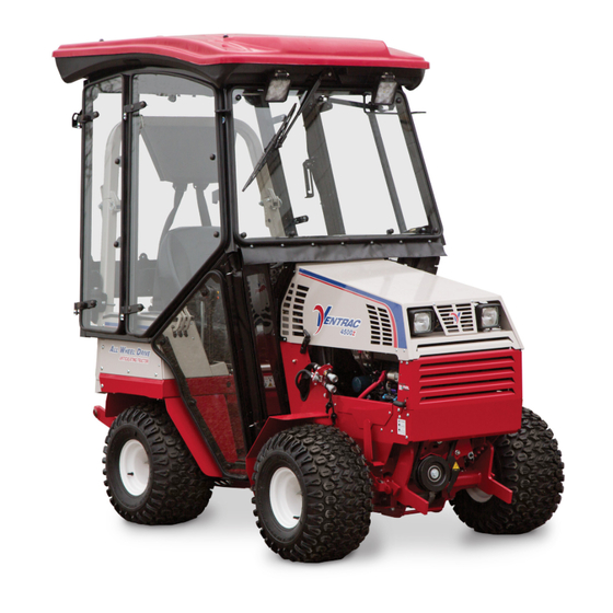
70.2009-52 Product Description The Ventrac KW450 weather cab is designed for the sole purpose of sheltering the operator from the weather while providing superior visibility. Standard features include a front windshield wiper, front and rear LED work lights, a large left-side entry door, right-side emergency exit, door and side windows that can be quickly and easily removed, and a 4-point seatbelt. -
Page 7: Using Your Manual
Manual Glossary Power Unit A Ventrac tractor or other Ventrac engine powered device that may be operated by itself or with an attachment or accessory. Attachment A piece of Ventrac equipment that requires a Power Unit for operation. -
Page 8: Safety
SAFETY Safety Decals The following safety decals must be maintained on your KW450 weather cab. Keep all safety decals legible. Remove all grease, dirt, and debris from safety decals and instructional labels. If any decals are faded, illegible, or missing, contact your dealer promptly for replacements. - Page 9 SAFETY Decal Description Part Number Quantity Warning, Pinch Point 00.0218 Warning, KW350 00.0272 Danger, Gasoline Only 00.0332 Danger, Diesel Only 00.0333 Safety - 9...
-
Page 10: General Safety Procedures
SAFETY General Safety Procedures for Ventrac Power Units, Attachments, & Accessories Training Required • The owner of this machine is solely responsible for properly training the operators. • The owner/operator is solely responsible for the operation of this machine and prevention of accidents or injuries occurring to him/her- self, other people, or property. -
Page 11: Preventing Accidents
SAFETY General Safety Procedures for Ventrac Power Units, Attachments, & Accessories Operation Safety (continued) • If equipped with a high/low range feature, never shift between high and low range while on a slope. Always move the machine to level ground and engage the parking brake before shifting range. -
Page 12: Operating On Slopes
SAFETY General Safety Procedures for Ventrac Power Units, Attachments, & Accessories Operating On Slopes • Slopes can cause loss-of-control and tip-over accidents, which can result in severe injury or death. Be familiar with the emergency parking brake, along with the power unit controls and their functions. -
Page 13: Maintenance
• If the power unit, attachment, or accessory requires repairs or adjustments not instructed in the operator’s manual, the power unit, attachment, or accessory must be taken to an authorized Ventrac dealer for service. • Never perform maintenance on the power unit and/or attachment if someone is sitting in the operator’s seat. -
Page 14: Hydraulic Safety
SAFETY General Safety Procedures for Ventrac Power Units, Attachments, & Accessories Fuel Safety (continued) • Do not overfill fuel tank. Only fill to bottom of fuel neck, do not fill fuel neck full. Overfilling of fuel tank could result in engine flooding, fuel leakage from the tank, and/or damage to the emissions control system. -
Page 15: Kw450 Safety Procedures
Do not operate power unit and KW450 weather cab without the headrest cushion in place. • The KW450 weather cab is equipped with an emergency exit (the right side front window). Learn to use the emergency exit prior to operating the power unit and KW450 weather cab. Refer to General Operation sec- tion of this manual for instructions on using the emergency exit. -
Page 16: Weather Cab Setup Instructions
WEATHER CAB SETUP INSTRUCTIONS Identification of Parts Setup - 16... - Page 17 Ref. Name Qty. Ref. Name Qty. Sling, 4 Point Assy Harness, Wire Tractor To KW450 Cushion, Headrest Clamp, Wire Mt Adh. 1/2 Gray Mount, Seatbelt Upper (w/seatbelt) Washer, .531 X 1.75 3/16 Thick Cover, Pump W/Flanges Plate, Drill Template KW450...
-
Page 18: Setup Instructions For Power Unit & Weather Cab
Disconnect the left and right wire harnesses from the harness splitter. Remove the connectors from Use only the KW450 lift sling attached at all four lift points to lift the cab. the left and right harness ends with a weather pack terminal removal tool. - Page 19 WEATHER CAB SETUP INSTRUCTIONS 7. If your power unit does not have lower mounting 13. Install the mount support bracket (D) under the holes, install the included template onto the right right foot platform. Fasten loosely with 2) 1/4” x side of the lower rear frame.
- Page 20 WEATHER CAB SETUP INSTRUCTIONS 16. Remove the right and left foot pegs from the 21. Install a 5” piece of 1/2” wide velcro loop (H) to power unit front frame. Reinstall bolts and tighten. the left dash panel above the front fuse panel. 17.
- Page 21 WEATHER CAB SETUP INSTRUCTIONS 27. Place the wire harness in the power unit’s seat 31. Tilt the seat forward as far as possible and box area. Connect the ring terminal to the ground secure in place. stud (N). Route the wire with the terminal along 32.
- Page 22 WEATHER CAB SETUP INSTRUCTIONS 38. Remove the existing seat belt from the power unit. 41. Remove the 2) 1/4 x 3/4” button head bolts from Install the seatbelt upper mount to the back edge the inside of the left fender and discard the flange of the roll bar as shown below.
- Page 23 WEATHER CAB SETUP INSTRUCTIONS 44. Install the rear cab dow open slightly and lower the handle so the mounts latch pin exits through the release slot. Parallel with onto the top face of the roll bar seat box panel. using 2) U-bolts and 4) 3/8”...
- Page 24 1/2” bolt on the bottom side of each cab mount isolator and fasten with a 1/2” locking flange nut. Use only the KW450 lift sling attached at all four 57. Tighten the hardware for the front cab supports lift points to lift the cab.
- Page 25 WEATHER CAB SETUP INSTRUCTIONS 60. Align the gas 63. Install the lower door door shock end window and the with the mount- lower door window ing stud on the bracket (DD). cab frame and Remove the nuts press until from the 4) step shock end bolts installed in the snaps over the...
- Page 26 WEATHER CAB SETUP INSTRUCTIONS 67. Lay out the 71. Remove the blank cover from the back of the Left Right canvas bellows seat box frame, route the wire harness through with the Velcro the access cutout, and connect to the wire har- on the triangular ness installed earlier.
- Page 27 WEATHER CAB SETUP INSTRUCTIONS CAUTION Do not exceed 30 amp draw to weather cab and additional accessories. Install the 30 amp circuit breaker into slot 2 of the rear fuse panel. 79. If the power unit is equipped with a gasoline engine, install the gasoline safety decal onto the cab frame next to the fuel tank cover.
-
Page 28: Operational Controls
Operational Control Locations The images above match with the following refer- ence letters to help identify the location of operational controls for the KW450 Weather Cab. A - Outer Door Handle & Lock B - Inner Door Handle C - Emergency Exit/Window Latch Handle... -
Page 29: Outer Door Handle & Lock (A)
OPERATIONAL CONTROLS Outer Door Handle & Lock (A) Rear Work Light Switch (I) Push the button on the outer door handle to unlatch Pressing the top portion of the rear work light switch the door. The outer door handle can be locked with turns the rear work light on. -
Page 30: General Operation
GENERAL OPERATION GENERAL OPERATION Daily Inspection Fasten the upper buckle of the 4-point seatbelt and adjust the left and right shoulder belts. The shoulder belts must be loose enough to allow the operator to reach all dash controls, but should be snug at the point that the operator can reach the dash controls. -
Page 31: Service
For best results, and to maintain the finish of the KW450, clean or wash the weather cab to remove dirt, gravel, and salt deposits. Remove any ice or snow accumulations from the roof, windows, and accessories. -
Page 32: Wiper Blade Replacement
SERVICE Wiper Blade Replacement Turn Signal Bulb Replacement The wiper blade should be replaced 1. Remove the 3) on a yearly basis, or sooner if the screws (A) from the blade does not clean the windshield turn signal lens and effectively. -
Page 33: Heater Air Filter Replacement
SERVICE Heater Air Filter Replacement 4. Reinstall the fuse block cover and thumb screws. The 2) heater air intake filters should be replaced on a yearly basis, or sooner if operating in dusty conditions. 1. Remove the 2) thumb screws (A) holding each filter cover (B) onto the cab. -
Page 34: Storage
14. Attach lift sling to a hoist and position above the weather cab. Use only the KW450 lift sling attached at all four Clip the 4) lift sling hooks to the lift points at each lift points to lift the cab. - Page 35 SERVICE 15. Remove the rear cab mounts from the power unit roll bar and store with the cab. 16. Loosen the 1/2” bolts that fasten the front cab supports to the front cab mounts, but do not remove. Remove the front cab mounts from the power unit foot platform and store with the cab.
-
Page 36: Specifications
SPECIFICATIONS SPECIFICATIONS Dimensions Overall Height ........51 in. (129.5 cm) Overall Length . -
Page 37: Parts
Blinker Green Lead DIMENSION IN INCHES Rear Worklight Black Lead White Lead .XX = ± 0.015 .XXX = ± 0.005 Use only original Ventrac Illustrated Parts - 37 .XXXX = ± 0.0005 replacement parts. Hole Locations/Ge NOTE: THIS DRAW MANUFACTU... -
Page 38: Cab Frame & Mount
PARTS ILLUSTRATED DRAWING Cab Frame & Mount Use only original Ventrac Illustrated Parts - 38 replacement parts. - Page 39 22 ..05.0036 ....GROMMET, 1 1/2ID,2 1/8OD,9/16T ..........1 Use only original Ventrac Illustrated Parts - 39 replacement parts.
-
Page 40: Cab Headliner & Roof Mount
PARTS ILLUSTRATED DRAWING Cab Headliner & Roof Mount Use only original Ventrac Illustrated Parts - 40 replacement parts. - Page 41 14 ..90.0420-2 ....BOLT, 1/4-20 X 2” TAP ZP ........... 4 *Sold by the foot. Specify length when ordering. Use only original Ventrac Illustrated Parts - 41...
-
Page 42: Headliner Assembly
PARTS ILLUSTRATED DRAWING Headliner Assembly 16 16 Use only original Ventrac Illustrated Parts - 42 replacement parts. - Page 43 28 ..07.010012 ....UPHOLSTERY, HEADLINER GRAY ......... . . 1 *Sold by the foot. Specify length when ordering. Use only original Ventrac Illustrated Parts - 43...
-
Page 44: Front & Rear Work Lights
PARTS ILLUSTRATED DRAWING Front & Rear Work Lights Use only original Ventrac Illustrated Parts - 44 replacement parts. - Page 45 22 ..99.M0025 ....NUT, M8 X 1.25 ZP ............1 Use only original Ventrac Illustrated Parts - 45 replacement parts.
-
Page 46: Canvas Bellows & Column Covers
PARTS ILLUSTRATED DRAWING Canvas Bellows & Column Covers Use only original Ventrac Illustrated Parts - 46 replacement parts. - Page 47 19 ..60.1180 ....COVER, PUMP W/FLANGES ..........1 *Sold by the foot. Specify length when ordering. Use only original Ventrac Illustrated Parts - 47...
-
Page 48: Front Windshield & Windshield Wiper
PARTS ILLUSTRATED DRAWING Front Windshield & Windshield Wiper Use only original Ventrac Illustrated Parts - 48 replacement parts. - Page 49 21 ..44.0276 ....CANVAS,WINDSHIELD BOTTOM ..........1 *Sold by the foot. Specify length when ordering. Use only original Ventrac Illustrated Parts - 49...
-
Page 50: Upper Door Frame & Latch
PARTS ILLUSTRATED DRAWING Upper Door Frame & Latch Use only original Ventrac Illustrated Parts - 50 replacement parts. - Page 51 36 ..64.1489 ....BRACKET, DOOR GLASS MOUNT ..........1 *Sold by the foot. Specify length when ordering. Use only original Ventrac Illustrated Parts - 51...
-
Page 52: Lower Door
PARTS ILLUSTRATED DRAWING Lower Door Use only original Ventrac Illustrated Parts - 52 replacement parts. - Page 53 15 ..64.1472 ....SUPPORT, DOOR WINDOW LOWER ......... . 1 *Sold by the foot. Specify length when ordering. Use only original Ventrac Illustrated Parts - 53...
-
Page 54: Left Rear Window
PARTS ILLUSTRATED DRAWING Left Rear Window Use only original Ventrac Illustrated Parts - 54 replacement parts. - Page 55 19 ..99.A05 .....LOCKNUT, STOVER 5/16-18 USS ..........1 *Sold by the foot. Specify length when ordering. Use only original Ventrac Illustrated Parts - 55...
-
Page 56: Rear Window
PARTS ILLUSTRATED DRAWING Rear Window Use only original Ventrac Illustrated Parts - 56 replacement parts. - Page 57 25 ..06.0072* ....TRIM, SEAL DOUBLE BULB 3/16” X 140” ........1 *Sold by the foot. Specify length when ordering. Use only original Ventrac Illustrated Parts - 57...
-
Page 58: Right Rear Window
PARTS ILLUSTRATED DRAWING Right Rear Window Use only original Ventrac Illustrated Parts - 58 replacement parts. - Page 59 19 ..06.0072* ....TRIM, SEAL DOUBLE BULB 3/16” X 110” ........1 *Sold by the foot. Specify length when ordering. Use only original Ventrac Illustrated Parts - 59...
-
Page 60: Right Front Window/Emergency Exit
PARTS ILLUSTRATED DRAWING Right Front Window/Emergency Exit Use only original Ventrac Illustrated Parts - 60 replacement parts. - Page 61 19 ..07.0100019 ....PIN, WINDOW ARM ............1 *Sold by the foot. Specify length when ordering. Use only original Ventrac Illustrated Parts - 61...
-
Page 62: Lower Right Window
PARTS ILLUSTRATED DRAWING Lower Right Window Use only original Ventrac Illustrated Parts - 62 replacement parts. - Page 63 10 ..06.0064* ....WEATHERSTRIP, 1”X1”X24”L D-SHAPE ........1 *Sold by the foot. Specify length when ordering. Use only original Ventrac Illustrated Parts - 63...
-
Page 64: Four Point Seatbelt
PARTS ILLUSTRATED DRAWING Four Point Seatbelt Use only original Ventrac Illustrated Parts - 64 replacement parts. - Page 65 15 ..47.0280 ....SEAT BELT, 4 POINT ............1 *Sold by the foot. Specify length when ordering. Use only original Ventrac Illustrated Parts - 65...
-
Page 66: Fuel Tank Cover, Seals, Wire Harness
PARTS ILLUSTRATED DRAWING Fuel Tank Cover, Seals, Wire Harness Use only original Ventrac Illustrated Parts - 66 replacement parts. - Page 67 7 ..32.0129 ....HARNESS, WIRE TRACTOR TO KW450 ..
-
Page 68: 70.2005-2 Directional Signal/Flasher Kit
PARTS ILLUSTRATED DRAWING 70.2005-2 Directional Signal/Flasher Kit 07.0100903 Use only original Ventrac Illustrated Parts - 68 replacement parts. - Page 69 22 ..99.M0026 ....NUT, M12 X 1.25 ............1 Use only original Ventrac Illustrated Parts - 69 replacement parts.
-
Page 70: 70.2006-3 Strobe Beacon Kit
PARTS ILLUSTRATED DRAWING 70.2006-3 Strobe Beacon Kit 33.0049 Use only original Ventrac Illustrated Parts - 70 replacement parts. - Page 71 33 ..33.0049-1 ....RING, CLAMP ............1 Use only original Ventrac Illustrated Parts - 71 replacement parts.
-
Page 72: 70.2006-4 Mirror Kit
PARTS ILLUSTRATED DRAWING 70.2006-4 Mirror Kit Use only original Ventrac Illustrated Parts - 72 replacement parts. - Page 73 12 ..94.05 ..... .WASHER, FLAT 5/16 USS ........... 4 Use only original Ventrac Illustrated Parts - 73 replacement parts.
-
Page 74: 70.2006-6 Defrost Fan Kit
PARTS ILLUSTRATED DRAWING 70.2006-6 Defrost Fan Kit Use only original Ventrac Illustrated Parts - 74 replacement parts. - Page 75 3 ..37.0051 ....FAN, DEFROSTER ............1 Use only original Ventrac Illustrated Parts - 75 replacement parts.
-
Page 76: 70.8106 Console Fan/Heater Kit
PARTS ILLUSTRATED DRAWING 70.8106 Console Fan/Heater Kit Use only original Ventrac Illustrated Parts - 76 replacement parts. - Page 77 19 ..07.0102058 ....KNOB, 1/4-20 X 1” 4-LOBE ..........4 *Sold by the foot. Specify length when ordering. Use only original Ventrac Illustrated Parts - 77...
-
Page 78: 70.8136 Kubota Heater Install Kit For 4500Y & 4500Z
PARTS ILLUSTRATED DRAWING 70.8136 Kubota Heater Install Kit For 4500Y & 4500Z Use only original Ventrac Illustrated Parts - 78 replacement parts. - Page 79 13 ..25.2408-06^ ....FITTING, PLUG -6 MJIC ........... . 2 ^These fittings are used to plug the hoses when the cab is removed from the power unit. Use only original Ventrac Illustrated Parts - 79...
-
Page 80: 70.8137 Kawasaki Heater Install Kit For 4500P
PARTS ILLUSTRATED DRAWING 70.8137 Kawasaki Heater Install Kit For 4500P Use only original Ventrac Illustrated Parts - 80 replacement parts. - Page 81 13 ..25.2408-06^ ....FITTING, PLUG -6 MJIC ........... . 2 ^These fittings are used to plug the hoses when the cab is removed from the power unit. Use only original Ventrac Illustrated Parts - 81...
-
Page 82: Warranty
Ventrac equipment. Proof of purchase may be required by the dealer to substantiate any warranty claim. - Page 83 (i) damage or defects due to or arising out of repair of Ventrac turf equipment by person or persons other than an authorized Ventrac service dealer or the installation of parts other than genuine Ventrac parts or Ventrac recommended parts.
Need help?
Do you have a question about the KW450 and is the answer not in the manual?
Questions and answers