
Summary of Contents for AerPOS AP-3615
- Page 1 Version 0.5 AP-3615 15” Bezel Free Performance POS Terminal...
- Page 2 Copyright Notice This document is copyrighted, 2012. All rights are reserved. Firich Enterprises Co., Ltd reserves © the right to make improvements of the product described in this manual at any time without notice. No part of this manual may be reproduced, copied, translated, or transmitted in any form or by any means without the prior written permission from Firich Enterprises Co., Ltd.
- Page 3 Safety and Warranty 1. Read these safety instructions carefully. 2. Keep this user's manual for later reference. 3. Disconnect this equipment from any AC outlet before cleaning. Do not use liquid or spray detergents for cleaning. Use a damp cloth. 4.
-
Page 4: Table Of Contents
Introduction AerPOS ( AP-3615 ) Introduction..................1 A Quick Tour for AP-3615....................2 AP-3615 Dimension ...................... 3 Rear I/O Panel Connectivity....................4 Aer POS AP-3615 Packing List.................... 5 Hardware Installation and Upgrading 2.5” Hard Disk Drive Installation................... 6 MSR / Finger Print Reciever / RFID / iButton Installation ............. 7 MB / Heatsink &... - Page 5 Wireless LAN Driver Installation..................46 Wireless LAN Driver Installation for all Windows Operating Systems (Optional) ..46 Specifications AP-3615 Specifications...................... 47 Troubleshooting Touch Panel Does Not Work..................48 OSD Panel Cannot Work Precisely................48 Cannot Detect SATA Storage HDD/SSD ..............48 LAN Is Not Functioning Properly .................
-
Page 6: Introduction
AerPOS Series AP-3615 AerPOS ( AP-3615 ) Introduction AerPOS is the perfect combination of reducing the Total Cost Ownership and enhanced quality requirement for POS system. With the design base on quality, space-effective and performance, its modularized design helps user no matter on the maintenance but the further upgrade in a very easy way. -
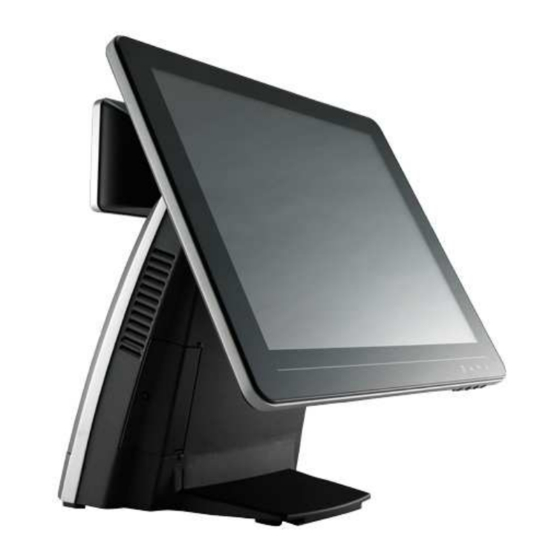
Page 7: A Quick Tour For Ap-3615
AerPOS Series AP-3615 A Quick Tour for AP-3615 15” Touch Display Validation Hole (Cool Air in) Power Switch HDD LED Smart Management Button USB Port Display OSD Power Switch / Status Validation Hole Blue LED: Power ON (Hot Air Out) -
Page 8: Ap-3615 Dimension
AerPOS Series AP-3615 AP-3615 Dimension H: 360mm W: 370mm W: 240mm D: 235mm... -
Page 9: Rear I/O Panel Connectivity
AerPOS Series AP-3615 Rear I/O Panel Connectivity Power USB COM 5 COM 1 COM 3 COM1 Status DC Out Cash COM2 DC IN COM 2 COM 4 Mic In Line Out Status Drawer I/O Port Connector Type Description D-sub 15... -
Page 10: Aer Pos Ap-3615 Packing List
AerPOS Series AP-3615 Before you unplug the power USB cable from I/O panel, please ensure unplug the A/C Cord in advanced. Aer POS AP-3615 Packing List Standard Optional & Peripherals 15” AP-3615 AerPOS Touch Terminal Optional IO Board 12V 150W Power Adaptor... -
Page 11: Hardware Installation And Upgrading
AerPOS Series AP-3615 Do not remove the Display Module without switch off the terminal. Power must be switched off and power cord must be unplugged. Every time you service the system, please be aware of this. 2.5” Hard Disk Drive Installation 1. -
Page 12: Msr / Finger Print Reciever / Rfid / Ibutton Installation
AerPOS Series AP-3615 MSR / Finger Print Reciever / RFID / iButton Installation 1. Remove the plastic cover at the back of Touch Display Module 2. Insert the MSR / RFID / Finger Print Receiver / I- button Module into USB A- Type Connector. -
Page 13: Mb / Heatsink & Smart Fan / Memory Installation
AerPOS Series AP-3615 MB / Heatsink & Smart Fan / Memory Installation 1. Remove back cover of the terminal by two screws on the top side. 2. Anther two screws at the both side of MB Module should be removed for the further disassembly. -
Page 14: Memory (Ddriii Ram) & Cpu Installation / Mb Pin Define, Battery And Clear Cmos Setting
AerPOS Series AP-3615 4. During the MB installation, Please Make sure the MB Golden finger is well connected with IO Board Slot. Memory (DDRIII RAM) & CPU Installation / MB Pin Define, Battery and Clear CMOS Setting Disassembly the MB Module, then Memory installation can be done from the top side of MB Module. -
Page 15: Com Port Power Setting
AerPOS Series AP-3615 COM Port Power Setting AP-3615 COM Port Power can adjust via BIOS or Smart Management Tool. 5. COM Port Power Configuration: 6. Advance > Super IO Configuration > Serial Port 1 or 2 Configuration Advance > F81214 Super IO Configuration > Serial Port... -
Page 16: Integrated Vfd / Lcm Installation
AerPOS Series AP-3615 Integrated VFD / LCM Installation 1. Remove the VFD Plastic cover from the terminal 2. Connect the COM 3 internal cable between Terminal and VFD / LCM Module and install the VFD/ LCM module with Terminal. Fasten one screw back and make sure VFD/LCM module is fixed. -
Page 17: 15" / 11.6" 2 Nd Display Installation
Remove the VFD plastic cover Assemble the 2 screen with bracket with 4 screws Assemble the 2 Screen with bracket to Terminal. Fasten 3 screws (1 on top, 2 underneath) Connect the monitor to AP-3615 by VGA & DC cable... -
Page 18: St Touch Display Installation & Swapping
AerPOS Series AP-3615 15” 1 Touch Display Installation & Swapping Release 1 thumb screw at the back side of Display Lift the Display Module up to disassemble from the main unit of terminal Display and main body units are separated. -
Page 19: Osd Function And Adjustment
AerPOS Series AP-3615 OSD Function and Adjustment OSD function and adjustment Back Light Power (finger touch for 5 seconds) Back Light Power On – Blue LED indication Back Light Power Off – LED indication P-CAP Touch re-calibrates during Power Off and On... -
Page 20: Cash Drawer Installation
AerPOS Series AP-3615 Cash Drawer Installation Before connecting the cash drawer to the AP-3615, please make sure the drive voltage and cable pin assignment of the cash drawer matches the definition of the cash drawer port of AP-3615. Power USB... -
Page 21: Software Installation And Setup
AerPOS Series AP-3615 AP-3615 comes with a variety of drivers for different operating systems. You can download all the necessary drivers and utilities from http://www.fecpos.com. Or send an e-mail to the Customer Service Department of FEC for further assistance. -
Page 22: Chipset Driver Installation
AerPOS Series AP-3615 Chipset Driver Installation Intel Chipset Installation Utilities for Windows XP 1. Download drivers from website or insert the Driver CD into your CD ROM Drive. 2. Execute Setup.exe and Click Next. 3. Read the License Agreement and click Yes & Click Next and the drivers for the Intel Chip set will install. -
Page 23: Intel Chipset Installation Utilities For Windows 7
AerPOS Series AP-3615 Intel Chipset Installation Utilities for Windows 7 1. Download drivers from website or insert the Driver CD into your CD ROM Drive. 2. Execute Setup.exe and Click Next. 3. Read the License Agreement and click Yes & Click Next and the drivers for the Intel Chip set will install. -
Page 24: Net Framwork 3.0 Tool Installation
AerPOS Series AP-3615 .Net Framwork 3.0 Tool Installation .Net Framework 3.0 Tool for Windows XP 1. Download drivers from FEC website or insert the Driver CD into your CD ROM Drive. 2. Double click Setup.exe, and Click Next to start tool installation... - Page 25 AerPOS Series AP-3615 4. choose I have read and ACCEPT the terms of the license Agreement and click Install for the following steps 5. Click the message pop out to check for the detail process. Finally, click Exit to finish the...
-
Page 26: Vga Driver Installation
AerPOS Series AP-3615 VGA Driver Installation VGA driver installation for Windows XP 1. Download drivers from website or insert the CD into your CD ROM Drive. 2. Execute Steup.exe 3. Select Next and click Yes of License Agreement Page. 4. Select Next to continue driver installation. - Page 27 AerPOS Series AP-3615 5. Finally, Finish and Restart the system...
-
Page 28: Vga Driver Installation For Windows 7
AerPOS Series AP-3615 VGA driver installation for Windows 7 1. Download drivers from website or insert the CD into your CD ROM Drive. 2. Execute Steup.exe and select Next 3. Click Yes of License Agreement Page. 4. Select Next to continue driver installation. - Page 29 AerPOS Series AP-3615 5. Finally, Finish and Restart the system...
-
Page 30: Intel Management Engine Components Driver Installation
AerPOS Series AP-3615 Intel Management Engine Components Driver Installation VGA driver installation for Windows 7 1. Download drivers from website or insert the CD into your CD ROM Drive. 2. Execute Steup.exe 3. Select Next and click Yes of License Agreement Page. - Page 31 AerPOS Series AP-3615 5. Finally, Finish and Restart the system...
-
Page 32: Lan Driver Installation
AerPOS Series AP-3615 LAN Driver Installation Realtek RT8111E LAN Driver Installation for Windows XP 1. Download drivers from website or insert the CD into your CD ROM Drive. 2. Execute Setup.exe. 3. Click Next to continue 4. Click Finish to complete the installation procedure. -
Page 33: Realtek Rt8111E Lan Driver Installation For Windows 7
AerPOS Series AP-3615 Realtek RT8111E LAN Driver Installation for Windows 7 1. Download drivers from website or insert the CD into your CD ROM Drive. 2. Execute Setup.exe. 3. Click Next to continue and Finish to complete the installation procedure. -
Page 34: Audio Driver Installation
AerPOS Series AP-3615 Audio Driver Installation Realtek ALC887 Audio Driver Installation for Windows XP & Windows 7 1. Download drivers from website or insert the CD into your CD ROM Drive. 2. Double click Setup.exe, and Click Next to continue... -
Page 35: Fec Project - Capacitive Touch Utility (Raydium Controller)
AerPOS Series AP-3615 FEC Project – Capacitive Touch Utility (Raydium Controller) FEC Projective – Capacitive Touch Utility Introduces: 1. Activate Calibration 2. Mode of FEC Capacitive Touch Panel and default settings 3. Capacitive Touch User Configuration 4. F/W Reading or F/W Update 5. - Page 36 AerPOS Series AP-3615...
- Page 37 AerPOS Series AP-3615 Mode of FEC P-Capacitive Touch Panel and Default Settings The default setting of FEC P-CAP touch will be always “Mouse Mode” with Single Touch as the factory default setting. If the application requires Multi Touch (Dual Touch), FEC P- CAP touch can also be accordingly set as “Touch Mode”...
- Page 38 AerPOS Series AP-3615 3. Default setting includes: Default mode: Mouse Mode Default Sensitivity: 20 Assist Double Click (Pixel): 30 pixel square; Right Click delay: 2 seconds Click Response Time: 5 Initial Contact: 30 FW Version: 130327A1...
- Page 39 AerPOS Series AP-3615 P-Capacitive Touch User Configuration The P-Capacitive Touch is relating to humidity of environment, humidity of finger tips or touching area size of finger tips. Moreover, these facts are relating with personal experience. If user requires a slightly different touch performance, it can be adjusted from the user configuration of touch utility.
- Page 40 AerPOS Series AP-3615 5. Initial Contact (The initial time after re-upload the F/W from utility): this value is from 1~250 seconds (Note: the most optimized Initial Time is “30” seconds) 6. Tick to enable the right click function. 7. After choose the right setting, click “Apply” to finalize the settings.
- Page 41 AerPOS Series AP-3435 F/W Reading and F/W Update 1. Execute the touch utility 2. Choose “Auto Detect” wait for 10 sec for connection between Touch Utility and Touch Controller, until Mouse / Touch Mode shown. You can read the current F/W version (XXXXXXA1) from the bottom of the utility.
- Page 42 AerPOS Series AP-3615 5. wait for 10~20 second for updating F/W; click “OK” when pops out updates firmware finish window. 6. Re-confirm the F/W is updated: click auto detect to re-check the proper firmware is updated.
- Page 43 AerPOS Series AP-3615 Touch Function for 2 Screen The current Raydium touch firmware (130327A1) can only support 2 touch screen in touch mode Win7 or POSReady 7 OS. The function of “Second Display” from this utility is not available for winXP or POSReady2009.
-
Page 44: Eeti Touchkit Tools Installation
AerPOS Series AP-3435 EETI TouchKit Tools Installation EETI TouchKit Installation for Windows XP 1. Down load Touch Kit for WinXP from FEC website or Driver CD 2. Execute Setup.exe 3. Click Next 4. Choose “None” and Click Next for further installation process... - Page 45 AerPOS Series AP-3615 5. Click OK to close the pop-up dialog. 6. Click “Support Multi-Monitor System” and then Next to continue. 7. Click Next and choose a program folder to “Touch Kit”, then “Next” 8. Touch Controller found in USB, then Click Yes...
- Page 46 AerPOS Series AP-3615 9. Click OK and turn off the computer to restart your system again. After the system finish rebooting follow the instruction to calibrate the Touch screen.
-
Page 47: Eeti Touchkit Installation For Windows 7
AerPOS Series AP-3615 EETI TouchKit Installation for Windows 7 1. Down load Touch Kit for Win 7 from FEC website or Driver CD 2. Execute Setup.exe 3. Click Next 4. Un-tick “Install RS232 interface driver” and Click “Next” to go for further process. - Page 48 AerPOS Series AP-3615 5. Click “Yes” and confirm the USB touch controller is plugged. 6. Click “Support Multi-Monitor System” and then Next to continue. 7. Click Next...
- Page 49 AerPOS Series AP-3615 8. Click OK and turn off the computer to restart your system again. After the system finish rebooting follow the directions to calibrate the Touch screen.
-
Page 50: Touchkit Control Panel
AerPOS Series AP-3615 TouchKit Control Panel This section explains the different options in the TouchKit control Panel. General tab The general tab allows you to: • Manage the touch screen controller you installed. Tools tab The tools tab allows you to: •... -
Page 51: Wireless Lan Driver Installation
AerPOS Series AP-3615 Wireless LAN Driver Installation Wireless LAN Driver Installation for all Windows Operating Systems (Optional) 1. Download drivers from website or insert the CD into your CD ROM Drive. 2. Run Setup.EXE 3. Click Next 4. Click Next... -
Page 52: Specifications
AerPOS Series AP-3615 AP-3615 Specifications Aer POS AP-3615 Performance Chipset Intel Sandy Bridge H-61 Intel Dual Core Celeron G540 2.5G Processor Intel i3 2120 3.3G Intel i5 2400S 2.5G DDR3 Standard 2GB, Memory Main Max 8GB Specifications Power Supply 12V 150W... -
Page 53: Troubleshooting
AerPOS Series AP-3615 Please note that the following troubleshooting guide is designed for engineer who has strong computer hardware knowledge or Engineers and Maintenance. Touch Panel Does Not Work Check “Touch Display Module” is connected well with terminal. Check HID USB touch device is detected by OS. -
Page 54: Lan Is Not Functioning Properly
AerPOS Series AP-3615 LAN Is Not Functioning Properly Check if the LAN driver is installed properly. Check if there are any IRQ conflicts. Check if the RJ45 cable is properly connected. The on-board LAN chip could be defective. COM1 ~ COM5 Are Not Functioning Properly Check if the I/O ports are enabled in the CMOS setup. -
Page 55: Smart Management Tool User Guide
(Windows XP & Windows 7 only) 2. Double click the .exe file to activate Smart Management as the following picture. 3. Press the Smart Management button aside the AP-3615 for 5 seconds to enter the Terminal Status. (This button is just above the external USB connector, Please make... - Page 56 (AerPOS only) Total Back Light Hour Show the time the backlight has been used (AerPOS only) Each data would be recorded after the system is shutdown normally, for any incorrect operation or force shutdown, only Abnormal On/Off Count & ON/OFF Total will be recorded, the rest data will missed.
- Page 57 Shows the voltage of DC-IN (If the data is too low, please check the power adaptor) DC In-Current Shows the current of 12V DC-IN(If the data is too low, please check the power adaptor) DC in-Power Shows the power consumption of AP-3615 or BP-500 Consumption...
- Page 58 3 settings could be accessed by the user. a. COM Port Voltage Setting: Please ensure this setting must be operated by the engineer who with strong knowledge of AerPOS & BP-500 and its devices. Inappropriate operation might cause the damage of the powered devices.
- Page 59 AerPOS Series AP-3615 b. Apply the change by click the icon 3rd Step 3rd Step 3rd Step 3rd Step c. Double confirm to apply this change 4th Step...
- Page 60 AerPOS Series AP-3615 d. Shutdown the system and proceed the cold reboot 8. User could enable/disable the OSD function by select following options. After apply the setting, A cold reboot is required.
Need help?
Do you have a question about the AP-3615 and is the answer not in the manual?
Questions and answers