Table of Contents
Advertisement
Quick Links
INSTALLATION AND OPERATION INSTRUCTIONS
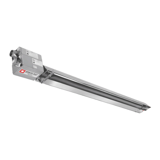
INFRARED RADIANT IP55 POULTRY TUBE HEATER
Single Stage Pull Through System (Negative Pressure)
OWNER / INSTALLER: For your safety this manual must be carefully and thoroughly read and understood before
installing, operating or servicing this heater. This heater is intended for use with either Natural Gas or Propane
Gas. It must be installed by a qualified service person or a licensed contractor in accordance with state and local
codes.
▲WARNING: Improper installation, adjustment, alteration, service, or maintenance can cause property damage,
injury or death. Read the installation, operation and maintenance instructions thoroughly before installing or
servicing this equipment. For assistance or additional information, consult a qualified installer, service agency or
the gas supplier.
INSPECT all combustion air openings into the building and, if necessary, clear as they become blocked by litter,
INSPECT
INSPECT
INSPECT
dust, feathers or other matter.
FOR
FOR
FOR YOUR SAFETY:
FOR
YOUR SAFETY:
YOUR SAFETY: Exhaust fans MUST
YOUR SAFETY:
avoid a high concentration of carbon monoxide. When used without fresh air, this heater may give off carbon
monoxide, an odorless and poisonous gas. CARBON MO
carbon monoxide poisoning resemble the flue with headaches, dizziness and nausea. If you experience these
signs, GET FRESH AIR IMMEDIATELY!
GET FRESH AIR IMMEDIATELY! Have the heaters serviced as soon as possible and check the ventilation in
GET FRESH AIR IMMEDIATELY!
GET FRESH AIR IMMEDIATELY!
the house.
These heaters are designed for agricultural applications and may operate with the use of either Natural Gas or
Liquid Propane (LP) Gas. Check the heater's nameplate to determine the correct gas type before proceeding
with installation.
!INSTALLER: This manual is the property of the owner. Please present this manual to the owner when you leave
the job site.
IF YOU SMELL GAS:
! ! ! ! DO NOT
DO NOT try to light any appliance.
DO NOT
DO NOT
! ! ! ! DO NOT
DO NOT
DO NOT
DO NOT touch any electrical switch; DO NOT
telephone in your building.
! ! ! ! IMMEDIATELY
IMMEDIATELY call your gas supplier from a neighbor's
IMMEDIATELY
IMMEDIATELY
telephone. Follow the gas supplier's instructions. If you
cannot reach your gas supplier, call the fire department.
!IMPORTANT: SAVE THIS MANUAL FOR FUTURE REFERENCE.
!IMPORTANT:
!IMPORTANT:
!IMPORTANT:
Phone 01473 830551 Fax: 01473 832055 E-mail:
Models: SBF 25 - IP55
MUST
MUST be operating on an appropriate cycle when heaters are operating to
MUST
CARBON MONOXIDE POISONING MAY LEAD TO DEATH
NOXIDE POISONING MAY LEAD TO DEATH. Early signs of
CARBON MO
CARBON MO
NOXIDE POISONING MAY LEAD TO DEATH
NOXIDE POISONING MAY LEAD TO DEATH
FOR YOUR SAFETY
FOR YOUR SAFETY
FOR YOUR SAFETY
FOR YOUR SAFETY
DO NOT use any
DO NOT
DO NOT
SAVE THIS MANUAL FOR FUTURE REFERENCE.
SAVE THIS MANUAL FOR FUTURE REFERENCE.
SAVE THIS MANUAL FOR FUTURE REFERENCE.
Gas Fired Products (UK) Ltd.
Gas Fired Products (UK) Ltd.
Gas Fired Products (UK) Ltd.
Gas Fired Products (UK) Ltd.
Chapel Lane, Claydon, Ipswich, Suffolk IP6 0JL, England
info@spaceray.co.uk www.spaceray.com.uk
DO NOT
DO NOT store or use gasoline or other
DO NOT
DO NOT
store or use gasoline or other
store or use gasoline or other
store or use gasoline or other
flammable vapors and liquids in the vicinity of
flammable vapors a
nd liquids in the vicinity of
flammable vapors a
flammable vapors a
nd liquids in the vicinity of
nd liquids in the vicinity of
this or any other appliance.
this or any other appliance.
this or any other appliance.
this or any other appliance.
Form #44201200
July 2012
July 2012
July 2012
July 2012
Advertisement
Table of Contents

Related Manuals for Space-Ray SBF 25


Summary of Contents for Space-Ray SBF 25
- Page 1 INFRARED RADIANT IP55 POULTRY TUBE HEATER Single Stage Pull Through System (Negative Pressure) Models: SBF 25 - IP55 OWNER / INSTALLER: For your safety this manual must be carefully and thoroughly read and understood before installing, operating or servicing this heater. This heater is intended for use with either Natural Gas or Propane Gas.
-
Page 2: Table Of Contents
General Information .......................... 2 4.0) Minimum Clearances to Combustibles................... 3 5.0) Specifications ............................. 4 6.0) Packing List – SBF 25 – IP55 ......................4 6.1) Accessory Packages .......................... 6 7.0) Typical Assembly Layouts ......................... 7 8.0) Dimensions – Models SBF 25-6M ....................8 8.1) -
Page 3: Safety
Ventilation requirements are addressed further in these instructions. Although these heaters may be used in many applications other than space heating (e.g., process heating), Space-Ray will not recognize the warranty for any use other than space heating. This heater is not an explosion proof... -
Page 4: Minimum Clearances To Combustibles
Ends Ends Model No. Model No. Sides Sides Ceiling Ceiling Below Below Ends Ends SBF 25 36” (91cm) 12” (30cm) 69” (175cm) 32” (81cm) Fig. Fig. Fig. Fig. 1 1 1 1 ▲WARNING: ▲WARNING: ▲WARNING: ▲WARNING: Certain materials or objects, when stored under the heater, will be subjected to radiant heat and... -
Page 5: Specifications
Flue Size Ø100mm Minimum Recommended 4.0m Mounting Height 6.0) PACKING LIST – SBF 25 – IP55 A. A. A. A. S S S S BF 25 BF 25 BF 25 - - - - IP55 BF 25 IP55 IP55 Main Body... - Page 6 MODEL NO. MODEL NO. MODEL NO. PART NO. PART NO. PART NO. PART NO. SBF 25-N - IP55....#44473000 SBF 25-L - IP55..... #44473500 Fig. Fig. Fig. Fig. 2 2 2 2 COMPLETE MODEL SYSTEM - - - - Includes...
-
Page 7: Accessory Packages
STANDARD/OPTIONAL ACCESSORIES Part Part # # # # Description Description Part Part Description Description 44129500 Kit, Fresh Air Intake – Ceiling 44129510 Kit, Fresh Air Intake – Sidewall (includes 100mm vent cap) 43341000 Kit, Reflector End Panels (packaged with control box) 2160 Manual Cut Off Valve 4262504... -
Page 8: Typical Assembly Layouts
EMITTER TUBE LENGTH SYSTEM LENGTH* SYSTEM LENGTH* SYSTEM LENGTH* SYSTEM LENGTH* Sections Sections Sections Sections SBF 25-6 3m (2 each) *Plus U-Bend LEGEND NOTES: NOTES: NOTES: NOTES: 1. A U-Bend is used as shown above to create a “U” configuration. -
Page 9: Dimensions - Models Sbf 25-6M
8.0) DIMENSIONS – MODELS SBF 25-6M Fig. 4 Form #44201200 July 2012... -
Page 10: Heater Assembly - Typical Overview (6M System Shown)
8.1) HEATER ASSEMBLY – TYPICAL OVERVIEW (6M SYSTEM SHOWN) Fig. Fig. Fig. Fig. 5 5 5 5 Form #44201200 July 2012... -
Page 11: Typical Suspension Methods
5. Heaters must not be supported by gas or electric supply lines and must be suspended from a permanent structure with adequate load capacity. Space-Ray recommends that the body sections be suspended using chains with turnbuckles. This will allow slight adjustments after assembly and heater expansion/ contraction during operation. -
Page 12: Assembly Of Tube Sections
10.0) ASSEMBLY OF TUBE SECTIONS During field assembly of the heater body sections, the recommended procedure is as follows: A. Before hanging heater sections, first determine the actual layout of the system (see Sections 7.0) for details). Consideration must also be taken for flue pipe, fresh air ducting, gas piping, clearances to combustibles, etc. -
Page 13: 10.1) Assembly Of U-Bend
10.1) ASSEMBLY OF U-BEND 1. Slide the U U U U - - - - bend bend bend onto ends of each tube bend tube tube, ensuring that they are fully engaged. Fasten the U U U U - - - - bend tube bend bend... -
Page 14: Adding Main Body Reflectors
10.2) ADDING MAIN BODY REFLECTORS 1. Place a main body reflector reflector over one of the heater tubes. Squeeze reflector reflector inward slightly and rotate until reflector reflector reflector reflector the edge flange engages with the divider clip of each hanger bracket as shown in DETAIL DETAIL DETAIL DETAIL- - - - B. -
Page 15: Adding U-Bend Reflectors
10.3) ADDING U-BEND REFLECTORS 1. Place the U U U U - - - - bend reflector bend reflector over the main body reflectors. Adjust the overlap to 12” (25cm) as shown. Secure bend reflector bend reflector the U U U U - - - - bend reflector bend reflector bend reflector bend reflector to the main body reflectors with (2) #10 x ½”... -
Page 16: Adding End Reflectors
10.4) ADDING END REFLECTORS Place each end reflector end reflector end reflector end reflector flush with the main body reflectors. Secure by sliding speed clips onto the end reflector reflector edges. Evenly space the speed clips on the sides (two each side) and top (two each) of the reflector reflector reflectors to provide a snug fit. -
Page 17: Inserting Turbulators - Exhaust Tube
Note: Note: Note: Note: Refer to the table below for quantities of turbulators turbulators turbulators turbulators required for each heater model. 610mm Turbulator MODEL Sections SBF 25 Fig. 12 Form #44201200 -16- July 2012... -
Page 18: Attaching Control Box Assembly
11.0) ATTACHING CONTROL BOX ASSEMBLY Warning: Lights Must Face Down. Failure to do so will result in overheating the ignition module and will invalidate the warranty. Fig. Fig. Fig. Fig. 13 1. Place a Torctite Coupling over the end of the Radiant Tube (see Fig. 13) ensuring that it engages fully, up to the stop. -
Page 19: Attaching Fan Assembly
12.0) ATTACHING FAN ASSEMBLY Fig. Fig. Fig. Fig. 16 1. Assemble the Fan Assembly to the Radiant Tube and position the fan outlet pointing downwards for flueless applications. Secure the Fan Assembly to the Radiant Tube by tightening the set screw, taking care to support the Fan Assembly in line with the axis of the tube. - Page 20 7. Tube heaters will expand/contract during operation. Use an approved flexible connector for connections between the rigid piping and the heater. A union should be installed before the control box inlet. An approved shut off valve should be installed within 1.8m of the union. 8.
-
Page 21: Instructions For Pressure Test Gauge Connection
The gas pipe, flexible hose and connections must be self-supporting. The gas pipe work must not bear any of the weight of the heater or any other suspended assembly. 12. Natural Gas - G20 at 20mbar nominal supply pressure (appliance cat 2H). Maximum supply pressure (Pmax) 25mbar Minimum supply pressure (Pmin) - Page 22 category 2H: gas type G20 (natural): supply pressure 20mbar nom 17mbar min 25mbar max category 3P: gas type G31 (propane): supply pressure 37mbar nom 27mbar min 45mbar max 3. Switch off the electricity supply to the appliance open the control box door and remove the manometer tube from the LEFT (Gas IN) control valve test nipple.
-
Page 23: Electrical Connections
STEP O STEP OPENING PRESSURE SETTING PENING PRESSURE SETTING STEP O STEP O PENING PRESSURE SETTING PENING PRESSURE SETTING 1. Switch off the electricity to the appliance, open the control box door and locate the step opening setting dial (see Fig. 22). 2. - Page 24 The diagram below shows a field supplied IP55 junction box for connecting the power to the fan. Fig. 24 Fig. 24 Fig. 24 Fig. 24 2. Twin core and earth PVC covered flexible supply cable (0.5mm 2-to National or Local standard specification) must be used, with connection made as follows: Single Heaters per Thermostat connection diagram Single Heaters per Thermostat connection diagram...
-
Page 25: Venting And Fresh Air For Combustion
3. Internal Wiring Diagram Fig. Fig. Fig. Fig. 27 16.0) VENTING AND FRESH AIR FOR COMBUSTION POISONOUS GAS AND SOOT HAZARD These appliances may be installed with an exhaust flue fitted or or or or without an exhaust flue fitted. A. - Page 26 Ventilation may be achieved by any of the three following different means: Thermal evacuation of the products of combustion/air mixture Mechanical evacuation of the products of combustion/air mixture Natural air change VENTILATION BY THERMAL EVACUATION VENTILATION BY THERMAL EVACUATION VENTILATION BY THERMAL EVACUATION VENTILATION BY THERMAL EVACUATION 1.
- Page 27 F F F F lue, lue, m ( m (Ø100mm Ø100mm) ) ) ) Ø100mm Ø100mm lue, lue, Ø100mm Ø100mm -1.7m SBF 25 -1.7m IP55 -1.7m Fig. 28 Fig. 28 Fig. 28 Fig. 28 Type A2: Type A2: Type A2: Type A2: Outside (ducted) combustion air supply.
- Page 28 Vertical Through the roof (Part No. 30676040) Horizontal Through Sidewall (Part No. 30675020) Fig. Fig. 29 Fig. Fig. Form #44201200 July 2012 -27-...
- Page 29 Alternative Taking Fresh Air from the Attic (Part No. 44129000) Step A (Part No. 30675020) Note: This hole location should allow the hose enough room to expand and contract with the heater. (Part No. 30504040) Step B (End View) (Part No. 30676040) Step D Step E Silicon joints.
-
Page 30: Lighting And Shutdown Instructions
Type C52: Type C52: Type C52: Type C52: When fresh air for combustion and the flue outlet are from different pressures zones as shown in Fig. 28, the flue outlet and the fresh air intake must not be on surfaces that are 180 degrees apart. The acceptable configurations are those shown in Fig. -
Page 31: Commissioning
18.0) COMMISSIONING The chart below shows the sequence of operation for the normal operating cycle. Fig. 29 Fig. 29 Fig. 29 Fig. 29 If the flame is not sensed during sequence T3 then the heater will go to lockout. It is essential that all new pipework installations are purged and tested for soundness with a suitable leak detection fluid prior to attempting to ignite any appliance. -
Page 32: Cleaning And Annual Maintenance
IGNITION IGNITION IGNITION IGNITION 1. To shut down the appliance for short periods of time, switch off the electricity supply to the appliance. 2. To shut down the appliance for a period for time in excess of one week, switch off the electricity supply to the appliance and turn off the gas supply at the gas isolation valve. - Page 33 Venting System: Venting System: Venting System: Venting System: Disconnect vent pipe and inspect internally using a flashlight to make sure no foreign • • • • material has collected in the pipes. Check the external vent cap and make sure that there is no obstruction around the exhaust openings.
-
Page 34: Troubleshooting Guide
20.0) TROUBLESHOOTING GUIDE Form #44201200 July 2012 -33-... - Page 35 Form #44201200 -34- July 2012...
-
Page 36: Replacing Parts
21.0) REPLACING PARTS ELECTRIC SHOCK & EXPLOSION HAZARD Only use genuine Space-Ray replacement parts. Parts are available from the factory for replacement by a licensed person. Refer to the Replacement Parts Guide in Section 24.0) for all replacement parts. IMPORTANT:... -
Page 37: Removing Main Burner
21.2) REMOVING MAIN BURNER Fig. 3 Fig. 3 Fig. 3 Fig. 32 2 2 2 1. Open the control box door; unscrew the two M4 x 25 setscrews from the Burner Bracket and remove the Burner Clamp. 2. Unscrew the Burner from the Injector Fitting 3. -
Page 38: Removing Ignition Control
21.4) REMOVING IGNITION CONTROL Fig. 3 Fig. 3 Fig. 3 Fig. 34 4 4 4 1. Disconnect the 12 way Molex electrical connector and the grey HT ignition spark/flame sensor lead from the Ignition Control. 2. Unscrew the M3 screw securing the Ignition Control to the Control Valve. 3. -
Page 39: Removing Gas Valve And Manifold Assembly
21.6) REMOVING GAS VALVE AND MANIFOLD ASSEMBLY Fig. 3 Fig. 36 6 6 6 Fig. 3 Fig. 3 1. After opening the control box door, disconnect the 12 way Molex electrical connector. 2. Disconnect the grey HT ignition spark/flame sensor lead from the ignition module. 3. -
Page 40: Removing Air Inlet Plate
21.8) REMOVING AIR INLET PLATE Fig. 38 Fig. 38 Fig. 38 Fig. 38 1. After opening the control box door, disconnect tubing from both brass pressure test fittings. 2. Remove brass nut from pressure test fitting. 3. Disassemble components from the control box. 21.9) REMOVING THE FAN Fig. -
Page 41: Conversion Instructions
22.0) CONVERSION INSTRUCTIONS CONVERSION FROM CAT. 2H ( CONVERSION FROM CAT. 2H ( CONVERSION FROM CAT. 2H ( CONVERSION FROM CAT. 2H (G20 G20) TO CAT. 3P ( ) TO CAT. 3P ( ) TO CAT. 3P ( ) TO CAT. 3P (G31 G31) ) ) ) 1. -
Page 42: Replacement Parts Guide
Label, Fan/Power Supply 4260420 Label, Warning - GB/IE 43344160GB Label, Clearances to Combustibles 42848130GB Label, Nameplate 4260440 Label, Operating Instructions - GB 4262000 Label, Space-Ray Logo 4260625A Label, “This Way Up” 43269050 Label, Door Remains Closed 42874070 Label, Wire Connections 44201200... - Page 43 Minimum Clearances to Combustibles All dimensions in centimetres PIN 87BT24 THIS WAY UP LIGHTS TO FACE DOWN Form #44201200 -42- July 2012...
- Page 44 4250937 4250937 4250937 42509378 8 8 8 Fan Fan Assembly Assembly Assembly Assembly Description Description Description Description Item No. Item No. Item No. Item No. Part No. Part No. Part No. Part No. Qty. Qty. Qty. Qty. 4260132 Gasket 44015251 101.6mm Connector (tube flange assembly with set screw) 4267216 M6 Hex Nut...
- Page 45 BODY COMPONENTS BODY COMPONENTS BODY COMPONENTS BODY COMPONENTS I I I I tem Part No. Part No. Part No. Part No. Description Description Description Description Qty. Qty. Qty. Qty. No..02127110 Hex Nut 5/16-18 02125130 Screw #10-24 x ½” Round Head Machine 42769010 Sliding Clamp (reflector) 02189020...
Need help?
Do you have a question about the SBF 25 and is the answer not in the manual?
Questions and answers