Table of Contents
Advertisement
Quick Links
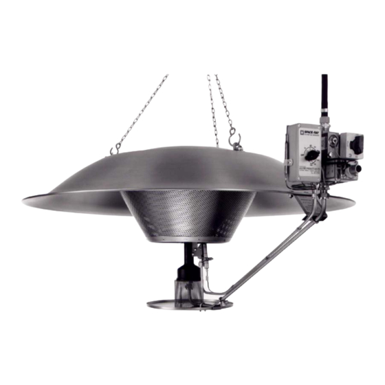
SRB 38 RADIANT BROODER
INSTALLATION AND SERVICING INSTRUCTIONS
This heater is for use with both Natural Gas and Liquid Petroleum Gas. It
must be installed by a Competent Person as stated in the Gas Safety
(Installation and Use) Regulations 1984.
Leave these Instructions with the Person/Department responsible for the
Safe Installation and Operation of the heater.
Gas Fired Products (UK) Ltd.
Chapel Lane, Claydon, Ipswich
Suffolk IP6 0JL, England
Tel: 01473 830551 Fax: 01473 832055
E-mail:
Info@spaceray.co.uk
www.spaceray.co.uk
Advertisement
Table of Contents

Related Manuals for Space-Ray SRB 38


Summary of Contents for Space-Ray SRB 38
- Page 1 SRB 38 RADIANT BROODER INSTALLATION AND SERVICING INSTRUCTIONS This heater is for use with both Natural Gas and Liquid Petroleum Gas. It must be installed by a Competent Person as stated in the Gas Safety (Installation and Use) Regulations 1984.
-
Page 3: Table Of Contents
INSTALLATION, SERVICING AND OPERATING INSTRUCTIONS Before installation, check that the local distribution conditions, nature of gas and pressure, and adjustment of appliance are compatible. INDEX SectionTitle Page Warning Information Technical Data 3 - 4 Specifications Ventilation 3 - 4 Assembling Brooder from Kit Form 4 - 5 Unpacking Emitter to Reflector... -
Page 4: Warning Information
WARNING 1. Warning Information: FOR SAFE AND EFFICIENT OPERATION THIS APPLIANCE NEEDS A FREE SUPPLY OF FRESH AIR. IN THE ABSENCE OF SUFFICIENT OXYGEN CARBON MONOXIDE (C0) WILL BE PRODUCED. CARBON MONOXIDE EVEN IN SMALL CONCENTRATIONS CAN CAUSE DEATH IN ADDITION CONCENTRATION OF CARBON DIOXIDE (CO2) MUST BE LIMITED TO SAFE LEVELS. -
Page 5: Technical Data
It also contains details of the required air flow rate when using mechanical ventilation. If you are in any doubt as to the required ventilation contact SPACE-RAY direct, by telephone or fax. -
Page 6: Assembling Brooder From Kit Form
UNPACKING The Brooder is supplied as follows:- REF: QTY. DESCRIPTION: REFLECTOR HANGING LUG M8 NUT AND WASHER (SHALLOW)M10(DEEP) EMITTER ASSEMBLY HANGING CHAIN SET M6 BOLT, NUT AND WASHER CONTROL ARM ASSEMBLY M5 NUT AND WASHER Page 4 of 10... -
Page 7: Control Arm
3.2. ASSEMBLE EMITTER TO REFLECTOR 3.2.1. Stand Emitter Assembly (4) on bench with M8 (Shallow or M10 (Deep) setscrews (large diameter of cone) uppermost. 3.2.2. Place reflector (1) over Emitter Assembly (4) such that the 3 x M8 (M10) setscrews pass through the 3 holes in the Reflector. -
Page 8: Brooder Ignition
5.0. BROODER IGNITION 5.1. Lighting (All Controls) 5.1.1. Turn on gas taps. 5.1.2. On initial operation, slacken hose connection to control valve inlet and purge air from gas line. Tighten hose connection to control valve inlet. 5.1.3. Ensure all gas connections are sound. N.B. -
Page 9: Mbc And Mod Control
5.3.3. If pilot flame fails to establish after second attempt, refer to fault finding chart. 5.3.4. When pilot flame is established, switch on 24V electrical supply to main burner valve and adjust thermostat to call for heat. Main burner will ignite. 5.4. -
Page 10: 1 Control
6.1.7 Brush both inside and outside surfaces of perforated emitter with large brush to remove any burnt dust particles. 6.2. PILOT - NO. 1 CONTROL 6.2.1 Unscrew pilot burner gas tube nut from jet holder in base of burner frame, and unscrew jet holder from pilot burner frame. -
Page 11: Fault Finding
7. 0 FAULT FINDING PILOT/MAIN BURNER FAILS TO IGNITE 7.1.1. Gas turned OFF. 7.1.2. Blocked pilot/main jet. 7.1.3. Faulty valve. GAS IGNITES BUT FLAME NOT ESTABLISHED 7.2.1. Flame failure valve not depressed correct length of time. 7.2.2. Faulty flame failure valve. 7.2.3. - Page 12 04/02 326S Page 10 of 10...
Need help?
Do you have a question about the SRB 38 and is the answer not in the manual?
Questions and answers