Table of Contents
Advertisement
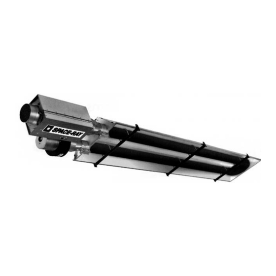
Overhead Radiant Tube Heaters
INSTALLATION, SERVICING AND OPERATING
INSTRUCTIONS
Gas Fired Products (UK) Ltd.
Chapel Lane, Claydon, Ipswich
Suffolk IP6 0JL, England
Tel: 01473 830551 Fax: 01473 832055
E-mail:
info@spaceray.co.uk
www.spaceray.co.uk
CBU09
CBU12
CBU15
SRU25
ERU25
SRU30
SRU35
SRU40
SRU45
SRL09
SRL12
SRL15
SRL25
SRL30
SRL35
SRL40
SRL45
FormForm
Advertisement
Table of Contents

Related Manuals for Space-Ray CBU09


Summary of Contents for Space-Ray CBU09
- Page 1 Overhead Radiant Tube Heaters INSTALLATION, SERVICING AND OPERATING INSTRUCTIONS CBU09 CBU12 CBU15 SRU25 ERU25 SRU30 SRU35 SRU40 SRU45 SRL09 SRL12 SRL15 SRL25 SRL30 SRL35 SRL40 SRL45 Gas Fired Products (UK) Ltd. Chapel Lane, Claydon, Ipswich Suffolk IP6 0JL, England Tel: 01473 830551 Fax: 01473 832055 E-mail: info@spaceray.co.uk...
-
Page 3: Table Of Contents
INSTALLATION, SERVICING AND OPERATING INSTRUCTIONS Before installation, check that the local distribution conditions, nature of gas and pressure, and adjustment of appliance are compatible. INDEX Section Title Page Safety Installer Responsibility Technical Data 3 - 6 Un-Packing 7 - 10 CBU 09/12/15 SRU25 ERU25 SRU 30/35 SRU 40/45 SRL 09/12/15 SRL 25... -
Page 4: Safety
INSTALLATION, SERVICING & OPERATING INSTRUCTIONS 1. SAFETY This heater is a self-contained overhead radiant tube heater designed for non-domestic use. Safety information required during installation and operation of this heater is provided in this manual and the labels on the product. The installation, service and maintenance of this heater must be performed by a contractor qualified in the installation and service of gas fired heating equipment. -
Page 5: Technical Data
3. TECHNICAL DATA Table 1 MODEL CBU09/SRL09-N CBU09/SRL09-L Heat Input 9.0 kW Hs 8.1 kW Hi Appliance Type (II A2, B 2H3+ Appliance Category 2H3+ Adjusted for 2H G20 20mbar 3+ G30/G31 29/37mbar Appliance Type (II A2, B 2H3P Appliance Category... - Page 6 Table 3 MODEL CBU15/SRL15-N CBU15/SRL15-L Heat Input 15. kW Hs 13.5 kW Hi Appliance Type A2, B Appliance Category 2H3+ Adjusted for 2H G20 20mbar 3+ G30/G31 29/37mbar Setting Pressure 12.5mbar None Injector No. 31 Ø1.9mm Pre-injector None None Electrical Supply 230V~50Hz 125W Fuse Externally Dimensions...
- Page 7 Table 5 MODEL SRU30/SRL30-N SRU30/SRL30-L Heat Input 29.2 kW Hs 26.3 kW Hi Appliance Type (II A2, B 2H3+ Appliance Category 2H3+ Adjusted for 2H G20 20mbar 3+ G30/G31 29/37mbar Appliance Type (II A2, B 2H3P Appliance Category 2H3P Adjusted for 2H G20 20mbar 3P G31 37mbar Setting Pressure...
- Page 8 Table 7 MODEL SRU40/SRL40-N SRU40/SRL40-L Heat Input 42.2kW Hs 38.0kW Hi Appliance Type (II A2, B 2H3+ Appliance Category 2H3+ Adjusted for 2H G20 20mbar 3+ G30/G31 29/37mbar Appliance Type (II A2, B 2H3P Appliance Category 2H3P Adjusted for 2H G20 20mbar 3P G31 37mbar Setting Pressure 12.5mbar...
-
Page 9: Un-Packing
UN-PACKING CBU09/12/15 SRU25/ERU25 The appliances are supplied as follows:- Table 9 MODEL CBU09/12/15 SRU/ERU25 Carton (containing the following) Control Box Assembly Fan Assembly U Bend Hanger Bracket Torctite Coupling Fastenings Pack Radiant Tube (Ø76.2 x 4572) Radiant Tube (Ø76.2 x 2285) - Page 10 SRU30/35 SRU40/45 The appliances are supplied as follows:- Table 10 MODEL SRU30/35 SRU40/45 Carton (containing the following) Control Box Assembly Fan Assembly U Bend Hanger Brackets Torctite Coupling Fastenings Pack Radiant Tube (Ø101.6 x 4572) Radiant Tube (Ø101.6 x 1524) Reflector Panel (long) Reflector Panel (short) Reflector End Panel (notched)
-
Page 11: Form 483S Rev Jan
SRL09/12/15 SRL25 The appliances are supplied as follows:- Table 11 MODEL SRL09/12/15 SRL25 Carton (containing the following) Control Box Assembly Fan Assembly Hanger Brackets Torctite Coupling Fastenings Pack Radiant Tube (Ø76.2 x 4572) Reflector Panel (1511 short) Reflector Panel (3035 long) Reflector End Panel SRL09/12/15 Fig 5... -
Page 12: Srl 30/35 Srl 40/45
SRL30/35 SRL40/45 The appliances are supplied as follows:- Table 12 MODEL SRL30/35 SRL40/45 Carton (containing the following) Control Box Assembly Fan Assembly Hanger Brackets Torctite Coupling Fastenings Pack Radiant Tube (Ø101.6 x 4572) Radiant Tube (Ø101.6 x 3048) Radiant Tube Assy (turbulator) Reflector Panel (3035 long) Reflector End Panel SRL30/35... -
Page 13: Installation
IMPORTANT: when 'U' Tube Heaters are angle mounted (fig 9 & 9a) the fan should be assembled to the higher of the two emitter tubes as shown. CBU09/12/15 SRU30/35/40/45 SRL09/12/15/25 SRU25 ERU25 SRL30/35/40/45... - Page 14 5.1.4 The control box must be supported with a welded chain after overall heater suspension is complete. The is to prevent control from sagging and burning tube out prematurely. Assemble bracket and turnbuckle to inlet end of control as shown. 5.1.5 Adjust the turnbuckle until control box is level.
- Page 15 Minimum clearance from combustibles:- ABOVE (CEILING) ABOVE (CEILING) FRONT SIDE SIDE REAR BELOW BELOW Fig. 11 Table 13 MODEL SIDE ABOVE BELOW FRONT REAR CBU09-15/SRL09-15 1220 SRU25/ERU25/SRL25 510mm 450mm 1220mm 510mm 610mm 305mm SRU30-45/SRL30-45 760mm 610mm 2285mm 610mm 760mm 380mm Gas Supply ube heaters will expand and contract during operation.
-
Page 16: Electrical Supply
5.2.1.1 Installation pipes should be fitted in accordance with National and Local Regulations. Pipes of a smaller size than the heater connection (R - ½) should not be used and the pipework must be designed to achieve a gas supply pressure between the maximum and minimum values stated above, measured at the appliance inlet pressure test point. -
Page 17: Electrical Supply
MULTIPLE HEATERS PER THERMOSTAT GREEN/YELLOW BLUE BROWN SWITCH SWITCH THERMOSTAT HEATER 1 HEATER 2 Fig. 12 Notes:-The method of connection to the electrical supply must facilitate complete isolation and should preferably be via a fused double pole isolator having a constant separation of at least 3mm in all poles and supplying the appliance ONLY. -
Page 18: Ventilation
Ventilation POISONOUS GAS AND SOOT HAZARD These appliances may be installed with an exhaust flue fitted or without an exhaust flue fitted. 5.4.1 Flueless (Unflued) The installation room should have a volume of at least 10m³/kw of installed nominal heat input of the radiant heater. -
Page 19: Ventilation
5.4.1.3 Ventilation by Natural Air Change Gas-fired radiant heaters may be operated without any special exhaust system if the exhaust gases are discharged to the outside atmosphere by a sufficient natural air change in the installation room. Furthermore, no provision for thermal or mechanical ventilation is required in the following particular cases: Buildings with natural air change greater than 1.5 volumes per hour Buildings with a density of operating heat input not greater than 5W/m³... - Page 20 Note : first length is parallel section second length is concentric section. Fig. 14 5.4.2.4. Type A Outside (ducted) combustion air supply. When installed in a dusty or polluted atmosphere, the heater should be fitted with a ducted supply of clean fresh air. A length of 100mm flexible ducting should be installed between the Control Box Air Inlet and any rigid ducting and be secured to the Air Inlet with hose clips.
- Page 21 Components M&G PN Description Fig. 15 Form 483S Rev Jan 09 Page 19 of 53...
- Page 22 5.2.4.7. TypeC The following figure shows the typical arrangements for concentric vertical flues, see table 14 for 90° bend equivalent lengths. The bends shown in the illustrations connecting the combustion air intake to the concentric ducts is calculated into the overall length. For example a system with one additional 150/100mm Ø concentric 90°...
-
Page 23: Assembly
ASSEMBLY CBU 09/12/15 Fig. 17 Form 483S Rev Jan 09 Page 21 of 53... - Page 24 6.1.1 Remove the packaging/protection from the Radiant Tubes and ensure that they are clear internally. Place the Radiant Tubes on trestles, providing 150mm minimum clearance above the floor and space 190mm apart with the ends of the tubes in line. Ensure that the welded seam of the tube is in contact with the hanger bracket (see 6.1.2 below) i.e.
- Page 25 6.1.10 Using twin core and earth flexible supply cable, as specified in Section 5.3.2, suitable for 230V~50Hz 125W supply, connect the 3 pin electrical socket provided (fastenings pack) as follows:- Brown (Red) to terminal marked L Blue (Black) to terminal marked N Green/Yellow to terminal marked External fuse rating required - 3A.
- Page 26 SRU25/ERU25 Fig. 18 Form 483S Rev Jan 09 Page 24 of 53...
- Page 27 6.2.1 Remove the packaging/protection from the Radiant Tubes and ensure that they are clear internally. Place the Radiant Tubes on trestles, providing 150mm minimum clearance above the floor and space 190mm apart, with the ends of the tubes in line. Ensure that the welded seam of the tube is in contact with the hanger bracket (see 6.2.2 below) i.e.
- Page 28 6.2.10 Using twin core and earth flexible supply cable, as specified in Section 5.3.2, suitable for 230V~50Hz 125W supply, connect the 3 pin electrical socket provided (fastening pack) as follows:- Brown (Red) to terminal marked L Blue (Black) to terminal marked N Green/Yellow to terminal marked External fuse rating required - 3A...
- Page 29 SRU30 & SRU35 Fig. 19 Form 483S Rev Jan 09 Page 27 of 53...
- Page 30 6.3.1 Remove the packaging/protection from the Radiant Tubes and ensure that they are clear internally. Place the Radiant Tubes on trestles, providing 150mm minimum clearance above the floor and space 305mm apart with the ends of the tubes in line. Ensure that the welded seam of the tube is in contact with the hanger bracket (see 6.3.2 below) i.e.
- Page 31 6.3.6 Position the Reflector End Panel (notched) over the Radiant Tubes and into the end of the Reflector Panel with the End Panel flange flush with the end of the Reflector. Secure the Reflector End Panel to the Reflector Panel by use of 6 - U type speed clips provided (fastenings pack);...
- Page 32 SRU40 & SRU45 Fig. 21 Form 483S Rev Jan 09 Page 30 of 53...
- Page 33 6.4.1 Remove the packaging/protection from the Radiant Tubes (2 long tubes and 2 short tubes) and ensure that they are clear internally. Join one long tube and one short tube together using a Torctite Coupling. Ensure that the tubes engage fully into the Torctite Coupling (up to the stop) and that the welded seam of the tubes is in line from one tube to the other and that the Torctite Coupling clamp is positioned adjacent to the weld seam.
- Page 34 6.4.6 Place the two long Reflector Panels onto the Hanger Brackets and position as shown in Fig 18. Place the short Reflector Panel over the two long Reflector Panels to provide a 50mm overlap at each end. Clamp the long and short Reflector Panels (Control Box end) to the Hanger Bracket at which they overlap, using two retainers and M6 setscrews and washers (fastenings pack).
- Page 35 SRL09/12/15 Fig. 23 Form 483S Rev Jan 09 Page 33 of 53...
- Page 36 6.5.1 Remove the packaging/protection from the Radiant Tube and ensure it is clear internally. The appliance should be assembled prior to being suspended and due consideration must be given to the means by which the appliance is to be safely raised into position. 6.5.2 Place the Radiant Tube on trestles, providing 150mm minimum clearance above the floor and assemble the three Hanger Brackets to the Radiant tube using one U bolt per bracket (fastening pack) and position along the...
- Page 37 6.5.10 Using a suitable cable connector and twin core and earth PVC covered flexible supply cable, (0.5 mm National or Local standard specification) connect the fan leads to the 3 pin plug provided (fastenings pack) as follows:- Brown (red) to terminal marked L Blue (Black) to terminal marked N Green/Yellow...
- Page 38 SRL25 Fig. 24 Form 483S Rev Jan 09 Page 36 of 53...
- Page 39 6.6.1 Remove the packaging/protection from the Radiant Tubes and ensure that they are clear internally. It is recommended that the appliance is suspended in sections which are joined by the use of a Torctite Coupling once in position. Appliances may however, at the discretion of the installation engineer, be assembled (less Reflector Panels) prior to being suspended, in which case due consideration must be given to the means by which the appliance is to be safely raised into position.
- Page 40 6.6.9 If combustion air is to be ducted to the appliance, attach a length of flexible ducting to the Air Inlet Adaptor of the Control Box by use of a suitable hoseclip. Attach the inlet end of the hose to any fixed ducting, also by use of a suitable hoseclip, allowing for adequate movement of the appliance.
- Page 41 SRL30 & SRL35 Fig. 25 Form 483S Rev Jan 09 Page 39 of 53...
- Page 42 6.7.1 Remove the packaging/protection from the Radiant Tubes and ensure that they are clear internally. It is recommended that the appliance is suspended in sections which are joined by the use of a Torctite Coupling once in position. Appliances may however, at the discretion of the installation engineer be assembled (less reflector panels) prior to being suspended, in which case due consideration must be given to the means by which the appliance is to be safely raised into position.
- Page 43 6.7.7 Place two of the Reflector Panels onto the Hanger Brackets and position their outer edges such that they overhang the outer Hanger Brackets by 80mm (see Fig. 25). Place the third Reflector Panel over the two previously positioned Reflector Panels to provide a 50mm overlap at each end. Clamp the first and second Reflector Panels, where they overlap, to the second Hanger Bracket (from Control Box end) using two retainers and M6 setscrews and washers (fastenings pack).
- Page 44 SRL40 & SRL45 Fig. 27 Form 483S Rev Jan 09 Page 42 of 53...
-
Page 45: Fan Assembly
6.8.1 Remove the packaging/protection from the Radiant Tubes and ensure that they are clear internally. It is recommended that the appliance is suspended in sections which are joined by the use of Torctite Couplings once in position. Appliances may however, at the discretion of the installation engineer, be assembled (less reflector panels) prior to being suspended, in which case due consideration must be given to the means by which the appliance is to be safely raised into position. -
Page 46: Assembly
6.8.7 Place the fourth Torctite Coupling over the open end of the Radiant Tube (and turbulator) Assembly carrying the Fan Assembly ensuring that it engages fully, up to the stop. Assemble the previously assembled section of Radiant Tubes into the Torctite Coupling ensuring that it engages fully (up to the stop) and with all the appliance Hanger Brackets correctly aligned with each other (see Fig. -
Page 47: Commissioning
COMMISSIONING It is essential that all new pipework installations are purged and tested for soundness with a suitable leak detection fluid prior to attempting to ignite any appliance. This work should be carried out in accordance with National or Local regulations. N.B. - Page 48 7.3.4.1 Unscrew the sealing screw (two turns) of the LEFT (Gas IN) Control Valve test nipple and connect the free end of the manometer tube (permanently connected to the manometer test nipple inside the rear panel of the control box) to this test nipple (See Fig. 29). Close the control box door and secure with the two toggle latches. 7.3.4.2 Ignite the appliance burner by switching on the electricity supply to the appliance and check that the manometer reading is as stated below for the gas type the appliance is "adjusted for"...
-
Page 49: Air Proving Switch
7.3.5.4 Upon obtaining the correct burner setting pressure switch off the electricity supply to the appliance, remove the screwdriver, replace the plug into the boss in the upper surface of the control box door and open the door. Remove the manometer tube from the RIGHT (Gas OUT) Control Valve test nipple and screw in the test nipple sealing screw. - Page 50 Control Box The control box can be removed from the appliance and serviced at ground level. 8.2.1 Disconnect the electrical supply socket from the 3 pin plug (marked 230V~50Hz) mounted in the side of the Control Box, turn off the gas supply to the appliance at the gas isolation valve and disconnect the gas supply pipe from the control box, leaving the R - ½...
-
Page 51: Servicing
Reflector 8.3.1. If necessary, the Reflector can be dismantled by removing the Clamps, and where applicable the U type speed clips, and sliding the Reflector Panels out of the Hanger Brackets after first removing the Reflector End Panels. Dust accumulated on top of the Reflector should be brushed off and the reflective surface cleaned with a soft cloth and detergent in water. -
Page 52: Electrodes
provides the earth path for the ignition spark. The two electrodes are identical, therefore either lead (grey HT or green/yellow - earth) may be connected to either electrode. 9.2.1 Disconnect the grey HT ignition/flame sensor lead and the green/yellow earth lead from the electrodes by gently pulling the connectors, using pliers. -
Page 53: Twin Solenoid Control Valve
Twin solenoid Control Valve 9.8.1 Remove the Ignition Control (see section 9.3) and the Burner (see section 9.5) and disconnect the gas supply pipe from the Control Box, leaving the R - ½ nipple screwed into the Control Valve elbow flange. Unscrew the two M4 setscrews securing the Valve Bracket to the floor of the Control Box and lift out the Control Valve Assembly. -
Page 54: Operating Instructions
10.1.4 Carry out checks in accordance with Section 7.3 of this manual to ensure correct supply pressure relative to the gas type being used (G30 - Butane or G31 - Propane). 10.2 Conversion from cat 3+ (LPG) to cat 2H (Natural Gas) 10.2.1 Remove the Injector from the Injector Fitting (see Section 9.6) and replace it with the alternative Injector supplied (fastenings pack). - Page 55 NOTES: GB IE (ES IT PT) Form 483S Rev Jan 09 Page 53 of 53...
Need help?
Do you have a question about the CBU09 and is the answer not in the manual?
Questions and answers