Advertisement
Quick Links
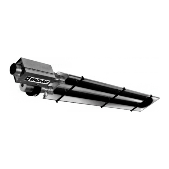
Overhead Radiant Tube Heaters
INSTALLATION, SERVICING AND OPERATING
INSTRUCTIONS
Gas Fired Products (UK) Ltd.
Chapel Lane, Claydon, Ipswich
Suffolk IP6 0JL, England
Tel: 01473 830551 Fax: 01473 832055
E-mail:
info@spaceray.co.uk
www.spaceray.co.uk
SRLP25
SRLP30
SRLP35
SRLP40
SRLP45
SRUP25
SRUP30
SRUP35
SRUP40
SRUP45
Advertisement

Related Manuals for Space-Ray SRLP25


Summary of Contents for Space-Ray SRLP25
- Page 1 Overhead Radiant Tube Heaters INSTALLATION, SERVICING AND OPERATING INSTRUCTIONS SRLP25 SRLP30 SRLP35 SRLP40 SRLP45 SRUP25 SRUP30 SRUP35 SRUP40 SRUP45 Gas Fired Products (UK) Ltd. Chapel Lane, Claydon, Ipswich Suffolk IP6 0JL, England Tel: 01473 830551 Fax: 01473 832055 E-mail: info@spaceray.co.uk...
- Page 3 INSTALLATION, SERVICING AND OPERATING INSTRUCTIONS Before installation, check that the local distribution conditions, nature of gas and pressure, and adjustment of appliance are compatible. INDEX Section Title Page Technical Data 2 - 4 Un-Packing 5 - 8 SRUP 25 SRUP 30/35 SRUP 40/45 SRLP 25 SRLP 30/35 SRLP 40/45 Installation...
- Page 4 Page 2 of 48...
-
Page 5: Technical Data
INSTALLATION, SERVICING & OPERATING INSTRUCTIONS TECHNICAL DATA Table 4 MODEL SRU25/SRL25/ERU25-N SRU25/SRL25/ERU25-L Heat Input 23.0 kW Hs 20.7 kW Hi Appliance Type Appliance Category 2H3+ Adjusted for 2H G20 20mbar 3+ G30/G31 29/37mbar Setting Pressure 12.5mbar None Injector Ø3.8mm Ø2.3mm Pre-injector None None... - Page 6 Table 7 MODEL SRU40/SRL40-N SRU40/SRL40-L Heat Input 42.2kW Hs 38.0kW Hi Appliance Type Appliance Category 2H3+ Adjusted for 2H G20 20mbar 3+ G30/G31 29/37mbar Setting Pressure 12.5mbar None Injector ø5.0mm ø3.2mm Pre-injector None None Electrical Supply 230V~50Hz 125W Fuse Externally Dimensions SRU40: 6.97m x 0.715m SRL40: 13.00m x 0.34m...
- Page 7 UN-PACKING CBU09/12/15 SRU25/ERU25 The appliances are supplied as follows:- Table 9 MODEL CBU09/12/15 SRU/ERU25 Carton (containing the following) Control Box Assembly Fan Assembly U Bend Hanger Bracket Torctite Coupling Fastenings Pack Radiant Tube (Ø76.2 x 4572) Radiant Tube (Ø76.2 x 2285) Reflector Panel (2540 long) Reflector End Panel (notched) Reflector End Panel (Plain)
- Page 8 SRU30/35 SRU40/45 The appliances are supplied as follows:- Table 10 MODEL SRU30/35 SRU40/45 Carton (containing the following) Control Box Assembly Fan Assembly U Bend Hanger Brackets Torctite Coupling Fastenings Pack Radiant Tube (Ø101.6 x 4572) Radiant Tube (Ø101.6 x 1524) Reflector Panel (long) Reflector Panel (short) Reflector End Panel (notched)
- Page 9 SRL09/12/15 SRL25 The appliances are supplied as follows:- Table 11 MODEL SRL09/12/15 SRL25 Carton (containing the following) Control Box Assembly Fan Assembly Hanger Brackets Torctite Coupling Fastenings Pack Radiant Tube (Ø76.2 x 4572) Reflector Panel (1511 short) Reflector Panel (3035 long) Reflector End Panel SRL09/12/15 Fig 5...
- Page 10 SRL30/35 SRL40/45 The appliances are supplied as follows:- Table 12 MODEL SRL30/35 SRL40/45 Carton (containing the following) Control Box Assembly Fan Assembly Hanger Brackets Torctite Coupling Fastenings Pack Radiant Tube (Ø101.6 x 4572) Radiant Tube (Ø101.6 x 3048) Radiant Tube Assy (turbulator) Reflector Panel (3035 long) Reflector End Panel SRL30/35...
-
Page 11: Installation
INSTALLATION Not withstanding their limited scope, the appliance should be installed in accordance with the relevant provisions of any National Gas Safety (Installation and Use) Regulations. Due account should also be taken of any obligations arising from any National Heath and Safety at Work Regulations, National and Local Building Regulations and National Electrical Wiring Regulations. - Page 12 3.1.4 Minimum clearance from combustibles:- ABOVE (CEILING) ABOVE (CEILING) FRONT SIDE SIDE REAR BELOW BELOW Fig. 11 Table 13 MODEL SIDE ABOVE BELOW FRONT REAR CBU09-15/SRL09-15 1220 SRU25/ERU25/SRL25 510mm 450mm 1220mm 510mm 610mm 305mm SRU30-45/SRL30-45 760mm 610mm 2285mm 610mm 760mm 380mm Gas Supply 3.2.1...
- Page 13 3.2.3 The complete installation MUST be tested for soundness in accordance with National or Local Regulations. Electrical Supply WARNING: THIS APPLIANCE MUST BE EARTHED 3.3.1 The electrical wiring to this heater must be installed in accordance with the latest or current National Regulations and any Local Regulations, which apply.
- Page 14 3.3.3 Internal Wiring Diagram G/ Y G/ Y G/ Y AMBER NEON RED NEON N.O. COM. N.C. WIRING COLOUR CODES G/ Y BL = BLUE BR = BROWN GR = GREY G/Y = GREEN & YELLOW R = RED V = VIOLET W = WHITE 1 2 3 4 11 12...
- Page 15 The maximum horizontal distance between a radiant heater and a vent opening shall be: 6 (six) times the vent height in the case of wall openings 3 (three) times the vent height in the case of roof openings 3.4.1.2 Ventilation by Mechanical Evacuation Ventilation by mechanical evacuation is sufficient if 10m...
- Page 16 Where the air supply openings can be closed, it shall only be possible to operate the radiant heaters when they are open. 3.4.2.2 Mechanical Ventilation Ventilation shall be provided in all cases at or below the level of the heaters. Minimum proven air flow - 2.35m /h/kW of total rated heat input.
- Page 17 ASSEMBLY CBU 09/12/15 Fig. 14 Page 15 of 48...
- Page 18 4.1.1 Remove the packaging/protection from the Radiant Tubes and ensure that they are clear internally. Place the Radiant Tubes on trestles, providing 150mm minimum clearance above the floor and space 190mm apart with the ends of the tubes in line. Ensure that the welded seam of the tube is in contact with the hanger bracket (see 4.1.2 below) i.e.
- Page 19 4.1.10 Using twin core and earth flexible supply cable, as specified in Section 3.3.2, suitable for 230V~50Hz 125W supply, connect the 3 pin electrical socket provided (fastenings pack) as follows:- Brown (Red) to terminal marked L Blue (Black) to terminal marked N Green/Yellow to terminal marked External fuse rating required - 3A.
- Page 20 SRU25/ERU25 Fig. 15 Page 18 of 48...
- Page 21 4.2.1 Remove the packaging/protection from the Radiant Tubes and ensure that they are clear internally. Place the Radiant Tubes on trestles, providing 150mm minimum clearance above the floor and space 190mm apart, with the ends of the tubes in line. Ensure that the welded seam of the tube is in contact with the hanger bracket (see 4.2.2 below) i.e.
- Page 22 4.2.10 Using twin core and earth flexible supply cable, as specified in Section 3.3.2, suitable for 230V~50Hz 125W supply, connect the 3 pin electrical socket provided (fastening pack) as follows:- Brown (Red) to terminal marked L Blue (Black) to terminal marked N Green/Yellow to terminal marked External fuse rating required - 3A...
- Page 23 SRU30 & SRU35 Fig. 16 Page 21 of 48...
- Page 24 4.3.1 Remove the packaging/protection from the Radiant Tubes and ensure that they are clear internally. Place the Radiant Tubes on trestles, providing 150mm minimum clearance above the floor and space 305mm apart with the ends of the tubes in line. Ensure that the welded seam of the tube is in contact with the hanger bracket (see 4.3.2 below) i.e.
- Page 25 4.3.6 Position the Reflector End Panel (notched) over the Radiant Tubes and into the end of the Reflector Panel with the End Panel flange flush with the end of the Reflector. Secure the Reflector End Panel to the Reflector Panel by use of 6 - U type speed clips provided (fastenings pack);...
- Page 26 4.4.1 SRU40 & SRU45 Fig. 18 Page 24 of 48...
- Page 27 4.4.1 Remove the packaging/protection from the Radiant Tubes (2 long tubes and 2 short tubes) and ensure that they are clear internally. Join one long tube and one short tube together using a Torctite Coupling. Ensure that the tubes engage fully into the Torctite Coupling (up to the stop) and that the welded seam of the tubes is in line from one tube to the other and that the Torctite Coupling clamp is positioned adjacent to the weld seam.
- Page 28 4.4.6 Place the two long Reflector Panels onto the Hanger Brackets and position as shown in Fig 18. Place the short Reflector Panel over the two long Reflector Panels to provide a 50mm overlap at each end. Clamp the long and short Reflector Panels (Control Box end) to the Hanger Bracket at which they overlap, using two retainers and M6 setscrews and washers (fastenings pack).
- Page 29 SRL09/12/15 Fig. 20 Page 27 of 48...
- Page 30 4.5.1 Remove the packaging/protection from the Radiant Tube and ensure it is clear internally. The appliance should be assembled prior to being suspended and due consideration must be given to the means by which the appliance is to be safely raised into position. 4.5.2 Place the Radiant Tube on trestles, providing 150mm minimum clearance above the floor and assemble the three Hanger Brackets to the Radiant tube using one U bolt per bracket (fastening pack) and position along the...
- Page 31 4.5.10 Using a suitable cable connector and twin core and earth PVC covered flexible supply cable, (0.5 mm National or Local standard specification) connect the fan leads to the 3 pin plug provided (fastenings pack) as follows:- Brown (red) to terminal marked L Blue (Black) to terminal marked N Green/Yellow...
- Page 32 4.5 SRL25 Fig. 21 Page 30 of 48...
- Page 33 4.6.1 Remove the packaging/protection from the Radiant Tubes and ensure that they are clear internally. It is recommended that the appliance is suspended in sections which are joined by the use of a Torctite Coupling once in position. Appliances may however, at the discretion of the installation engineer, be assembled (less Reflector Panels) prior to being suspended, in which case due consideration must be given to the means by which the appliance is to be safely raised into position.
- Page 34 4.6.9 If combustion air is to be ducted to the appliance, attach a length of flexible ducting to the Air Inlet Adaptor of the Control Box by use of a suitable hoseclip. Attach the inlet end of the hose to any fixed ducting, also by use of a suitable hoseclip, allowing for adequate movement of the appliance.
- Page 35 SRL30 & SRL35 Fig. 22 Page 33 of 48...
- Page 36 4.7.1 Remove the packaging/protection from the Radiant Tubes and ensure that they are clear internally. It is recommended that the appliance is suspended in sections which are joined by the use of a Torctite Coupling once in position. Appliances may however, at the discretion of the installation engineer be assembled (less reflector panels) prior to being suspended, in which case due consideration must be given to the means by which the appliance is to be safely raised into position.
- Page 37 4.7.7 Place two of the Reflector Panels onto the Hanger Brackets and position their outer edges such that they overhang the outer Hanger Brackets by 80mm (see Fig. 22). Place the third Reflector Panel over the two previously positioned Reflector Panels to provide a 50mm overlap at each end. Clamp the first and second Reflector Panels, where they overlap, to the second Hanger Bracket (from Control Box end) using two retainers and M6 setscrews and washers (fastenings pack).
- Page 38 SRL40 & SRL45 Fig. 24 Page 36 of 48...
- Page 39 4.8.1 Remove the packaging/protection from the Radiant Tubes and ensure that they are clear internally. It is recommended that the appliance is suspended in sections which are joined by the use of Torctite Couplings once in position. Appliances may however, at the discretion of the installation engineer, be assembled (less reflector panels) prior to being suspended, in which case due consideration must be given to the means by which the appliance is to be safely raised into position.
- Page 40 4.8.7 Place the fourth Torctite Coupling over the open end of the Radiant Tube (and turbulator) Assembly carrying the Fan Assembly ensuring that it engages fully, up to the stop. Assemble the previously assembled section of Radiant Tubes into the Torctite Coupling ensuring that it engages fully (up to the stop) and with all the appliance Hanger Brackets correctly aligned with each other (see Fig.
- Page 41 COMMISSIONING It is essential that all new pipework installations are purged and tested for soundness with a suitable leak detection fluid prior to attempting to ignite any appliance. This work should be carried out in accordance with National or Local regulations. N.B.
- Page 42 5.3.4.2 Ignite the appliance burner by switching on the electricity supply to the appliance and check that the manometer reading is as stated below for the gas type the appliance is "adjusted for" (see the Data Label affixed to the Control Box door). category 2H: gas type G20 (natural): supply pressure 20mbar nom 17mbar min...
- Page 43 Flame Supervision 5.4.1 To check the operation of the flame supervision equipment, run the appliance normally, turn off the gas supply at the gas isolation valve and observe that the amber neon indicator remains illuminated. 5.4.2 After a purge period of 10 seconds (minimum) the solenoid valves and the ignition spark electrode will be re- energised and with the gas still turned off, the ignition control will go to "lockout"...
- Page 44 6.2.2 Slacken the nuts of the Torctite Coupling securing the Control Box Connector to the Radiant Tube and draw the Control Box Assembly off the Radiant Tube. 6.2.3 Ignition Electrodes 6.2.3.1 Open the Control Box door after releasing the two toggle latches. 6.2.3.2 Disconnect the grey HT ignition/flame sensor lead and the green/yellow earth lead from the electrodes by gently pulling the connectors, using pliers.
-
Page 45: Replacing Components
Reflector 6.3.1. If necessary, the Reflector can be dismantled by removing the Clamps, and where applicable the U type speed clips, and sliding the Reflector Panels out of the Hanger Brackets after first removing the Reflector End Panels. Dust accumulated on top of the Reflector should be brushed off and the reflective surface cleaned with a soft cloth and detergent in water. - Page 46 7.2.1 Disconnect the grey HT ignition/flame sensor lead and the green/yellow earth lead from the electrodes by gently pulling the connectors, using pliers. 7.2.2 Unscrew the M6 x 16 setscrew securing the Electrode Assembly to the Control Box end panel and remove the Electrode Assembly.
-
Page 47: Conversion Instructions
Twin solenoid Control Valve 7.8.1 Remove the Ignition Control (see section 7.3) and the Burner (see section 7.5) and disconnect the gas supply pipe from the Control Box, leaving the R - ½ nipple screwed into the Control Valve elbow flange. Unscrew the two M4 setscrews securing the Valve Bracket to the floor of the Control Box and lift out the Control Valve Assembly. - Page 48 Conversion from cat 3+ (LPG) to cat 2H (Natural Gas) 8.2.1 Remove the Injector from the Injector Fitting (see Section 7.6) and replace it with the alternative Injector supplied (fastenings pack). Check that the size reference marked on the Injector agrees with that listed in the Technical Data table (Section 1) for the appliance model in question.
- Page 49 NOTES: Page 47 of 48...
- Page 50 07/05 GB IE (ES IT PT) 483S Page 48 of 48...
Need help?
Do you have a question about the SRLP25 and is the answer not in the manual?
Questions and answers