Table of Contents
Advertisement
Quick Links
Advertisement
Table of Contents

Related Manuals for Robe Color mix 575 AT


Summary of Contents for Robe Color mix 575 AT
- Page 1 Version 2.1...
-
Page 2: Table Of Contents
ColorMix 575 AT Table of contents 1. Safety instructions ......................3 2.Operating determinations....................4 3.Description of the device....................5 4.Installation........................6 4.1Fitting/Exchanging the lamp........................6 4.2Lamp adjustment ............................6 4.3. Changing the power supply settings ......................7 4.4 Rigging ..............................8 4.5 Connection to the mains..........................10 4.6 DMX 512 connection, master/slave connection ..................11 4.7 Installation of the barn-doors........................12 4.8 Changing the front lens ..........................12... -
Page 3: Safety Instructions
CAUTION! Keep this device away from rain and moisture! Unplug mains lead before opening the housing! FOR YOUR OWN SAFETY, PLEASE READ THIS USER MANUAL CAREFULLY BEFORE YOU INITIAL START - UP! 1. Safety instructions Caution ! Be careful with your operations.With a dangerous voltage you can suffer a dangerous electric shock when touching the wires This device has left our premises in absolutely perfect condition. -
Page 4: Operating Determinations
2.Operating determinations This device is a projector for creating decorative effects and was designed for indoor use only. This device is designed for professional use, e.g. on stages, in discotheques, theatres etc. Never run the device without lamp! Do not shake the device. Avoid brute force when installing or operating the device. When choosing the installation-spot, please make sure that the device is not exposed to extreme heat, moisture or dust. -
Page 5: Description Of The Device
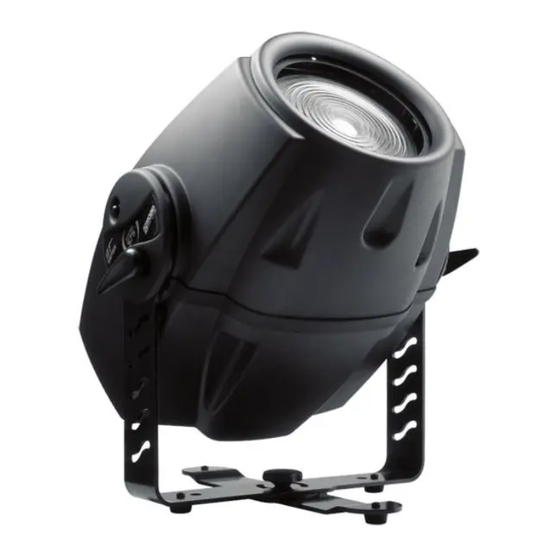
3.Description of the device 1 - Mounting bracket 4 - Front cover 2 - Rear cover 5 - Fresnel lens 3 - Adjusting screw Rear side 1 - Control board 2,3- Fans 4 - DMX output 5 - DMX input 6 - Lamp cover 7 - Fuse holder 8 - Power switch... -
Page 6: Installation
4.Installation 4.1Fitting/Exchanging the lamp DANGER ! Install the lamp with the device switched off only. Unplug from mains before ! Lamp cover: 3 fastening screws To insert the lamp MSR 575W/2 open the small cover at the rear of the projector by loosening the 3 screws „X, Y, Z” on the lamp cover. -
Page 7: Changing The Power Supply Settings
4.3. Changing the power supply settings Both the transformer and the ballast must be connected correctly for the local AC voltage and frequency. The wrong settings can cause poor performance or demage of the moving head.The factory settings are printed next to the power switch. -
Page 8: Rigging
4.4 Rigging DANGER TO LIFE! Please consider the respective national norms during the installation! The installation must only be carried out by an authorized dealer! The installation of the projector has to be built and constructed in a way that it can hold 10 times the weight for 1 hour without any harming deformation. - Page 9 Overhead installation. The mounting bracket provides 3 holes (a diameter of13mm) and 2 quarter-circle slots. To adjust the inclination-angle,loosen the 2 adjusting screws.Turn the projector to the desired angle and retighten the adjusting screws. For overhead use, always install a safety rope that can hold at least 10 times the weight of the fixture. Pull the safety rope through the mounting bracket and over the trussing system etc.
-
Page 10: Connection To The Mains
Removable stand: Measurements are in milimetres DANGER TO LIFE! Before taking into operation for the first time,the installation has to be approved by an expert! When installing fixtures side-by-side, avoid illuminating one fixture with another! 4.5 Connection to the mains Verify the power supply settings before applying power! If you wish to change the power supply settings,see the chapter Appendix. -
Page 11: Dmx 512 Connection, Master/Slave Connection
4.6 DMX 512 connection, master/slave connection Controller operation Master/slave operation The wires must not come into contact with each other, otherwise the fixtures will not work at all, or will not work properly. Only use a stereo shielded cable and 3-pin XLR-plugs and connectors in order to connect the controller with the fixture or one fixture with another. -
Page 12: Installation Of The Barn-Doors
4.7 Installation of the barn-doors You can install the barn-doors to better define the iluminated surface.The barn-doors are fixed with the 2 screws and may be turned in range 90°. Barn-doors are optional accessories. adjusting screws fastening screws 4.8 Changing the front lens The ColorMix 575 AT can use the 2 types of the front lenses: Fresnel lens - this lens is installed as a standard lens. -
Page 13: Dmx Protocol
5. DMX Protocol Mode 1 Mode 2 Value Function Type of control Channel Channel Power/Special functions 0-89 Reserved step To activate following functions, stop in DMX value for at least 3 s and shutter must be closed at least 3 s.("Shutter,Strobe" channel 12(10) must be at range:0-31 DMX). - Page 14 Mode 1 Mode 2 Value Function Type of control Channel Channel Colour wheel -fine positioning 0-255 Fine positioning proportional Cyan 0-255 Cyan (0-white,255-full cyan) proportional Magenta 0-255 Magenta (0-white,255 full magenta) proportional Yellow 0-255 Yellow (0-white,255-full yellow) proportional Speed of CMY and dimmer 0-255 Speed from max.
-
Page 15: Type Of Control
Mode 1 Mode 2 Value Function Type of control Channel Channel Zoom 0-255 Coarse zoom from min. to max. beam angle proportional Zoom fine 0-255 Fine movement of zoom proportional Shutter,strobe 0-31 Shutter closed step 32-63 No function (shutter open) step 64-95 Strobe-effect from slow to fast... -
Page 16: Controller Mode
6.Controller mode The fixtures are individually addressed on a data link and connected to the controller.The fixtures respond to the DMX signal from the controller. 6.1 DMX addressing The control panel on the front side of the base allows you to assign the DMX fixture address, which is defined as the first channel from which the COLORMIX 575 AT will respond to the controller. -
Page 17: Stand - Alone Mode
7. Stand - alone mode The fixtures on a data link are not connected to the controller but can execute pre-set programs which can be different for every fixture.To set the program to be played,see the "Stand-alone setting" ( menu "St.AL."). "Stand-alone operation"... -
Page 18: Control Menu Map
8.Control menu map Default settings=Bold print A001 dM.Ad. MA.SL. d.AbL MASt. SLA.1 SLA.9 SL.Ct. InFo Po.ti. totl rSEt La.ti. totl rSEt LA.St. totl rSEt tEMP. Cur.t. boAr. HEAd Hi.tE. boAr. HEAd rSEt boAr. HEAd DM.In. Func. (0-255) F.dim (0-255) VErS. IC1.r. - Page 19 En.Sn.(On,Off) dISP. turn (On,Off) d.On (On,Off) d.Int.(20...100) MI.SE(1...10...20) FAn.S. (Auto,HIGH) A.bLc. (On,Off) In.Po. Func. (0-255) F.dim (0-255) Stor. dF.SE. LAMP (On,Off) MAn.M. PrE.C. Colo. (Co. 01...Co.10) dimr (dim.0..dim.C.) MAn.C. Func.(0-255) F.dim (0-255) tESt St.AL. Audi.(On,Off) Auto tESt PrG.1 PrG.2 PrG.3 PLAY tESt PrG.1...
- Page 20 rESE. SPEC. LA.Ad. Zoom (0-255) CodE AdJ. Func. (0-255) F.CAL Colo (0-255) dimr (0-255) A.rES. uPd.M. (OFF,On)
-
Page 21: Functions Of The Control Panel
9. Functions of the control panel The control panel situated on the front panel of the base offers several features. You can simply set the DMX address,read the number of the lamp or unit hours, switch On and Off the lamp, run test, make a reset and also use many functions for setting fixture behaviour. Control elements on the control board: [MODE] button-leaves menu without saving changes. - Page 22 Cur.t. --- Current fixture temperatures. boAr.-Current temperature on the PCB in the fixture.Temperatures below 85°C are not critical. 82° C and more lead to the lamp being switched off and the fixture goes to "low power mode".Before switching the lamp on again (after 5 minutes),run a total fixture reset. HEAd-Current temperature of the fixture head inside.Temperatures below 75°C are not critical.
-
Page 23: Personality
9.4 Personality Use this menu to to modify ColorMix 575 AT operating behavior. DM.Pr. --- DMX preseting.Select this function to set desired effects assigning to the channels.Please refer to the chapter "DMX protocol" for detail description. LA.Pr. --- Lamp presetting.Select this menu to change the lamp "behaviour". LA.Au. -
Page 24: Manual Mode
9.6 Manual mode Select this menu to call up presetted positions of channel effects or direct control channel effects. PrE.C. --- Presetted effect control.Select this menu to call up presetted positions of the channel effects. Man.C. --- Manual effect control.Select this menu to control effects by control buttoms on the control board. Func. -
Page 25: Reset Functions
2. Press [UP] or [DOWN] to select the desired fixture ("MASt." - "SLA.9") and press [ENTER]-button. 3. Press [UP] or [DOWN] to select the desired program step ("St.01" - "St.99") and press [ENTER]-button. 4 Press [UP] or [DOWN] to select the desired item and press [ENTER]-button.Now you can edit by [UP] or [DOWN] buttons the DMX value (0-255) for selected item: P.End. -
Page 26: Low Power Mode
3.Unpack the program from the archive. Program file has name:DSU_name of corresponding fixture_SoftwareID.If the Robe fixture is produced in magnetic and electronic ballast version, the name of the DMX Software Uploader is the same for both versions.SoftwareID describes the versions of fixture software included in DMX Software Uploader. Higher number means later software versions. -
Page 27: Technical Specifications
M.b.Er. This messsage informs you that the main PCB does not communicate correctly with the control panel. F.t.Er. The message informs you that the fixture was overheating (occured if the ambient temperature is 40° C or more) and that the relay switched off the lamp. - Page 28 Optical System -High luminous-efficiency parabolic reflector -Standard Fresnel lens of diameter 200 mm - Motorized zoom 10°-26° with the standard Fresnel lens - 81° Beam angle with the optional wide-angle lens Beampath Fans Three axial fans Electronics Built-in microphone for music trigger Master/slave operation 3 freely programmable programs (99 steps each) Digital serial input DMX-512...
-
Page 29: Maintenance And Cleaning
Dimensions (mm): Optional accessories: Barn-doors......No. 99011064 Wide-angle lens.....No. 99011082 Flash cable RS232/DMX..No.13050624 13. Maintenance and cleaning The operator has to make sure that safety-relating and machine-technical installations are inspected by an expert after every four years in the course of an acceptance test. The operator has to make sure that safety-relating and machine-technical installations are inspected by a skilled person once a year. -
Page 30: Replacing The Fuse
Replacing the fuse If the lamp burns out, the fine-wire fuse of the device might fuse, too. Only replace the fuse by a fuse of same type and rating. Before replacing the fuse, unplug mains lead. Procedure: Step 1: Unscrew the fuseholder on the rear panel of the fixture with a fitting screwdriver from the housing (anti-clockwise). Step 2: Remove the old fuse from the fuseholder.
Need help?
Do you have a question about the Color mix 575 AT and is the answer not in the manual?
Questions and answers