
Related Manuals for Cebora SOUND MIG 2035/M Pulse


Summary of Contents for Cebora SOUND MIG 2035/M Pulse
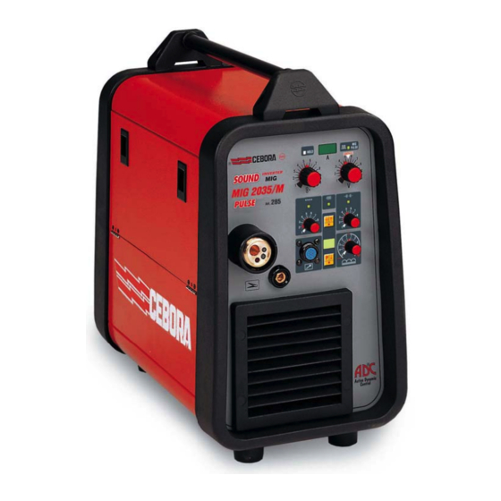
- Page 1 CEBORA S.p.A. SOUND MIG 2035/M Pulse POWER SOURCE art. 285 SERVICE MANUAL 3.302.161 24/03/2004...
-
Page 2: Table Of Contents
CEBORA S.p.A. CONTENTS - GENERAL INFORMATION.......................... 4 - Introduction..............................4 - General service policy..........................4 - Safety information............................4 - Electromagnetic compatibility........................4 - SYSTEM DESCRIPTION ..........................5 - Introduction..............................5 - Technical specifications..........................5 - Description of power source art. 285......................5 - Programming power source art. - Page 3 CEBORA S.p.A. - Error codes and alarm signals........................28 3.4.1 - 01 - Internal RAM error........................... 28 3.4.2 - 02 - EEPROM error..........................28 3.4.3 - 10 - Malfunction in the circuit to detect short-circuits at the output............28 3.4.4 - 14 - Microprocessor supply voltage error on control board (27).
-
Page 4: General Information
It is forbidden to attempt to repair damaged electronic boards or modules; replace them with original Cebora spare parts. 1.3 - Safety information. The safety notes provided in this manual are an integral part of those given in the Instruction Manual. -
Page 5: System Description
2 - SYSTEM DESCRIPTION 2.1 - Introduction. The SOUND MIG 2035/M Pulse is a system for MIG/MAG pulsed synergic, MIG/MAG non- pulsed synergic and MIG/MAG conventional welding. It is made up of an electronic power source (art. 285), and a set of accessories to adapt to various types of applications (see list in Sales Catalogue). - Page 6 CEBORA S.p.A. The diode group (56) is made up of two diodes connected to a shared cathode, and provides a positive output voltage with regard to the central socket of the transformer. Actually, each diode in the group is in turn made up of two diodes parallel connected together.
-
Page 7: Programming Power Source Art. 285 (Firmware Upgrade)
Programs and synergic curves are defined based on the experience earned by Cebora, and may be upgraded thanks to a programming system that uses the programming board (21) (connector J1) and a RS232 serial communication line. -
Page 8: Programs Tables
CEBORA S.p.A. 2.8 - Programs tables. 2.8.1 - Conventional non synergic programs (ver. H06). ∅ f ilo Materiale / Material Torch Torch Prg. N° Art. 1242 Art. 2003 ∅ w ire • • Ferro / Iron 0,6/0,8/(1) Argon / 18%CO •... -
Page 9: Pulsed Synergic Programs (Ver. P03)
CEBORA S.p.A. 2.8.3 - Pulsed synergic programs (ver. P03). ∅ f ilo Prg. Materiale / Material Torch Torch N° ∅ w ire Art. 1242 Art. 2003 • • Ferro / Iron Argon/CO • • Ferro / Iron Argon/CO • •... -
Page 10: Set-Up Mode Diagram
CEBORA S.p.A. 2.9 - Set-up mode diagram. OPERATING SET-UP MODE MODE NO WELD switch U=on START-UP O+R long = default SP (display G = speed). A (display G = current) (default). torch 2 Spot (led C=on, leds L–M=off). 1 Intermittent (led L=off, leds C–M=on). -
Page 11: Maintenance
CEBORA S.p.A. 3 - MAINTENANCE WARNINGS ANY INTERNAL INSPECTIONS OR REPAIRS MUST BE CARRIED OUT BY QUALIFIED PERSONNEL. BEFORE BEGINNING MAINTENANCE OPERATIONS, UNPLUG THE MACHINE FROM THE MAINS AND WAIT FOR THE INTERNAL CAPACITORS TO DISCHARGE (1 MINUTE) 3.1 - Periodic inspection, cleaning. -
Page 12: Power Source Operation
♦ After one second, display (G) indicates “Hxx” (H = conventional, synergic and non synergic programs tables; xx = the version of the programs (see tables 2.8.1 and 2.8.2)). Display (Q) indicates the version of the “firmware 285 Cebora”. ♦ After one second, display (G) indicates “Pxx” (P = pulsed synergic programs table;... - Page 13 CEBORA S.p.A. ♦ Display (G) indicates “dSp” if is the first time you enter in set-up mode, or the function code present last time you exit the set-up mode. ♦ By pressing the torch start button is possible to select all set-up functions available for the program selected, indicated by display Q, during operative mode (see diagram 2.9).
-
Page 14: Troubleshooting
CEBORA S.p.A. 3.3 - Troubleshooting. WARNINGS ANY INTERNAL INSPECTIONS OR REPAIRS MUST BE CARRIED OUT BY QUALIFIED PERSONNEL. BEFORE REMOVING THE PROTECTIVE GUARDS AND ACCESSING INTERNAL PARTS, DISCONNECT THE POWER SOURCE FROM THE MAINS AND WAIT FOR THE INTERNAL CAPACITORS TO DISCHARGE (1 MINUTE). - Page 15 CEBORA S.p.A. ♦ Check the wiring between J3 power supply board (25) and terminals TP3(+) and TP4(-) of power board (26). ♦ With the power source off, temporarily disconnect the power supply board (25) from the power board (26) and check the resistance between terminals 1 and 2 of J3 on power supply board (25).
-
Page 16: Power Source Powered, Control Panel On, Fan (24) Stopped
CEBORA S.p.A. 3.3.2 - Power source powered, control panel on, fan (24) stopped. FAN (24) TEST. Power board (26), connector J2, terminals 1(-) – 2(+) = +27 Vdc. Correct? ♦ Check the wiring between fan (24) and connector J2 on power board (26). -
Page 17: Power Source Powered, Display And Signals Does Not Indicate The Correct Values
= the version of the programs (see tables 2.8.1 and 2.8.2)). Display (Q) indicates the version of the “firmware 285 Cebora”. After one second, display (G) indicates “Pxx” (P = pulsed synergic program table; xx = the version of the programs (see table 2.8.3)). -
Page 18: The Start Button Produces No Effect
CEBORA S.p.A. 3.3.4 - The start button produces no effect. TORCH TYPE RECOGNITION TEST. Control board (27), connector J12, terminal 11 (or R85 left side) and connector Jl4 (-) = 0 Vdc with push-pull torch inserted (+5 Vdc with other torches). -
Page 19: Power Source Powered, No Gas Flows From The Torch
♦ Check for gas presence at the power supply fitting (T), and make sure that the pressure and flow in the intake line comply with the values specified for the SOUND MIG 2035/M Pulse. ♦ Make sure there are no occlusions in the gas hoses of the power source. - Page 20 CEBORA S.p.A. MOTOR SPEED REFERENCE SIGNAL TEST WITH TRADITIONAL TORCH. Control board (27), connector J12 terminal 24 (+) (or C79 left side) and connector J14 (-) = 0 / +5 Vdc adjustable with knob (B). Correct? ♦ Check the wiring between connectors J12 on control board (27) and J1 on panel board (41), and make sure the push-pull board (43) is properly mounted on panel board (41).
- Page 21 CEBORA S.p.A. ♦ Replace the wire feeder motor on the torch, or the entire torch. ♦ Replace the wire feeder motor (401). MOTOR SPEED REFERENCE SIGNAL TEST WITH PUSH-PULL TORCH. Control board (27), connector J12 terminal 4(+) (or C76 right side) and connector J14(-) = approximately 0 Vdc, with UP button on torch pressed;...
-
Page 22: In Open Circuit Operation, The Output Voltage Is Not Regular
CEBORA S.p.A. 3.3.7 - In open circuit operation, the output voltage is not regular. OPEN-CIRCUIT OUTPUT VOLTAGE TEST. Power source output terminals (F)(-) and (E)(+) = approximately +62 Vdc, with start button on the torch pressed. Correct? ♦ Correct operation. - Page 23 CEBORA S.p.A. CURRENT TO PRIMARY CIRCUIT OF TRANSFORMER (30) TEST. Control board (27), connector J4, terminals 3(+) – 4(-) = <0.1 Vdc, current to transformer (30) primary circuit, with start button pressed, and terminals of the secondary circuit disconnected from “anode” terminals of diodes (56).
-
Page 24: In Resistive Load Operation, The Output Voltage Is Not Regular
CEBORA S.p.A. 3.3.8 - In resistive load operation, the output voltage is not regular. NOTE For the following tests set continuous “Mode” (led L lit) and the working program n° 1, (see table 2.8.1). Turn the knobs (B) and (I) all the way clockwise (to maximum) and set the other knobs to their central position. - Page 25 CEBORA S.p.A. CURRENT ANALOG REFERENCE SIGNAL TEST. Control board (27), connector J12, terminal 23(+) (or C86 left side) and connector J14 (-) = 0 / +5 Vdc adjustable with knob (I). Correct? ♦ Check the wiring between connectors J12 on control board (27) and J1 on panel board (41), and make sure the push-pull board (43) is properly mounted on panel board (41).
-
Page 26: Arc Difficult To Strike, The Arc Goes Out Immediately After Lighting
CEBORA S.p.A. 3.3.9 - Arc difficult to strike, the arc goes out immediately after lighting. “Hot-Start” and “Soft Start” functions are adjustable by set-up menu (see diagram 2.9 and Instruction Manual). Also “Impedance” function, adjustable using knob (P), can assist welding start. -
Page 27: In Synergic Mode, The Welding Quality Is Not Satisfactory, The Wire Speed Is Not Suited To The Output Current
CEBORA S.p.A. 3.3.11 - In synergic mode, the welding quality is not satisfactory, the wire speed is not suited to the output current. NOTE The parameters entered into the synergic programs are drawn from experience, and thus some operators may find themselves working in ideal conditions, while others may need to make slight changes. -
Page 28: Error Codes And Alarm Signals
CEBORA S.p.A. 3.4 - Error codes and alarm signals. 3.4.1 - 01 - Internal RAM error. 3.4.2 - 02 - EEPROM error. Block due to software error. Replace the control board (27). 3.4.3 - 10 - Malfunction in the circuit to detect short-circuits at the output. -
Page 29: 30 - Incorrect Setting Of The Minimum Current Threshold On The Control Board (27)
CEBORA S.p.A. 3.4.7 - 30 - Incorrect setting of the minimum current threshold on the control board (27). MINIMUM THRESHOLD CURRENT SETTING. Control board (27), connector J4, terminal 4(-) and test-point TS4(+) = +360 mVdc, with power source powered. Correct? ♦... -
Page 30: 56 - Short-Circuit At The Output Lasts Too Long (Max. Allowable Duration = 1 Sec.)
CEBORA S.p.A. Check the wiring between connector J4 of control board (27) and current transducer (33), and the power wiring between the “cathode” terminals of diode group (56) and the central adapter for torch (38), and between the central transformer (30) socket, choke (29) and output terminal (F) of the power source. -
Page 31: 74 - Display (G) Indicates Th = Igbt High Temperature
CEBORA S.p.A. − Make sure that the thermostat mounted on the diode group (56) is properly assembled and functioning correctly; its contact must be closed at ambient temperature. − Replace the control board (27). 3.4.16 - 74 - Display (G) indicates tH = igbt high temperature. -
Page 32: Components List
CEBORA S.p.A. 4 - COMPONENTS LIST 4.1 - Power source art. 285 : see file ESP285.pdf enclosed at the end of the manual. 4.2 - Components table: see file ESP285.pdf enclosed at the end of the manual. 4.3 - Spare parts list. -
Page 33: Electrical Diagrams
CEBORA S.p.A. 5 - ELECTRICAL DIAGRAMS 5.1 - Power source art. 285 : see file SCHE285.pdf enclosed at the end of the manual. 5.2 - Waveforms. 5.2.1 - Transformer (30) secondary open-circuit voltage (par. 3.3.7). 5.2.2 - PWM1 and PWM2 signals for igbt command on power board (26) (par. 3.3.7). -
Page 34: Wire Feeder Motor (401) Voltage During Correct Braking (Par. 3.3.10)
CEBORA S.p.A. 5.2.3 - Wire feeder motor (401) voltage during correct braking (par. 3.3.10). 5.2.4 - Wire feeder motor (401) voltage during incorrect braking (par. 3.3.10). 5.2.5 - Mains voltage present signal (par. 3.4.17). 3.302.161 24/03/2004... -
Page 35: Filter Board (47) Code 5.602.164
CEBORA S.p.A. 5.3 - Filter board (47) code 5.602.164. 5.3.1 - Topographical drawing. 5.3.2 - Connector table. Connector Terminals Function TP5 - TP6 mains voltage input (230 Vac) 1 - 2 mains voltage output (230 Vac). 5.4 - Power supply (25) board code 5.602.163. -
Page 36: Power Board (26) Code 5.602.162
CEBORA S.p.A. 5.5 - Power board (26) code 5.602.162. 5.5.1 - Topographical drawing. 5.5.2 - Connector table. Connector Terminals Function 1 - 2 27 Vac input, for igbt temperature detection circuit insulated power supply. 1(-) - 2(+) fan (24) command output. -
Page 37: Driver-Igbt Board Code 5.600.757
CEBORA S.p.A. 5.6 - Driver-igbt board code 5.600.757. 5.6.1 - Topographical drawing. 5.6.2 - Connector table. Connector Terminals Function 1 - 2 command output for igbt1 gate. 1 - 2 command output for igbt2 gate. 1 - 2 PWM1 input. - Page 38 CEBORA S.p.A. 5.7.2 - Connector table. Conn. Terminals Function 1 - 2 start command input from traditional torch button. 1(+) - 2(-) output voltage signal input. 3(+) - 1(-) +5Vdc output for igbt temperature detection circuit power supply. 5 - 6 safety signals input (diode group overtemperature or wire coil cover open).
-
Page 39: Panel Board (41) Code 5.602.178
CEBORA S.p.A. 5.8 - Panel board (41) code 5.602.178. 5.8.1 - Topographical drawing. 5.8.2 - Connector table. Conn. Terminals Function. NU. (spool-gun torch selection output). push-pull motor speed regulator enable input. power source start signal output from push-pull torch start button. -
Page 40: Push-Pull Board (43) Code 5.602.171
CEBORA S.p.A. 5.9 - Push-pull board (43) code 5.602.171. 5.9.1 - Topographical drawing. 5.9.2 - Connector table. Conn. Terminals Function. push-pull torch motor (+) power output. push-pull torch UP/DOWN buttons “cursor” input. 3(-) - 10(+) +5 Vdc output for push-pull torch UP/DOWN buttons power supply. -
Page 41: Snubber Board (58) Code 5.602.166
CEBORA S.p.A. 5.10 - Snubber board (58) code 5.602.166. 5.10.1 - Topographical drawing. 5.10.2 - Connector table. Conn. Terminals Function. 1 - 2 wire coil cover open signal input. 1 - 2 wire coil cover open or diode group (56) overtemperature signals output.
Need help?
Do you have a question about the SOUND MIG 2035/M Pulse and is the answer not in the manual?
Questions and answers