
Related Manuals for Cebora TRI STAR MIG 1635/M


Summary of Contents for Cebora TRI STAR MIG 1635/M
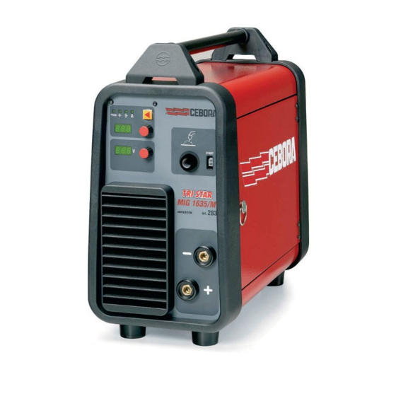
- Page 1 CEBORA S.p.A. TRI STAR MIG 1635/M POWER SOURCE art. 283 SERVICE MANUAL 3.302.233 22/09/2008...
-
Page 2: Table Of Contents
CEBORA S.p.A. CONTENTS - GENERAL INFORMATIONS ........................3 - Introduction..............................3 - General service policy..........................3 - Safety informations............................3 - Electromagnetic compatibility........................3 - SYSTEM DESCRIPTION ..........................4 - Introduction..............................4 - Technical specifications..........................4 - Description of power source art. 283......................4 - MAINTENANCE............................ -
Page 3: General Informations
It is forbidden to attempt to repair damaged electronic boards or modules; replace them with original Cebora spare parts. 1.3 - Safety informations. The safety notes provided in this manual are an integral part of those given in the Instruction Manual. -
Page 4: System Description
2 - SYSTEM DESCRIPTION 2.1 - Introduction. The TRI STAR MIG 1635/M is a multiprocess system for MIG/MAG, TIG-DC and MMA welding. It is made up of an electronic power source (art. 283) and a set of accessories to adapt to various types of applications (see list in the Sales Catalogue). - Page 5 CEBORA S.p.A. − two 3-digit displays to show output voltage, welding current, wire speed, values assignable to the selected parameters, material type, services functions and error codes. The welding current regulation is performed by the microprocessor on the control board (29), based on signals received from the power board (32), and parameters set via control panel.
-
Page 6: Maintenance
CEBORA S.p.A. 3 - MAINTENANCE WARNINGS ANY INTERNAL INSPECTIONS OR REPAIRS MUST BE CARRIED OUT BY QUALIFIED PERSONNEL. BEFORE BEGINNING MAINTENANCE OPERATIONS, UNPLUG THE MACHINE FROM THE MAINS AND WAIT FOR THE INTERNAL CAPACITORS TO DISCHARGE (2 MINUTES). 3.1 - Periodic inspection, cleaning. -
Page 7: Power Source Operation
♦ After three seconds, leds and displays lit (lamp test). Fans (27) working. ♦ After one second, display (M) indicates the Cebora article number (i.e.: “283”). ♦ After one second, display (M) indicates the version of the programs related to the synergic curves (i.e.: “H01”, H = synergic programs table, 01 = programs... -
Page 8: Mig Operation
CEBORA S.p.A. Correct? NO (see 3.3.3). 3.2.3 - MIG operation. NOTE On continuation it is illustrated the sequence of MIG process only, which involves all the circuits of the power source, and therefore is considerate sufficient for the purpose of this manual. -
Page 9: Troubleshooting
CEBORA S.p.A. 3.3 - Troubleshooting. WARNINGS ANY INTERNAL INSPECTIONS OR REPAIRS MUST BE CARRIED OUT BY QUALIFIED PERSONNEL. BEFORE REMOVING THE PROTECTIVE GUARDS AND ACCESSING INTERNAL PARTS, DISCONNECT THE POWER SOURCE FROM THE MAINS AND WAIT FOR THE INTERNAL CAPACITORS TO DISCHARGE (2 MINUTES). -
Page 10: Power Source Powered, Control Panel On, Fans (27) Stopped
♦ See Error codes and alarm signals, par. 3.4. INDICATORS TEST. Upon start-up, after the lamp-test, display (M) indicates the Cebora article number (i.e.: “283”). After one second, display (M) indicates the version of the programs related to synergic curves (i.e.: “H01”, H = synergic programs table (short), 01 = programs version);... -
Page 11: The Start Button Produces No Effect
CEBORA S.p.A. Correct? ♦ Check the wiring between J1 control board (29) and J1 power board (32). ♦ Check the wiring between J3 and J7 control board (29) and J4 power board (32). ♦ Carry out the CONTROL BOARD (29) POWER SUPPLY TEST, par. 3.3.1. -
Page 12: In Mig, The Wire Feeder Motor (31) Does Not Work
CEBORA S.p.A. ♦ Check the wiring between terminals J8 and J9 of power board (32) and solenoid valve (7). ♦ With the power source off, check the resistance on solenoid valve (7) terminals = 2500 ohm. If 0 ohm (short-circuit), replace solenoid valve (7) and power board (32). -
Page 13: In Open Circuit Operation, The Output Voltage Is Not Regular
CEBORA S.p.A. 3.3.7 - In open circuit operation, the output voltage is not regular. OPEN-CIRCUIT OUTPUT VOLTAGE TEST. Output terminal –(G) power source (-) and output terminal +(H) power source (+) = voltages per table: Process Voltage Condition +109 Vdc... -
Page 14: In Resistive Load Operation, The Output Voltage Is Not Regular
CEBORA S.p.A. 3.3.8 - In resistive load operation, the output voltage is not regular. OPEN-CIRCUIT OUTPUT VOLTAGE TEST. Output terminal –(G) power source (-) and output terminal +(H) power source (+) = voltages per table: Process Voltage Condition +109 Vdc... -
Page 15: In Mig, Arc Difficult To Strike, The Arc Goes Out Immediately After Lighting
CEBORA S.p.A. ♦ Replace power (32) and/or control (29) boards. ♦ Check connection between diode group heat sink on power board (32), inductor (28) and power source +(H) output terminal, and between TP9 on power board (32) and power source –(G) output terminal. -
Page 16: Error Codes And Alarm Signals
CEBORA S.p.A. 3.4 - Error codes and alarm signals. 3.4.1 - 02 - EEPROM error. Block due to software error. Replace the control board (29). 3.4.2 - 10 - Malfunction in the circuit to detect short-circuits at the output. Upon power source start-up this test checks the operating conditions by performing a brief test to generate the open-circuit output voltage. -
Page 17: 54 - Short-Circuit Between Torch And Workpiece Upon Start-Up
CEBORA S.p.A. 3.4.6 - 54 - Short-circuit between torch and workpiece upon start-up. Upon power source start-up this test checks the operating conditions by performing a brief test to generate the open-circuit output voltage. While this is taking place it is important that the torch not touch the workpiece or welding bench. -
Page 18: 61 - Mains Voltage Lower Than Minimum Limit
CEBORA S.p.A. 3.4.9 - 61 - Mains voltage lower than minimum limit. 3.4.10 - 62 - Mains voltage higher than maximum limit. The control board (29) verifies the mains voltage by means the +24 Vdc supply voltage check. If the mains voltage results suitable, the power source gets ready for the operation; if instead it is judged too low, the control commands the block for error 61, if too high commands the block for error 62. -
Page 19: Components List
CEBORA S.p.A. - COMPONENTS LIST 4.1 - Power source art. 283 : see file ESP283.pdf enclosed at the end of the manual. 4.2 - Components table: see file ESP283.pdf enclosed at the end of the manual. 4.3 - Spare parts list. -
Page 20: Electrical Diagrams
CEBORA S.p.A. 5 - ELECTRICAL DIAGRAMS 5.1 - Power source art. 283 : see file SCHE283.pdf enclosed at the end of the manual. 5.2 - Waveforms. 5.2.1 - Wire feeder motor (31) voltage during correct braking (par. 3.3.10). 5.2.2 - Wire feeder motor (31) voltage during incorrect braking (par. 3.3.10). -
Page 21: Power Board (32), Code 5.602.280/B
CEBORA S.p.A. 5.3 - Power board (32), code 5.602.280/B. 5.3.1 - Topographical drawing. 5.3.2 - Connector table. Conn. Terminals Function 1 - 2 RL1 rele command input (precharge 1). RL2 rele command input (precharge 2). RL3 rele command input (solenoid valve). -
Page 22: Control Board (29), Code 5.602.269/A
CEBORA S.p.A. 5.4 - Control board (29), code 5.602.269/A. 5.4.1 - Topographical drawing. 5.4.2 - Connector table. Conn. Terminals Function 1 - 2 RL1 rele command output (precharge 1). RL2 rele command output (precharge 2). RL3 rele command output (solenoid valve). - Page 23 Art. 283...
- Page 24 Art. 283 pos DESCRIZIONE DESCRIPTION LATERALE FISSO FIXED SIDE PANEL SUPPORTO MANICO HANDLE SUPPORT MANICO HANDLE COPERCHIO COVER CORNICE FRAME PANNELLO POSTERIORE BACK PANEL ELETTROVALVOLA SOLENOID VALVE COPERTURA COVER INTERRUTTORE SWITCH PRESSACAVO STRAIN RELIEF CAVO RETE POWER CORD PANNELLO ALETTATO FINNED PANEL CERNIERA HINGE...
Need help?
Do you have a question about the TRI STAR MIG 1635/M and is the answer not in the manual?
Questions and answers