Advertisement
Quick Links
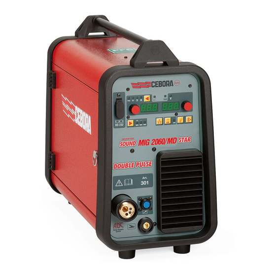
INSTRUcTION MANUAL fOR WIRE WELDINg MAcHINE
IMPORTANT:
BEFoRE sTARTINg THE EQUIpmENT,
REAd THE CoNTENTs oF THIs mANUAL, WHICH mUsT
BE sToREd IN A pLACE FAmILIAR To ALL UsERs FoR
THE ENTIRE opERATIvE LIFE-spAN oF THE mACHINE.
THIs EQUIpmENT mUsT BE UsEd soLELY FoR WELd-
INg opERATIoNs.
1 SAfETY PREcAUTIONS
WELdINg ANd ARC CUTTINg CAN BE
HARmFUL To YoURsELF ANd oTHERs.
The user must therefore be educated
against the hazards, summarized below, deriving from weld-
ing operations. For more detailed information, order the
manual code 3.300.758
NoIsE
This machine does not directly produce noise
exceeding 80dB. The plasma cutting/welding proce-
dure may produce noise levels beyond said limit;
users must therefore implement all precautions required by
law.
ELECTRIC ANd mAgNETIC FIELds - may be dangerous.
· Electric current following through any con-
ductor causes localized Electric and magnetic
Fields (EmF). Welding/cutting current creates
EmF fields around cables and power sources.
· The magnetic fields created by high currents
may affect the operation of pacemakers. Wearers of vital
electronic equipment (pacemakers) shall consult their physi-
cian before beginning any arc welding, cutting, gouging or
spot welding operations.
· Exposure to EmF fields in welding/cutting may have other
health effects which are now not known.
· All operators should use the followingprocedures in
order to minimize exposure to EmF fields from the weld-
ing/cutting circuit:
- Route the electrode and work cables together - secure
them with tape when possible.
- Never coil the electrode/torch lead around your body.
- do not place your body between the electrode/torch
lead and work cables. If the electrode/torch lead cable
is
on your right side, the work cable should also be on
your
right side.
- Connect the work cable to the workpiece as close as
possible to the area being welded/cut.
- do not work next to welding/cutting power source.
EXpLosIoNs
· do not weld in the vicinity of containers under pres-
sure, or in the presence of explosive dust, gases or
fumes. · All cylinders and pressure regulators used in
welding operations should be handled with care.
ELECTRomAgNETIC CompATIBILITY
This machine is manufactured in compliance with the
instructions contained in the standard IEC 60974-10 (CL. A),
and must be used solely for professional purposes in an
industrial environment. There may be potential difficul-
ties in ensuring electromagnetic compatibility in non-
industrial environments.
10
H.F FREQUENCY
• High frequency (H.F.) can interfere with
radio navigation, safety services, computers,
and communications equipment.
• Have only qualified persons familiar with
electronic equipment perform this installation.
• The user is responsible for having a quali-
fied electrician promptly correct any interference problem
resulting from the installation.
• If notified by the FCC about interference, stop using the
equipment at once.
• Have the installation regularly checked and maintained.
• Keep high-frequency source doors and panels tightly shut,
keep spark gaps at correct setting, and use grounding and
shielding to minimize the possibility of interference.
dIsposAL oF ELECTRICAL ANd ELECTRoNIC
EQUIpmENT
do not dispose of electrical equipment together
with normal waste!In observance of European
directive 2002/96/EC on Waste Electrical and Electronic
Equipment and its implementation in accordance with
national law, electrical equipment that has reached the
end of its life must be collected separately and returned
to an environmentally compatible recycling facility. As the
owner of the equipment, you should get information on
approved collection systems from our local representa-
tive. By applying this European directive you will improve
the environment and human health!
IN CAsE oF mALFUNCTIoNs, REQUEsT AssIsTANCE
FRom QUALIFIEd pERsoNNEL.
1.1 WARNINg LABEL
The following numbered text corresponds to the label
numbered boxes.
B. drive rolls can injure fingers.
C. Welding wire and drive parts are at welding voltage
during operation — keep hands and metal objects
away.
1
Electric shock from welding electrode or wiring can
kill.
1.1 Wear dry insulating gloves. do not touch electrode
with bare hand. do not wear wet or damaged gloves.
1.2 protect yourself from electric shock by insulating
yourself from work and ground.
1.3 disconnect input plug or power before working on
machine.
2
Breathing welding fumes can be hazardous to your
health.
2.1 Keep your head out of fumes.
2.2 Use forced ventilation or local exhaust to remove
fumes.
2.3 Use ventilating fan to remove fumes.
3
Welding sparks can cause explosion or fire.
3.1 Keep flammable materials away from welding.
3.2 Welding sparks can cause fires. Have a fire extingui-
sher nearby and have a watchperson ready to use it.
3.3 do not weld on drums or any closed containers.
4
Arc rays can burn eyes and injure skin.
10
Advertisement

Related Manuals for Cebora MIG 2060 MD


Summary of Contents for Cebora MIG 2060 MD
-
Page 1: Instruction Manual For Wire Welding Machine
INSTRUcTION MANUAL fOR WIRE WELDINg MAcHINE IMPORTANT: BEFoRE sTARTINg THE EQUIpmENT, H.F FREQUENCY REAd THE CoNTENTs oF THIs mANUAL, WHICH mUsT • High frequency (H.F.) can interfere with BE sToREd IN A pLACE FAmILIAR To ALL UsERs FoR radio navigation, safety services, computers, THE ENTIRE opERATIvE LIFE-spAN oF THE mACHINE. - Page 2 4.1 Wear hat and safety glasses. Use ear protection and button shirt collar. Use welding helmet with correct shade of filter. Wear complete body protection. Become trained and read the instructions before working on the machine or welding. do not remove or paint over (cover) label. 2 gENERAL DEScRIPTIONS 2.1 SPEcIfIcATIONS The sound 2060/md star double pulse is an equipment...
- Page 3 secondary open-circuit voltage. bers appear on the display, contact technical service. duty cycle percentage. The duty cycle 2.3.2 Overload cut-out expresses the percentage of 10 minutes during which the welding machine may run This machine is protected by a thermostat, which pre- at a certain current without overheating.
- Page 4 LED Ac Wire speed. open. When the machine is in the error mode it displays Err. Indicates that the display AL shows the wire speed in Display AM. welding. displays by the number: in synergic mIg the arc length LED AD current. and in conventional mIg the welding voltage.
- Page 5 shows that you are inside the saving menu of the saved off/oN activates and disables the spot function. The spot welding time tSP is set from 0.3 to 5 seconds. working points. The interval between two spots tIN is set from 0,3 to 5 Selection key AY.
- Page 6 The adjustment may range from -9.9 to +9,9. Zero is the 11- PP (push-pull). By using push-pull torch Art. 2003 function PPf (push number set by the manufacturer:if the number is negative, the impedance decreases and the arc becomes harder; if pull Force) is enabled which adjusts the drive torque of increased, it becomes softer.
- Page 7 AI. and AN respectively. Fig. 4 8 AccESSORIES 8.1 MIg WELDINg TORcH ART. 1242 Air-cooled CEBoRA mIg welding torch 280 A 3,5. 6.1 PLAcEMENT 8.2 PUSH-PULL UP/DOWN WELDINg TORcH, airr The weight of the welding machine is approximately 22 cooled, ART.
- Page 9 cODIfIcA cOLORI cABLAggIO ELETTRIcO - WIRINg DIAgRAM cOLOUR cODE Q BIANCO-ROSSO WHITE-RED A NERO BLACK K MARRONE BROWN R GRIGIO-ROSSO GREY-RED B ROSSO J ARANCIO ORANGE S BIANCO-BLU WHITE-BLUE C GRIGIO GREY I ROSA PINK T NERO-BLU BLACK-BLUE L ROSA-NERO PINK-BLACK D BIANCO WHITE...
- Page 10 pos DEScRiZiONE DEScRiPTiON pos DEScRiZiONE DEScRiPTiON MANICO HANDLE CONVOGLIATORE ARIA AIR CONVEYOR SUPPORTO MANICO HANDLE SUPPORT TRASDUTTORE TRANSDUCER COPERCHIO COVER IMPEDENZA SECONDARIO SECONDARY IMPEDANCE CHIUSURA CLOSING TRASFORMATORE DI POTENZA POWER TRANSFORMER ROSETTA WASHER RINFORZO CONVOGLIATORE REINFORCEMENT CONVEYOR LATERALE MOBILE HINGED SIDE PANEL PIEDE IN GOMMA RUBBER FOOT CERNIERA...
- Page 12 DEScRiZiONE DEScRiPTiON MOTORIDUTTORE COMPLET0 MOTOR COMPLETE ISOLAMENTO INSULATION ENCODER ENCODER BLOCCAGGIO GRADUATO ADJUSTMENT KNOB GUIDAFILO WIRE DRIVE PIPE ASSY GRUPPO GUIDAFILO WIRE GUIDE GROUP ISOLANTE COMPLETO INSULATION ASSY PROTEZIONE MOTORIDUTTORE GEAR MOTOR PROTECTION GRUPPO GUIDAFILO COMPLETO WIRE GUIDE GROUP COMPLETE RULLO TRAINAFILO (0,6/0,8) ROLLER WIRE(0,6/0,8) POMELLO...
- Page 13 MOTORiDUTTORE cOMPLETO wiRE fEED MOTOR cOMPLETE...
- Page 14 S.p.A - via Andrea Costa, 24 - 40057 Cadriano di granarolo - BoLogNA - Italy Tel. +39.051.765.000 - Fax. +39.051.765.222 www.cebora.it - e-mail: cebora@cebora.it...
Need help?
Do you have a question about the MIG 2060 MD and is the answer not in the manual?
Questions and answers