Table of Contents
Advertisement
Quick Links
Advertisement
Table of Contents

Related Manuals for ITS Telecom CGW-T4


Summary of Contents for ITS Telecom CGW-T4
- Page 1 CGW-T4 Installation and Operation Guide Release 1.02 March 2009...
- Page 2 CGW-T4 Installation and Programming Manual CGW-T4 Installation and Programming Manual Pre-Release 1, Revision 1, September 2008 (Preliminary version) - 1 -...
- Page 3 CGW-T4 Installation and Programming Manual NOTICE This manual describes the CGW-T4 Analog GSM/CDMA Cellular Gateway. Additional copies of this manual may be obtained from ITS. No part of this document may be reproduced or transmitted in any form, by any means (electronic, photocopying, recording, or otherwise) without the prior written permission of ITS.
-
Page 4: Table Of Contents
Installation ................................ 7 SIM Card Insertion into the Unit (GSM channels only) ......7 CGW-T4 Installation..................8 LCD Status Indicators and Diagnostics ....................... 9 CGW-T4 LCD Status Indicators and Diagnostics ........9 DTMF Programming ............................11 DTMF Programming Commands .............12 Technical Data ..............................15 CGW-T4 Channels for GSM Network .............15... -
Page 5: Introduction
PBX trunk interfaces, attach the antennas and power supply, and your CGW-T4 can immediately start saving money for you. The unit has an LCD display for each channel, which shows the GSM/CDMA operator’s name, the signal strength and other useful call progress information. -
Page 6: Main Features
CGW-T4 Installation and Programming Manual 1.1 Main Features The following is a list of Main Features of the CGW-T4 GSM/CDMA gateway: Integrated dual-band GSM module (900/1800, 850/1900 MHz) or Integrated dual- band CDMA module (800/1900 MHz) 4 Built-in LCD’s for each cellular channel •... -
Page 7: Physical Description
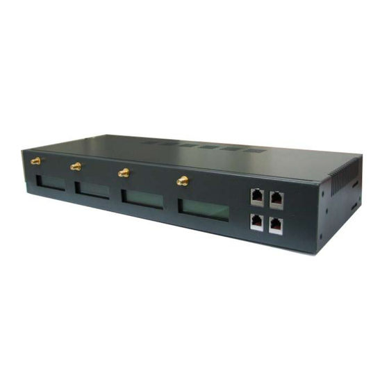
CGW-T4 Installation and Programming Manual 2 Physical Description The physical features of the CGW-T4 are detailed in Figure 2. Figure 2. CGW-T4 Physical Description CGW-T4 front panel includes : FXS analog telephone interfaces RJ-11 sockets LCD displays for each cellular channel Cellular Channel’s SMA antennas... -
Page 8: Pre-Installation
3 Pre-Installation 3.1 GSM Cellular Channels The CGW-T4 unit contains a GSM engines. It therefore needs a SIM cards from the local GSM network providers. Its registration to the GSM operator is similar to the registration of a mobile GSM phone. -
Page 9: Installation
4.1 SIM Card Insertion into the Unit (GSM channels only) CAUTION To avoid damage to the CGW-T4 unit, disconnect the 9V adapter from the electric power outlet. The physical description of the unit can be used as guideline for the following steps: SIM card’s holders can be found on the right and left lateral surfaces (See Figure 3 ). -
Page 10: Cgw-T4 Installation
4.2 CGW-T4 Installation To install the CGW-T4 unit, perform the steps as follows: Mount the CGW-T4 unit in the 19-inch rack or on the wall by using installation brackets or place the unit on the horizontal surface. Connect the antennas into the ‘Ant.’ SMA connectors on the front panel of the CGW-4 unit. -
Page 11: Lcd Status Indicators And Diagnostics
5 LCD Status Indicators and Diagnostics 5.1 CGW-T4 LCD Status Indicators and Diagnostics The CGW-T4 Gateway can be connected to the analog trunks interface of the PBX or directly to the analog home phone. At power-up of the CGW-T4 unit, the information on the LCD will provide the first diagnostics. - Page 12 CGW-T4 Installation and Programming Manual LCD Message Description Action CGW-T4 receives incorrect Failed operation information from the Try again. mobile network. Power off and on the unit. If error is repeated, Engine Problem GSM/CDMA engine problem. the unit is faulty.
-
Page 13: Dtmf Programming
Pick up the handset, hear the dialtone and Dial *900 then enter the password (1234 by default). Use the commands in the following table for programming. NOTE The CGW-T4 cellular channel will not answer incoming calls when programming mode is active. Exit from the programming mode by *900 (Recommended) or hanging up the telephone. -
Page 14: Dtmf Programming Commands
CGW-T4 Installation and Programming Manual 6.1 DTMF Programming Commands Operation Command Default Enter the Programming mode *900 + XXXX 1234 where: XXXX = Password (1234 default) Exit the Programming mode *900 Maximum number of digits to be *300 + XX... - Page 15 CGW-T4 Installation and Programming Manual Operation Command Default DTMF support option (CDMA *350 + X, where: only) X = 1 enabled; X = 0 disabled Verification of the Telephone *360 Number Display the SIM telephone number on the LCD for 5 seconds when in programming mode.
- Page 16 *550 + X 1 – Basic version. Restriction) where: In some types the X = 0, off The CGW-T4 can be restricted to default is 0 – X = 1, on show its SIM telephone number. contact your local distributor.
-
Page 17: Technical Data
CGW-T4 Installation and Programming Manual 7 Technical Data 7.1 CGW-T4 Channels for GSM Network Model CGW-T4 GSM Gateway GSM Network Type GSM Phase II GSM Module Integrated dual-band (900/1800, 850/1900 MHz) SIM card Plug-in, 3V, small Transmission Power Max. 2W / 900MHz Max. 2W / 850MHz Max. -
Page 18: Cgw-T4 Channels For Cdma Network
CGW-T4 Installation and Programming Manual Dimensions L x W x H 433 x 174 x 64 mm / 17,0 x 6,85 x 2,51 inch Weight 2,8 kg 7.2 CGW-T4 Channels for CDMA Network Model CGW-T4 CDMA Channel CDMA Network CDMA, CDMA 1X... - Page 19 CGW-T4 Installation and Programming Manual - 17 -...
Need help?
Do you have a question about the CGW-T4 and is the answer not in the manual?
Questions and answers