Table of Contents
Advertisement
Quick Links
Room Air Conditioners
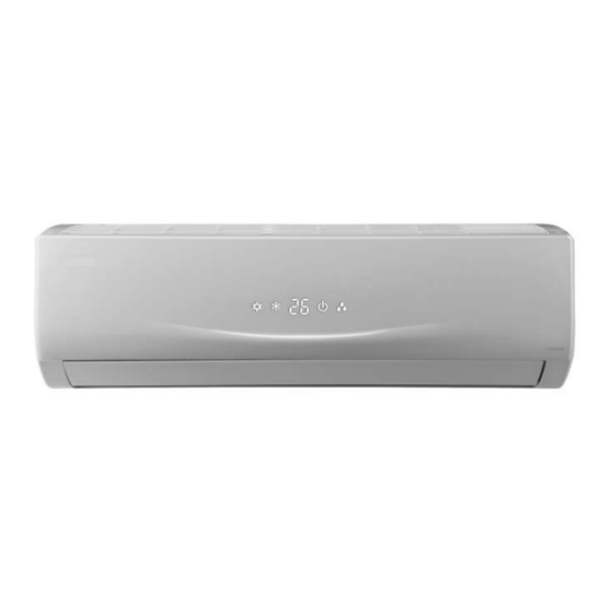
Z Series Inverter Range Split Type
DC Inverter
ECO1850SD
Register your air conditioner
Model information can be found on the CE
label.
Please register your product online at
www.ecoair.org. For your future
convenience, record the model information
below.
____________________________________
MODEL NUMBER
____________________________________
SERIAL NUMBER
____________________________________
PURCHASE DATE
Advertisement
Table of Contents

Subscribe to Our Youtube Channel
Related Manuals for Ecoair ECO1850SD


Summary of Contents for Ecoair ECO1850SD
- Page 1 Z Series Inverter Range Split Type DC Inverter ECO1850SD Register your air conditioner Model information can be found on the CE label. Please register your product online at www.ecoair.org. For your future convenience, record the model information below. ____________________________________ MODEL NUMBER ____________________________________ SERIAL NUMBER...
- Page 2 What’s in the box 1 x Z Series Indoor Unit 1 x Z Series Outdoor Unit 1 x Remote Control 1 x Drain Hose 1 x User Manual 1 x Hole Cover Plate 1 x Drain Joint 4 x Wall Plugs and Screws. 1 set of Copper Pipes This appliance can be used by minors from 8 years and above and persons with reduced physical, sensory or mental capabilities or lack of experience and knowledge if they have been given supervision...
-
Page 3: Table Of Contents
Content BS Plug Wiring ...................... 1 Operation Notices Precautions ......................2 Part Names ......................3 Screen Operation GuideScreen Operation Guide Buttons on the remote control ................Introduction to buttons on the display screen ............Introduction for buttons on the remote control ............Function introduction for combination buttons ............ -
Page 4: Bs Plug Wiring
BS Plug Wiring Wiring Instructions: Should it be necessary to change the plug please note the wires in the mains lead are coloured in accordance with the following code: BLUE - NEUTRAL BROWN – LIVE GREEN AND YELLOW - EARTH As the colours of the wires in the mains lead of this appliance may not correspond with the coloured markings identifying the terminals in your plug, proceed as follows:... -
Page 5: Precautions
PRECAUTIONS Working temperature range B/WB( 32/23 40/- 27/- 24/18... -
Page 6: Part Names
Part Names Indoor Unit air inlet panel aux.button horizontal louvre cooling power receiver air outlet indicator indicator window display H O U R ONOFF ON OF F heating temp. drying indicator indicator indicator X-FAN TURBO (Display content or position may be different from the remote control above graphics, please refer to actual products) Outdoor Unit... -
Page 7: Buttons On The Remote Control
Buttons on remote control ON/OFF button - button + button MODE button H O U R ONOFF FAN button SWING button I FEEL button (optional) button (optional) SLEEP button TEMP button TIMER-ON button CLOCK button TIMER-OFF button TURBO button LIGHT button X-FAN button (optional) -
Page 8: Introduction For Buttons On The Remote Control
Introduction to buttons on remote control Note: After turning on the power, the air conditioner will give out a sound. Operation indictor " " is ON (red indicator). After that, you can operate the air conditioner by using remote control. Under on status, pressing the button on the remote controller, the signal icon "... - Page 9 Introduction to buttons on remote control SWING button Press this button to set the up & down swing angle, which circularly changes as below: This remote control is universal. If any command , is sent out, the unit will carry out the command as indicates the guide louvre swings as: I FEEL button...
- Page 10 Introduction to buttons on remote control Note: an selected for some models. When indoor unit receives " " signal, it displays indoor set temperature. TIMER-ON button Press this button to initiate the auto-ON timer. To cancel the auto-timer program, simply press this button again.
-
Page 11: Function Introduction For Combination Buttons
Function introduction for combination buttons Combination of "+" and "-" buttons: About lock Press "+" and "-" buttons simultaneously to lock or unlock the keypad. If the remote controler is locked, is displayed. In this case, pressing any button, blinks three times. Combination of "MODE"... -
Page 12: Operation
Operation guide After connecting the power, press "ON/OFF" button on remote controller to turn on the air conditioner. Press "MODE" button to select your required mode: AUTO, COOL, DRY, FAN, HEAT. Press "+" or "-" button to set your required temperature. (Temperature can’t be adjusted under auto mode). -
Page 13: Emergency Operation
Emergency operation If remote control is lost or damaged, please use auxiliary button to turn on or turn off the air conditioner. The operation in details are as below: air conditioner. When the air conditioner is turned on, it will operate under auto mode. -
Page 14: Cleaning And Maintenance
(below 45 ) to clean it, and then air dry in the shade to avoid deformation . Note : Its good to change filter every 2 years. To purchase new filter contact EcoAir or your dealer. picture. panel cover tightly. Note:... - Page 15 Cleaning and Maintenance Checking before use-season 1. Check whether air inlets and air outlets are blocked. 2. Check whether isolator, plug and socket are in good condition. 4. Check whether mounting bracket for outdoor unit is damaged or corroded. If yes, please contact dealer. 5.
-
Page 16: Malfunction Analysis
Malfunction analysis General phenomenon analysis Please check below items before asking for maintenance. If the malfunction still air conditioning engineer. Phenomenon Check items Solution affected (such as static electricity, stable voltage)? then turn on the unit again. within the signal receiving range? Indoor unit can’t receive... - Page 17 Malfunction analysis...
- Page 18 Malfunction analysis Phenomenon Check items Solution ’s odour source, Odours are such as furniture and cigarette, emitted etc. ’s interference, r, turn on Air conditioner such as thunder, wireless power, and then turn on the operates abnormally devices, etc. unit again. suddenly Outdoor ating mode, it may generate...
- Page 19 Malfunction analysis Error Code Warning...
-
Page 20: Installation Dimension Diagram
Installation dimension diagram Space to the wall At least 15cm At least 15cm Space to the wall Drainage pipe... -
Page 21: Tools For Installation
Tools for installation 1 Level 2 Screw driver 3 Impact drill 4 Drill head 5 Pipe expander 6 Torque wrench 7 Open-end wrench 8 Pipe cutter 9 Leakage detector 10 Vacuum pump 11 Pressure meter 12 Universal meter 13 Inner hexagon spanner 14 Measuring tape Note: Selection of installation location... -
Page 22: Requirements For Electric Connection
Requirements for electrical connection Safety precaution 1. Follow electricity Safety Regulations when installing the unit. isolation switch. 3. Make sure the power supply matches with the requirement of the air conditioner. Unstable power supply or incorrect wiring will lead to malfunction and void warranty. Please install correct power supply cables before using the air conditioner. -
Page 23: Installation Instalation Of Indoor Unit
Installation of indoor unit Step one: choosing installation location rm it with the client. Step two: install wall-mounting frame 1. Hang the wall-mounting frame on the wall; adjust it in horizontal position with a a spirit raw plug push plastic raw plugs in the holes. 3. - Page 24 Installation of indoor unit Indoor outdoor Note: opening the hole. 5-10 and should be bought locally. Step four: outlet pipe 1. The pipe can be led out in the 2. When select leading out the pipe direction of right, rear right, left or from left or right, please cut off the rear left.
- Page 25 Installation of indoor unit Hex nut diameter Tightening torque (N . m) open-end wrench 30~40 union nut pipe torque wrench indoor pipe 4. Wrap the indoor pipe and joint of con- nection pipe with insulating pipe, and then wrap it with tape. insulating pipe Step six: install drain hose 1.
- Page 26 Installation of indoor unit 2. Make the power connection wire go cable-cross through the cable-cross hole at the back hole of indoor unit and then pull it out from the front side. power connection wire 3. Remove the wire clip; connect the power connection wire to the wiring terminal according to the colour;...
- Page 27 Installation of indoor unit Step eight: wrap up pipes 1. Wrap up the connection pipe, power drain hose connection pipe band cord and drain hose with the band. indoor and outdoor power cord indoor unit pipe indoor power cord liquid pipe 3.
-
Page 28: Installation Of Outdoor Unit
Installation of outdoor unit (select it according to the actual installation situation) 1. Select installation location according to the house structure. 2. Fix the bracket of outdoor unit on the selected location with expansion bolts. Note: installing the outdoor unit. Make sure the bracket can withstand at least four times the unit weight. - Page 29 Installation of outdoor unit Step four: connect indoor and outdoor pipes 1. Remove the screw on the right han- 3. Pretightening the union nut with dle of outdoor unit and then remove hand. the handle. pipe joint screw handle union nut 2.
- Page 30 Installation of outdoor unit 2. Fix the power connection wire and signal control wire with wire clip (only for cooling and heating unit). Note: After tightening the screw, pull the power cord slightly to check if it is firm. Step six: tidy the pipes 1.
-
Page 31: Vaccum Pumping
Vacuum pumping Use vacuum pump 1. Remove the valve caps on the liquid valve and gas liquid valve piezometer valve and the dust cap to the gas valve service charging vent. refrigerant charging 2. Connect the charging hose valve cap vent of piezometer to the refri- gerant charging vent of gas... -
Page 32: Post Installation Checklist
Post Installation Checklist Items to be checked Possible malfunction The unit may drop, shake or emit noise. Have you done the refrigerant leakage test? (heating) capacity. It may cause condensation and water dripping. It may cause condensation and water Is water drained well? dripping. -
Page 33: Configuration Of Connection Pipe
Configuration of connection pipe 1. Standard length of connection pipe x. high difference. Max length Max length Cooling Max height Cooling Max height of connec- of connec- capacity difference capacity difference tion pipe tion pipe The additional refrigerant oil and refrigerant charging required after extending connection pipes. - Page 34 Configuration of connection pipe Additional refrigerant charging amount for R22, R407C, R410A and R134a Diameter of connection pipe Outdoor unit throttle Liquid pipe(mm) Gas pipe(mm) Cooling only(g/m) Cooling and heating(g/m)
-
Page 35: Pipe Expanding Method
Pipe expanding method Note: Improper pipe expanding is the main cause of refrigerant leakage. Please expand the pipe according to the following steps: A:Cut the pipe ,clean edges and make E: Expand the port sure there is no debris in the copper tubes hard the distance of indoor unit and... - Page 36 SERVICE AND WARRANTY ONE (1) YEAR LIMITED WARRANTY Save This Warranty Information Eco Air guarantees this product free from defects in materials and workmanship for a period of one (1) year from the date of purchase. Coverage is valid only with proof of purchase. Faults arising from a faulty installation is specifically excluded.
Need help?
Do you have a question about the ECO1850SD and is the answer not in the manual?
Questions and answers