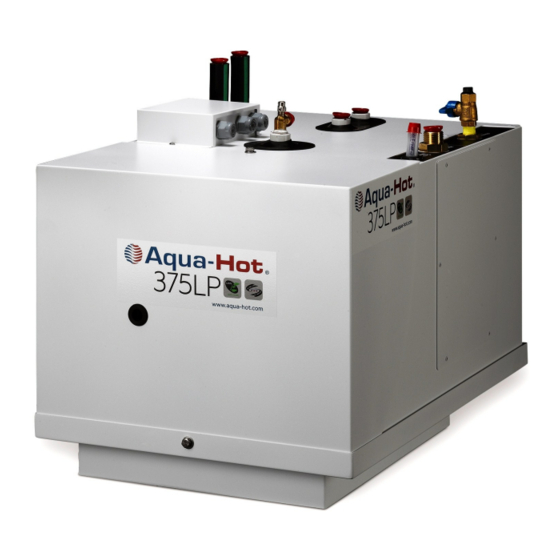
Aqua-Hot 375LP Installation Manual
Hydronic (water based) heating system, and a tank-less hot water system
Hide thumbs
Also See for Aqua-Hot 375LP:
- Service manual (92 pages) ,
- Owner's manual (24 pages) ,
- Installation manual (56 pages)
Table of Contents
Advertisement
Quick Links
WARNING: If the information in these instructions is
not followed exactly, a fire or explosion may result
causing property damage, personal injury, or death.
— Do not store or use gasoline or other flammable va-
pors and liquids in the vicinity of this or any other
appliance.
— WHAT TO DO IF YOU SMELL GAS
• Evacuate all persons from the vehicle.
• Shut off the gas supply at the gas container or
source.
• Do not touch any electrical switch or use any
phone or radio in the vehicle.
• Do not start the vehicle's engine or electric
generator.
• Contact the nearest gas supplier or qualified
service technician for repairs.
• If you cannot reach a gas supplier or qualified
service technician, contact the nearest fire
department.
• Do not turn on the gas supply until the gas leak(s)
has been repaired.
— Installation and service must be performed by a quali-
fied installer, service agency, or the gas supplier.
AHE-375-P02 INSTALLATION MANUAL
AVERTISSEMENT. Assurez-vous de bien suivre les
instructions données dans cette notice pour réduire au
minimum le risque d'incendie ou d'explosion ou pour
éviter tout dommage matériel, toute blessure ou la
mort.
— Ne pas entreposer ni utiliser d'essence ou ni d'autres
vapeurs ou liquides inflammables à proximité de cet
appareil ou de tout autre appareil.
— QUE FAIRE SI VOUS SENTEZ UNE ODEUR DE GAZ :
• Évacuez le véhicule.
• Coupez l'alimentation en gaz au réservoir ou à la
source.
• Ne touchez à aucun interrupteur ; ne pas vous
servir du téléphone ou de la radio du véhicule.
• Ne pas démarrer le moteur du véhicule ni aucune
génératrice électrique.
• Appelez le fournisseur de gaz le plus proche ou un
technicien qualifié.
• Si vous ne pouvez rejoindre ni un fournisseur ni un
technicien qualifié, appelez le service des
incendies le plus proche.
• Ne pas rétablir l'alimentation en gaz tant que la
fuite n'a pas été réparée.
— L'installation et l'entretien doivent être assurés par
un installateur ou un service d'entretien qualifié ou
par le fournisseur de gaz.
© 2010 Aqua-Hot Heating Systems Inc.
Advertisement
Table of Contents

Related Manuals for Aqua-Hot Aqua-Hot 375LP


Summary of Contents for Aqua-Hot Aqua-Hot 375LP
- Page 1 AVERTISSEMENT. Assurez-vous de bien suivre les WARNING: If the information in these instructions is instructions données dans cette notice pour réduire au not followed exactly, a fire or explosion may result minimum le risque d’incendie ou d’explosion ou pour causing property damage, personal injury, or death. éviter tout dommage matériel, toute blessure ou la mort.
-
Page 3: Table Of Contents
ABLE OF ONTENTS Aqua-Hot 375-LP Installation Manual Introduction ............................5 Section 1: Aqua-Hot Hydronic Heating System Technical Information .......................... 6 Section 2: Aqua-Hot Installation Installing the Mounting Tray and the Aqua-Hot................10 Overall Aqua-Hot Dimensions ......................12 Installing the Cable-Clamp Fittings ....................14 Installing the Wires into the Terminal Blocks .................. - Page 4 ABLE OF ONTENTS CONTINUED Section 8: Exhaust System Exhaust System Requirements ......................35 Installing the Exhaust System ......................35 Section 9: Power Source Wiring Connecting the 12 Volt-DC Power ....................39 Connecting the 120 Volt-AC Power ....................39 Installing the Wires into the Terminal Blocks .................. 39 Section 10: Purging the Systems Purging the Hydronic Heating System ....................
-
Page 5: Introduction
NTRODUCTION The Aqua-Hot 375LP is a hydronic (water based) heating Danger, Warning, Caution, and Note Boxes: system, and a tank-less hot water system. Danger, Warning, Caution, and Note boxes appear through- The heating system provides moist, quiet, comfortable, inte- out this manual as a means of alerting the installer to impor- rior heat with up to three separate, thermostatically- tant information. -
Page 6: Section 1: Aqua-Hot Hydronic Heating System
1: A ECTION YDRONIC EATING YSTEM Figure 1 Propane Burner, Heat Input (Firing Rate) ..........................64,377 BTU/hr Propane Burner, Fuel Consumption (Continuous Operation) ................0.72 gal/hr, 2.72 liters/hr Heater, Voltage/Maximum Power Consumption ...................... 12 Volt-DC/122 watts Electric Heating Element specifications ........................120 Volt-AC/1500 watts Zone Heat Circulation Pump specifications .................... - Page 7 1: A ECTION YDRONIC EATING YSTEM Each Aqua-Hot heating system possesses an I.D. label on the heater, to what standard it has been tested, and important unit itself. This I.D. label details the specifications of the safety notices. Figure 2 1 inch 6 inches 3 inches...
- Page 8 1: A ECTION YDRONIC EATING YSTEM Pump-1 and Pump-2 Inlet Figure 3 Ports I.D. Label Zone 1 and 2 Propane Inlet Outlet Ports Hot Water Outlet Port Terminal Block Access Area Cold Water Inlet Port Operating Instructions Site Access — Page 8 — ®...
- Page 9 1: A ECTION YDRONIC EATING YSTEM Figure 4 Interlock Switch Domestic Water Assembly Zone 1 Relay Zone 2 Relay Fuse Block Propane Burner Controller Zone 1 Zone 2 Circulation Circulation Drain Valve Pump Pump — Page 9 — ® © 2010 Aqua-Hot 375-LP Installation Manual—Rev.
-
Page 10: Section 2: Aqua-Hot Installation
2: A ECTION NSTALLATION Reference the following illustrations for mounting informa- Installing the Mounting Tray and the Aqua-Hot: tion: • Overall Aqua-Hot dimensions - Figure 8 The Aqua-Hot must be installed in a compartment that is • Mounting tray information - Figure 7 completely closed-off from living quarters and accessible •... - Page 11 2: A ECTION NSTALLATION Figure 6 Underside of Mounting Tray Mounting Tray Flange (Installed in cut-out) Figure 7 — Page 11 — ® © 2010 Aqua-Hot 375-LP Installation Manual—Rev. A...
- Page 12 2: A ECTION NSTALLATION Figure 8 — Page 12 — ® © 2010 Aqua-Hot 375-LP Installation Manual—Rev. A...
- Page 13 2: A ECTION NSTALLATION Figure 9 — Page 13 — ® © 2010 Aqua-Hot 375-LP Installation Manual—Rev. A...
-
Page 14: Installing The Cable-Clamp Fittings
2: A ECTION NSTALLATION Installing the Cable-Clamp Fittings: Installing the Wires into the Terminal Blocks: Determine the port side best suited for the current appli- NOTE: It is recommended that the wire numbers in Appendix cation. Reference Figure 10. A be used when installing the Aqua-Hot in order to assist with differentiating between the separate heat- Remove the terminal block access cover and set aside in ing zones and to aid service personnel with trouble-... -
Page 15: Installing The Expansion Tank
2: A ECTION NSTALLATION Installing the Expansion Tank: NOTE: Avoid dips and bends in the overflow tubing from the Aqua-Hot to the expansion tank as air can become trapped in these dips and bends, preventing the expan- Select a mounting location that allows for easy access and sion of the heating solution from properly depositing clear visibility whenever the particular storage bay door is in the expansion tank. -
Page 16: Section 3: Hydronic Heating System
3: H ECTION YDRONIC EATING YSTEM Heat Exchanger Locations and Clearances: NOTE: An accessory device is available for the Cozy Heat Exchanger for the purpose of redirecting the airflow from the heat exchanger. Reference Figures 17 and • Place the heat exchangers so that even heat distribu- tion will be felt throughout the interior of the mo- torhome. -
Page 17: Mounting The Heat Exchangers
3: H ECTION YDRONIC EATING YSTEM Mounting the Heat Exchangers: NOTE: Please note that a return-air register may not be re- quired; however, adequate return-air must be pro- Cut out a 2.5 inch H x 10 inch W opening for each heat vided to each particular heat exchanger. - Page 18 3: H ECTION YDRONIC EATING YSTEM Figure 20 Figure 21 — Page 18 — ® © 2010 Aqua-Hot 375-LP Installation Manual—Rev. A...
-
Page 19: Sample Heating System Floorplan
3: H ECTION YDRONIC EATING YSTEM — Page 19 — ® © 2010 Aqua-Hot 375-LP Installation Manual—Rev. A... -
Page 20: Wiring The Heat Exchangers
3: H ECTION YDRONIC EATING YSTEM Terminal Block for Switches, Heat Exchanger Fans and Thermostats Wiring the Heat Exchangers: Figure 22 Within each heating zone, run an 18-gauge wire - black for negative, from each heat exchanger’s black wire to the chassis ground source. - Page 21 3: H ECTION YDRONIC EATING YSTEM When wiring the heat exchangers in-parallel, the main 18- bine with the main wire to be powered or grounded, respec- gauge wire is split to allow the heat exchanger wires to com- tively. Figure 25 —...
-
Page 22: Plumbing Requirements
3: H ECTION YDRONIC EATING YSTEM Plumbing Requirements: The fresh water tank, bedroom, and bathroom heat exchang- ers (typically 3) must be plumbed together in-series on Once all heat exchangers have been mounted, formulate a “Heating Loop 2.” Reference Figure 26. plan for the routing of the plumbing lines from each heating zone to the Aqua-Hot. -
Page 23: Plumbing The Hydronic Heating System
3: H ECTION YDRONIC EATING YSTEM Plumbing the Hydronic Heating System: Connect and clamp the inlet line from the heater to the highest port on the last heat exchanger for both heating loops. Reference Figure 27. Lay out the plumbing lines for all heat exchangers. Label each line with the heating loop number and NOTE: Reference Figure 28 for visual instructions on con- designate as an inlet or an outlet line. - Page 24 3: H ECTION YDRONIC EATING YSTEM Figure 28 Figure 29 Inlet Heating Loop Connection Examples Barbed Fittings Components Compression Fitting Components Compression Fittings Components Installed Barb Fittings Components Installed — Page 24 — ® © 2010 Aqua-Hot 375-LP Installation Manual—Rev. A...
- Page 25 3: H ECTION YDRONIC EATING YSTEM Figure 30 Outlet Heating Loop Connection Examples 3/4” x 3/4” Barbed Fitting Pex Tube Constant Tension Pex Insert Clamp 3/4” Pex Tube Two Constant Tension Heater Band Clamps Hose Pex Insert Constant Tension Clamps Straight Connection Components 90⁰...
-
Page 26: Section 4: Thermostats
4: T ECTION HERMOSTATS Fresh Water Tank Thermostat Locations: Fresh Water Tank Thermostat Mounting: Select a location that will ensure even-heat distribution Select a location for the thermostat bulb in the fresh wa- throughout the fresh water storage tank bay compartment in ter storage tank bay compartment. -
Page 27: Room Thermostats
4: T ECTION HERMOSTATS Room Thermostat Locations: Room Thermostat Mounting: Select a location that will insure even-heat throughout each Once the room thermostat has been wired, permanently heating zone. mount the thermostat in place. Locate each thermostat at approximately chest level, if appli- Be sure to then turn OFF both interior room thermostats. -
Page 28: Section 5: Domestic Water System
5: D ECTION OMESTIC ATER YSTEM NOTE: As stated directly from the ANSI A119.2/NFPA 501C Domestic Water System Requirements: Standard on Recreation Vehicles, 1993 Edition: NOTE: Please note that it may be necessary to utilize an accu- “Piping Systems shall be sized to provide an ade- mulator tank within the domestic water system. - Page 29 5: D ECTION OMESTIC ATER YSTEM Figure 33 1/2 NPT (F) - Domestic Hot Water Outlet 1/2 Inch Pex Tube ( Outside Diameter Domestic Cold Water Inlet Figure 34 Arrows indicate directional flow of domestic water To Hot Water Faucets Domestic Hot Water Outlet Domestic Cold...
-
Page 30: Section 6: Switch Panel
6: S ECTION WITCH ANEL Switch Panel Location: Switch Panel Wiring: Select a location that allows for easy operator ac- Run 16-gauge wires from the switch panel to the termi- cess. The switch panel should be easily visible as it nal access block. - Page 31 6: S ECTION WITCH ANEL Interior Switch Panel, Rear View Figure 36 Electric Element Diesel Burner Switch Switch Switch Mount Location Switch Mount Location Pin# 1 Terminal Block DO Pin# 1 Terminal Block AO Pin# 2 Terminal Block D1 Pin# 2 Terminal Block A1 Pin# 4 Terminal Block L+...
-
Page 32: Section 7: Propane Connection
7: P ECTION ROPANE ONNECTION WARNING! Ensure that all tubing and fittings obey all local, state, and national codes regarding size and type. Use caution when working on or near the propane gas sys- tem. Ensure that the materials used for the propane supply line obey both the current ANSI 119.2 (NFPA 1192) and CSA Do not smoke or use an open flame near the propane Z240 Standards on Recreational Vehicles. - Page 33 7: P ECTION ROPANE ONNECTION NOTE: The 375 LP must be isolated from the gas supply pip- NOTE: The 375 LP and Manual Shut-off Valve must be dis- ing system by closing its individual manual shut-off connected from the gas supply piping system during valve during any pressure testing of the gas supply any pressure testing of that system at test pressures in piping system at test pressures equal to or less than...
- Page 34 This Page Intentionally Left Blank ® © 2010 Aqua-Hot 375-LP Installation Manual—Rev. A...
-
Page 35: Section 8: Exhaust System
8: E ECTION XHAUST YSTEM WARNING! • A maximum of three 90º exhaust pipe bends are allowed. The Aqua-Hot’s exhaust is hot and must be kept away • Do not use galvanized pipe or fittings; only black-iron from any heat-sensitive material. pipe and fittings should be used. - Page 36 8: E ECTION XHAUST YSTEM Figure 42 Figure 43 — Page 36 — ® © 2010 Aqua-Hot 375-LP Installation Manual—Rev. A...
- Page 37 8: E ECTION XHAUST YSTEM Figure 44 — Page 37 — ® © 2010 Aqua-Hot 375-LP Installation Manual—Rev. A...
- Page 38 8: E ECTION XHAUST YSTEM Figure 45 3” Black Pipe Nipple Installed Black Pipe Elbow 4” Black Pipe Nipple Installed 2” Automotive Type Exhaust Pipe Figure 46 Vehicle’s Exhaust Pipe #8, 3/8” sheet- metal screw #8, 3/8” sheet- metal screw Exhaust Tip —...
-
Page 39: Section 9: Power Source Wiring
9: P ECTION OWER OURCE IRING C. Reference Appendix B with the total amps and NOTE: All electric installations, systems, and equipment shall length of wire to determine the necessary wire comply with Article 551, Parts I and III through VI of gauge. - Page 40 9: P ECTION OWER OURCE IRING 12V –DC 120V -AC Figure 47 Terminal Block Terminal Block Terminal Block for Switches, Heat Exchanger Fans and Thermostats Cable-Clamp Fittings (Placement Optional) Figure 48 — Page 40 — ® © 2010 Aqua-Hot 375-LP Installation Manual—Rev. A...
-
Page 41: Section 10: Purging The Systems
10: P ECTION URGING THE YSTEMS WARNING! Purging the Hydronic Heating System: Only propylene glycol based “boiler” type antifreeze In order to provide the best freeze protection, boil-over pro- deemed “GRAS” (Generally Recognized as Safe) by the tection, and anti-corrosion and rust protection, a mixture of FDA shall be used in the Aqua-Hot’s hydronic heating sys- “GRAS”... -
Page 42: Purging The System By Grounding The Zone Thermostat Connection
10: P ECTION URGING THE YSTEMS Purging the Hydronic Heating System (Continued): Purging the System by Grounding the Zone Thermostat Connection: Refer to the information and chart in Appendix E and determine the level of protection required for your oper- Ensure that the boiler tank has been filled with the ap- ating conditions. -
Page 43: Purging The Domestic Water System
10: P ECTION URGING THE YSTEMS Purging the Domestic Water System: CAUTION Verify that the domestic water tank contains fresh water prior to bleeding the fresh water system. Ensure that the vehicle’s domestic water pump has 12 Volt-DC power, then activate it by opening each hot water faucet, one at a time, and running the water until all air is purged from the domestic water system. -
Page 44: Purging The Propane System
10: P ECTION URGING THE YSTEMS Reattach the propane line to the propane burner’s gas Purging the Propane System valve and tighten completely to avoid leaks. Ensure that the propane line from the RV propane Ensure that the interior room thermostats are set to their tank to the Aqua-Hot has propane available. -
Page 45: Section 11: Initial Start-Up
11: I ECTION NITIAL TART — Page 45 — ® © 2010 Aqua-Hot 375-LP Installation Manual—Rev. A... -
Page 46: Activating The Aqua-Hot
11: I ECTION NITIAL TART Activating the Aqua-Hot: Ensure that the Aqua-Hot’s main access cover is fully installed and securely fastened as a safety switch exists requiring installation of the access cover for operation. Ensure that an adequate supply of the antifreeze and water heating solution exists by checking the level at the expansion tank. -
Page 47: Appendix A: Wiring Diagram
A: W PPENDIX IRING IAGRAM — Page 47 —... -
Page 48: Appendix B: Wire Gauge Information
B: W PPENDIX AUGE NFORMATION... -
Page 49: Appendix C: Antifreeze Types
C: A PPENDIX NTIFREEZE YPES The following information addresses the necessary usage of the Aqua-Hot’s Hydronic Heating System. This type of anti- a propylene glycol based “boiler” type antifreeze in the Aqua freeze is not formulated to transfer heat, which is essential to -Hot. -
Page 50: Appendix E: Antifreeze Terms And Mixture Ratio
E: A PPENDIX NTIFREEZE ERMS AND IXTURE ATIO Boiling Point: Propylene Glycol Based Antifreeze Solution: The Aqua-Hot utilizes the propylene glycol based (PPG) The following information addresses the process of selecting antifreeze and water heating solution as a transportation a propylene glycol based antifreeze solution that provides means for the heat produced from the internal processes. - Page 51 E: A PPENDIX NTIFREEZE ERMS AND IXTURE ATIO — Page 51 —...
-
Page 52: Appendix F: Measuring Propylene Glycol Using A Refractometer
F: M PPENDIX EASURING ROPYLENE LYCOL SING A EFRACTOMETER ALIBRATE THE EFRACTOMETER Aqua-Hot Part Number MSX-907-162 Figure 1 Calibration Screw Eyepiece Daylight Plate Assembly Main Prism Assembly ® © 2010 Aqua-Hot 375-LP Installation Manual—Rev. A... - Page 53 F: M PPENDIX EASURING ROPYLENE LYCOL SING A EFRACTOMETER SING THE REFRACTOMETER TO TEST ANTIFREEZE SAMPLE Warning Use extreme caution in gathering your antifreeze sample. When draining the Aqua-Hot heating system. extremely hot liquid may be in the Boiler Tank and could cause personal injury. Basic Operation 1.
- Page 54 OTES ® © 2010 Aqua-Hot 375-LP Installation Manual—Rev. A...
- Page 55 OTES ® © 2010 Aqua-Hot 375-LP Installation Manual—Rev. A...
- Page 56 15549 East Highway 52 | Fort Lupton, CO 80621 Toll free: 800.685.4298 | phone: 303.659.8221 | fax:303.857.9000 www.aquahot.com LTE-375-016...
Need help?
Do you have a question about the Aqua-Hot 375LP and is the answer not in the manual?
Questions and answers