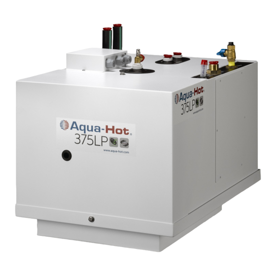
Aqua-Hot 375LP Installation Manual
Hide thumbs
Also See for 375LP:
- Installation manual (56 pages) ,
- Service manual (92 pages) ,
- Owner's manual (24 pages)
Table of Contents
Advertisement
Quick Links
WARNING: If the information in these instructions is
not followed exactly, a fire or explosion may result
causing property damage, personal injury, or death.
— Do not store or use gasoline or other flammable va-
pors and liquids in the vicinity of this or any other
appliance.
— WHAT TO DO IF YOU SMELL GAS
• Evacuate all persons from the vehicle.
• Shut off the gas supply at the gas container or
source.
• Do not touch any electrical switch or use any
phone or radio in the vehicle.
• Do not start the vehicle's engine or electric
generator.
• Contact the nearest gas supplier or qualified
service technician for repairs.
• If you cannot reach a gas supplier or qualified
service technician, contact the nearest fire
department.
• Do not turn on the gas supply until the gas leak(s)
has been repaired.
— Installation and service must be performed by a quali-
fied installer, service agency, or the gas supplier.
INSTALLATION MANUAL
AVERTISSEMENT. Assurez-vous de bien suivre les
instructions données dans cette notice pour réduire au
minimum le risque d'incendie ou d'explosion ou pour
éviter tout dommage matériel, toute blessure ou la
mort.
— Ne pas entreposer ni utiliser d'essence ou ni d'autres
vapeurs ou liquides inflammables à proximité de cet
appareil ou de tout autre appareil.
— QUE FAIRE SI VOUS SENTEZ UNE ODEUR DE GAZ :
• Évacuez le véhicule.
• Coupez l'alimentation en gaz au réservoir ou à la
source.
• Ne touchez à aucun interrupteur ; ne pas vous
servir du téléphone ou de la radio du véhicule.
• Ne pas démarrer le moteur du véhicule ni aucune
génératrice électrique.
• Appelez le fournisseur de gaz le plus proche ou un
technicien qualifié.
• Si vous ne pouvez rejoindre ni un fournisseur ni un
technicien qualifié, appelez le service des
incendies le plus proche.
• Ne pas rétablir l'alimentation en gaz tant que la
fuite n'a pas été réparée.
— L'installation et l'entretien doivent être assurés par
un installateur ou un service d'entretien qualifié ou
par le fournisseur de gaz.
© 2011 Aqua-Hot Heating Systems Inc.
Advertisement
Table of Contents

Related Manuals for Aqua-Hot 375LP


Summary of Contents for Aqua-Hot 375LP
- Page 1 — L’installation et l’entretien doivent être assurés par — Installation and service must be performed by a quali- un installateur ou un service d’entretien qualifié ou fied installer, service agency, or the gas supplier. par le fournisseur de gaz. INSTALLATION MANUAL © 2011 Aqua-Hot Heating Systems Inc.
- Page 2 CAUTION: The Aqua-Hot tank and heating loop operate at 0.0 psi (zero pressure system). Air pressure applied to the tank MUST NOT exceed 20 psi. Excess pressure will result in internal damage. CAUTION: Before welding or plasma cutting on any coach;...
-
Page 3: Table Of Contents
Section 1: Aqua-Hot Hydronic Heating System Technical Information .......................... 6 Section 2: Aqua-Hot Installation Installing the Mounting Tray and the Aqua-Hot................10 Overall Aqua-Hot Dimensions ......................12 Installing the Cable-Clamp Fittings ....................14 Installing the Wires into the Terminal Blocks .................. 14 Installing the Expansion Tank ...................... - Page 4 Purging the Domestic Water System....................43 Purging the Propane System ........................ 44 Section 11: Initial Start-Up Operating Safety Instructions ......................45 Activating the Aqua-Hot ........................46 Appendices: Appendix A: Wiring Diagram ......................47 Appendix B: Wire Gauge Information ....................48 Appendix C: Antifreeze Types ......................
-
Page 5: Introduction
NTRODUCTION The Aqua-Hot 375LP is a hydronic (water based) heating system, and a tank-less hot water system. Danger, Warning, Caution, and Note Boxes: Danger, Warning, Caution, and Note boxes appear The heating system provides moist, quiet, comforta- throughout this manual as a means of alerting the install- ble, interior heat with up to three separate, thermo- er to important information. -
Page 6: Section 1: Aqua-Hot Hydronic Heating System Technical Information
RVIA Standards, write to: Recreation Vehicle Industry Association, 1896 Preston White Drive, P.O. Box 2999, Reston, VA 22090-0999, call them at (703) 620-6003, or visit them online at www.rvia.org. — Page 6 — ® © 2011 Aqua-Hot 375-LP Installation Manual... - Page 7 1: A ECTION YDRONIC EATING YSTEM Each Aqua-Hot heating system possesses an I.D. label on the heater, to what standard it has been tested, and im- the unit itself. This I.D. label details the specifications of portant safety notices. Figure 2...
- Page 8 YSTEM Pump-1 Figure 3 Pump-2 I.D. Label Zone 1 and 2 Propane Inlet Outlet Ports Hot Water Outlet Port Terminal Block Cold Water Inlet Port Operating Instructions Site Access — Page 8 — ® © 2011 Aqua-Hot 375-LP Installation Manual...
- Page 9 YSTEM Figure 4 Interlock Switch Domestic Water Assembly Zone 1 Relay Zone 2 Relay Fuse Block Propane Burn- Controller Zone 2 Zone 1 Circulation Circulation Drain Valve Pump Pump — Page 9 — ® © 2011 Aqua-Hot 375-LP Installation Manual...
-
Page 10: Installing The Mounting Tray And The Aqua-Hot
Installing the Mounting Tray and the Aqua-Hot: Place the Aqua-Hot into the mounting tray. Reference Figure 9. The Aqua-Hot must be installed in a compartment that is NOTE:Be sure to complete the following when i completely closed-off from living quarters and accessible stalling the Aqua-Hot:: only from the outdoors. - Page 11 2: A ECTION NSTALLATION Figure 6 Underside of Mounting Tray Mounting Tray Flange (Installed in cut-out) Figure 7 — Page 11 — ® © 2011 Aqua-Hot 375-LP Installation Manual...
- Page 12 2: A ECTION NSTALLATION Figure 8 — Page 12 — ® © 2011 Aqua-Hot 375-LP Installation Manual...
- Page 13 2: A ECTION NSTALLATION Figure 9 — Page 13 — ® © 2011 Aqua-Hot 375-LP Installation Manual...
-
Page 14: Installing The Cable-Clamp Fittings
Aq- ua-Hot. NOTE: A ferrule is required if stranded wire is being used to connect to the terminal block Figure 10 Figure 11 — Page 14 — ® © 2011 Aqua-Hot 375-LP Installation Manual... -
Page 15: Installing The Expansion Tank
Installing the Expansion Tank: NOTE: Avoid dips and bends in the overflow tubing from the Aqua-Hot to the expansion tank as air can become trapped in these dips and bends, pre- Select a mounting location that allows for easy ac-... -
Page 16: Heat Exchanger Location And Clearances
Figure 13 Figure 15 Indicates sample mounting locations for the Cozy Heat exchangers. Actual placement and quantity vary based on the individual design of the coach. For specific design assistance, contact Aqua-Hot at 303-659-8221 — Page 16 — ® © 2011 Aqua-Hot... -
Page 17: Mounting The Heat Exchangers
Figure 18 Hose to direct Cozy Heat air to vent Exchanger Plenum Toe Kick Board Vent installed In toe-kick area — Page 17 — ® © 2011 Aqua-Hot 375-LP Installation Manual... - Page 18 3: H ECTION YDRONIC EATING YSTEM Figure 20 Figure 21 — Page 18 — ® © 2011 Aqua-Hot 375-LP Installation Manual...
-
Page 19: Sample Heating System Floorplan
3: H ECTION YDRONIC EATING YSTEM — Page 19 — ® © 2011 Aqua-Hot 375-LP Installation Manual... -
Page 20: Wiring The Heat Exchangers
Terminal for Heating 4. Attach each zone wire ran in step 2 to the Aqua-Hot Zone 2’s positive heat terminal block - position F1 for zone 1 and position exchanger wire (F2) F2 for zone 2. - Page 21 When wiring the heat exchangers in-parallel, the main grounded, respectively. 18-gauge wire is split to allow the heat exchanger wires to combine with the main wire to be powered or Figure 25 — Page 21 — ® © 2011 Aqua-Hot 375-LP Installation Manual...
-
Page 22: Plumbing Requirements
(typically 3) must be plumbed together mulate a plan for the routing of the plumbing lines from each heating zone to the Aqua-Hot. in-series on “Heating Loop 2.” Reference Figure All plumbing lines should be laid as flat as possible, Use 5/8 inch I.D. -
Page 23: Plumbing The Hydronic Heating System
Rubber Coated/Closed-Type clamps are recommended when securing the plumbing lines. 5. Connect and tighten all interior plumbing lines, outlet and inlet, to the Aqua-Hot’s appropriate 3. Connect and clamp the outlet line from the heat- heating loop ports. Reference Figure 29 and Fig- er to the lowest port on the heat exchanger with ure 30. - Page 24 ECTION YDRONIC EATING YSTEM Figure 28 Figure 29 Inlet Heating Loop Connection Examples Barbed Fittings Components Compression Fitting Compo- nents Compression Fittings Components In- Barb Fittings Components Installed stalled — Page 24 — ® © 2011 Aqua-Hot 375-LP Installation Manual...
- Page 25 3/4” Pex Tube Heater Two Constant Tension Hose Band Clamps Pex Insert Constant Tension Clamps Components Connection Straight Connection 90⁰ Components Connection Components 90⁰ Components Installed Straight Connection Installed — Page 25 — ® © 2011 Aqua-Hot 375-LP Installation Manual...
-
Page 26: Fresh Water Tank Thermostat
Thermostat Front View Figure 31 stat’s second terminal. Thermostat Rear View Terminals Mounting Holes Capillary Tube Black wire from Heat Exchanger to chassis ground Red Wire from Heat Exchanger Bulb — Page 26 — ® © 2011 Aqua-Hot 375-LP Installation Manual... -
Page 27: Room Thermostats
NOTE: The selected location should prevent the 1. Run one 18-gauge wire from each room thermo- thermo stat from being affected by: stat mounting location to the Aqua-Hot terminal • drafts or dead spots behind doors and in block. corners 2. -
Page 28: Domestic Water System Requirements
2. Connect a domestic water plumbing line from the Aqua-Hot’s hot water outlet port to the hot water system’s distribution lines/water manifold. NOTE:A water heater or ice maker shall not be counted Reference Figures 33 and 34. - Page 29 To Hot Water Faucets Domestic Hot Water Outlet Domestic Cold AT—Indicates Options Water Inlet for mounting an Accumulator Tank To Cold Water Faucets Fresh Water Storage Tank Demand Pump — Page 29 — ® © 2011 Aqua-Hot 375-LP Installation Manual...
-
Page 30: Switch Panel Location
1. Run 16-gauge wires from the switch panel to the NOTE:It is recommended that the wire numbers in Ap- Switch Panel Mounting: pendix A be used when installing the Aqua-Hot in order to aid service personnel with troubleshoot- ing. 1. Cut out a 2.5” W x 1.75” H opening for the switch panel plate. - Page 31 Jump to Pin # 2 Pin# 9 Terminal Block L- Pin# 9 Chassis Ground Burner Switch to Electric Element Switch to Terminal Block Connections Terminal Block Connections Figure 37 — Page 31 — ® © 2011 Aqua-Hot 375-LP Installation Manual...
-
Page 32: Propane Connection Requirements
1. Check the Recreational Vehicle’s propane mani- leaks. fold for an available 3/8 inch port for the pro- pane supply line to the Aqua-Hot’s propane inlet To avoid possible propane gas leaks, always port. use two wrenches to tighten or loosen the gas supply line connectors. - Page 33 1/2 psi (3.5 kPa). less than 1/2 psi (3.5 kPa). Figure 39 Manual Shut-Off Valve for Propane Supply Installed in Propane Inlet Port — Page 33 — ® © 2011 Aqua-Hot 375-LP Installation Manual...
- Page 34 This Page Intentionally Left Blank ® © 2011 Aqua-Hot 375-LP Installation Manual...
-
Page 35: Exhaust System Requirements
Exhaust should not exceed 14 feet. • WARNING! NOTE: Should the particular application require more The Aqua-Hot’s exhaust is hot and must be kept away than 14 feet of exhaust pipe, please contact the from any heat-sensitive material. Aqua-Hot Heating Systems Product Application Department at 1-800-685-4298 for assistance. - Page 36 8: E ECTION XHAUST YSTEM Figure 42 Figure 43 — Page 36 — ® © 2011 Aqua-Hot 375-LP Installation Manual...
- Page 37 8: E ECTION XHAUST YSTEM Figure 44 — Page 37 — ® © 2011 Aqua-Hot 375-LP Installation Manual...
- Page 38 Nipple Installed Black Pipe Elbow 4” Black Pipe Nipple Installed 2” Automotive Type Exhaust Pipe Figure 46 Vehicle’s Exhaust Pipe #8, 3/8” #8, 3/8” sheet- metal screw Exhaust Tip — Page 38 — ® © 2011 Aqua-Hot 375-LP Installation Manual...
-
Page 39: Connecting The 12 Volt-Dc Power
Follow the instructions in this section for “Installing the Wires into the Terminal Blocks” for the 120 Volt- AC wires. DO NOT connect the 12 Volt-DC power to the Aqua-Hot if the vehicle requires welding. Electrical welding will cause serious damage to the burner controller. - Page 40 Tighten the terminal block screws to 5 inch-pounds using a slotted blade, no larger than 1/8”, when attaching the 120V AC wires to the terminal block. Figure 48 Main Battery Disconnect — Page 40 — ® © 2011 Aqua-Hot 375-LP Installation Manual...
-
Page 41: Purging The Hydronic Heating System
In order to provide the best freeze protection, boil- deemed “GRAS” (Generally Recognized as Safe) by over protection, and anti-corrosion and rust protec- the FDA shall be used in the Aqua-Hot’s hydronic tion, a mixture of “GRAS” approved propylene gly- heating system. Failure to use the above specified col antifreeze and water is recommended. -
Page 42: Purging The System By Grounding The Zone Thermostat Connection
F on Page 52. filling procedure. 6. Allow the circulation pump to operate for ap- 4. Open the Aqua-Hot’s drain valve located at the proximately 1-3 minutes in order to purge the front of the heater. Reference Figure 50. corresponding heating loop, then remove the 5. -
Page 43: Purging The Domestic Water System
ECTION URGING THE YSTEMS Purging the Domestic Water System: 10. Check the Aqua-Hot’s expansion tank and top it CAUTION off to the cold level mark with the antifreeze and water solution, if necessary. Verify that the domestic water tank contains fresh water 11. -
Page 44: Purging The Propane System
1. Ensure that the propane line from the RV pro- leaks. pane tank to the Aqua-Hot has propane availa- 6. Ensure that the interior room thermostats are set ble. to their highest position in order to call for heat, 2. -
Page 45: Operating Safety Instructions
11: I ECTION NITIAL TART — Page 45 — ® © 2011 Aqua-Hot 375-LP Installation Manual... -
Page 46: Activating The Aqua-Hot
ECTION NITIAL TART Activating the Aqua-Hot: 1. Ensure that the Aqua-Hot’s main access cover is fully installed and securely fastened as a safety switch exists requiring installation of the access cover for operation. 2. Ensure that an adequate supply of the antifreeze and water heating solution exists by checking the level at the expansion tank. -
Page 47: Appendix A: Wiring Diagram
A: W PPENDIX IRING IAGRAM —... -
Page 48: Appendix B: Wire Gauge Information
B: W PPENDIX AUGE NFORMATION... -
Page 49: Appendix C: Antifreeze Types
“boiler” type anti- antifreeze is not formulated to transfer heat, which is freeze in the Aqua-Hot. Propylene glycol is a safer essential to the heating system’s functionality and alternative to the more toxic ethylene glycol anti- does not contain rust inhibitors. -
Page 50: Appendix E: Antifreeze Terms And Mixture Ratio
222ºF. change from a liquid to a gas. NOTE: As the installer of this Aqua-Hot system, you must refer to the information and chart in Appendix E Rust and Anti-Corrosive Inhibitors:... - Page 51 E: A PPENDIX NTIFREEZE ERMS AND IXTURE ATIO — Page 51 —...
-
Page 52: Appendix F: Measuring Propylene Glycol Using A Refractometer
F: M PPENDIX EASURING ROPYLENE LYCOL SING A EFRACTOMETER ALIBRATE THE EFRACTOMETER Aqua-Hot Part Number MSX-907-162 Figure 1 Calibration Screw Eyepiece Daylight Plate Assembly Main Prism Assembly ® © 2011 Aqua-Hot 375-LP Installation Manual... - Page 53 EFRACTOMETER SING THE REFRACTOMETER TO TEST ANTIFREEZE SAMPLE Warning Use extreme caution in gathering your antifreeze sample. When draining the Aqua-Hot heating system. ex- tremely hot liquid may be in the Boiler Tank and could cause personal injury. Basic Operation 1.
- Page 54 OTES ® © 2011 Aqua-Hot 375-LP Installation Manual...
- Page 55 OTES ® © 2011 Aqua-Hot 375-LP Installation Manual...
- Page 56 15549 East Highway 52 | Fort Lupton, CO 80621 Toll free: 800.685.4298 | phone: 303.659.8221 | fax:303.857.9000 www.aquahot.com LTE-375-016 Rev C...
Need help?
Do you have a question about the 375LP and is the answer not in the manual?
Questions and answers