Table of Contents
Advertisement
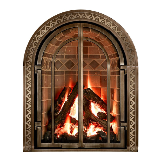
OPEN HEARTH TRUE ARCHED GAS DIRECT VENT FIREPLACE
INSTALLATION & OPERATING INSTRUCTIONS MANUAL
Do not store or use gasoline or other flammable
vapors and liquids in the vicinity of this or any
other appliance.
WHAT TO DO IF YOU SMELL GAS
•
Open windows.
•
Do not touch electrical switches.
•
Do not try to light any appliance.
•
Extinguish any open flame
•
Do not use the phone in your building.
•
Immediately call your gas supplier from a neighbor's
phone. Follow the gas supplier's instructions.
•
If you cannot reach your gas supplier, call the fire
department.
In the Commonwealth of Massachusetts:
•
Installation must be performed by a licensed plumber or
gas fitter;
•
A CO detector shall be installed in the room where the
appliance is installed.
WARNING
If the information in this manual is not followed exactly, a
fire or explosion may result causing property damage,
personal injury or loss of life.
WARNING
Do NOT use this appliance if any part has been under water.
Immediately call a qualified service technician to inspect the
appliance and to replace any part of the control system and
any gas control, which has been under water.
CHELSEA
Model M-27
DOCUMENT NO. M27-0906
WARNING: Improper installation, adjustment, altera-
tion, service or maintenance can cause injury or prop-
erty damage. Refer to this manual. For assistance or
additional information consult a qualified installer, ser-
vice agency or the gas supplier.
A qualified installer, service agency, or the gas sup-
plier must perform installation and service.
Do not store or use gasoline or other flammable va-
pors and liquids in the vicinity of this or any other ap-
pliance.
Do not operate this appliance with the glass removed,
cracked or broken. A licensed or qualified person
should do replacement of glass.
Mendota gas fireplaces are heat producing appliances.
Do not burn wood, paper or other materials in this fire-
place. This fireplace is designed as a supplement
heat source. It is advisable to have an alternative pri-
mary heat supply.
The installation must conform with local codes or, in
the absence of local codes, with the current National
Fuel Gas Code, ANSI Z223.1, or the current Natural
Gas and Propane Installation Code, CSA B149.1
THESE INSTRUCTIONS ARE TO REMAIN WITH
THE HOMEOWNER.
FOR YOUR SAFETY
WARNING
WARNING
CAUTION
Advertisement
Table of Contents

Related Manuals for Mendota CHELSEA M-27


Summary of Contents for Mendota CHELSEA M-27
- Page 1 Installation must be performed by a licensed plumber or WARNING gas fitter; Mendota gas fireplaces are heat producing appliances. • A CO detector shall be installed in the room where the Do not burn wood, paper or other materials in this fire- appliance is installed.
-
Page 2: Table Of Contents
BURNER FLAMES GENERAL HEIGHT DIAGRAM..........................63 NATURAL TO LP GAS CONVERSION..............................64 LP GAS PRESSURE REQUIREMENTS ..............................65 VALVE ASSEMBLY REPLACEMENT PARTS............................68 GLASS FRAME ASSEMBLY REPAIR AND REPLACEMENT.........................69 MENDOTA WARRANTY QUALIFICATION & SERVICE REFERENCE FORM ..................70 MENDOTA EXTENDED LIFETIME PROTECTION AND LIMITED WARRANTY..................75 - 2 -... -
Page 3: Safety And Warning Information
SAFETY AND WARNING INFORMATION READ and UNDERSTAND all instructions carefully before starting the appliance. FAILURE TO FOLLOW these instruc- tions may result in a possible fire hazard and will void the warranty. Any safety screen or guard removed for servicing must be replaced before operating this appliance. DO NOT USE this appliance if any part has been under water. -
Page 4: Specific Requirements For The Common Wealth Of Massachusetts
Specific Requirements for the Common Wealth of Massachusetts The information in this section applies to all installations performed in the Common Wealth of Massachusetts only. For all side wall horizontally vented gas fueled equipment installed in every dwelling, building or structure used in whole or in part for residential purposes and where the side wall exhaust vent termination is less than seven (7) feet above grade, the following requirements shall be satisfied: 1. - Page 5 SPECIFICATIONS MODEL M-27 High Fire - Adjustable to - Low Fire BTUH. (MODEL M-27) NAT. GAS 27,000 6,750 BTUH. (MODEL M-27) LP GAS 25,000 7,000 NOTE: LPG CONVERSION KIT, #HA-48-00025, MUST BE PURCHASED SEPARATELY TO CONVERT TO BURN LPG IN THIS FIREPLACE. MAIN ORIFICE [0-2000ft (610 m)]: REAR BURNER: #45 NAT.
-
Page 6: Congratulations
Fireplace and replace any part of the control system and any gas control, which has been under water. DO NOT use this fireplace if the burner does not light immediately. Turn unit off and call Mendota ap- proved service person if there is any delay in burner light off. -
Page 7: General Appliance Specifications
M-27 GAS DIRECT VENT FIREPLACE GENERAL APPLIANCE SPECIFICATIONS Figure 1: General Appliance Specifications 34 3 4 " 29 1 2 " MIN. 24 5 8 " FRAMING WIDTH 11-1/4" 5-1/2" TO VENT 20 5 8 " 1" 1" MINIMUM PIPE CENTER 3.7255 2.5478 14"... -
Page 8: Mantel Clearances
MANTEL CLEARANCES Mantel Clearances for this fireplace may be measured from the top of the convection air opening or the floor level of this fireplace. The location that is referenced normally to measure mantel clearances is the Top of 8" DEEP COMBUSTIBLE MANTEL the Convection Air Opening. -
Page 9: Clearances To Combustibles From Appliance Surfaces
CLEARANCES TO COMBUSTIBLES FROM APPLIANCE SURFACES Figure 3: Clearances to Combustibles CLEARANCE FROM TOP OF ARCHED OUTER SKIN TO COMBUSTIBLE FRAMING 1-5/8" MINIMUM - 9 -... -
Page 10: Planning The Installation
PLANNING THE INSTALLATION When planning on appliance installation, it is necessary to determine the following information before installing: • Where the appliance is to be installed. • The vent system configuration to be used. • Gas supply piping. • Electrical Wiring. •... -
Page 11: Framing Dimensions
FRAMING DIMENSIONS Minimum Rough Framing Dimensions DIMENSION DESCRIPTION (INCHES) Width 29-1/2 Height DEPTH (assumes that 3/4” thick plywood is used as facing material. Reduce depth 13-1/4 (C) for thicker facing materials. See Fac- ing Materials Section.) Vent opening height 10-1/4 Vent opening width 9-1/4 Rough Framing Height... -
Page 12: Framing Depth & Finishing Material
Framing Depth & Finishing Material 14.00 12.00 min Figure 7: Framing Depth 2.00 Framing Sub Layer Finish Material Finish Max. 1" min Material Framing Thickness Depth ½” 13 ½” ¾” 13 ¼” 1” 13” 1 ¼” 12 ¾” 1 ½” 12 ½”... -
Page 13: Elevated Framing Dimensions
ELEVATED FRAMING DIMENSIONS This fireplace may be installed in an elevated position by created an elevated deck and an appropriate framed en- closure. NOTE: This fireplace may be elevated but MUST allow a minimum of 60” distance between this fireplace’s floor level and the ceiling. -
Page 14: General Information
The M-27 Fireplace must be installed and serviced by a Mendota approved serviceperson. Any adjustments to burner, pilot, logs or coal bed must be made by a Mendota approved service person. Pilot system voltage must be checked with a voltmeter. -
Page 15: Gas Supply Requirements
FRONT Correct gas pressure and proper gas supply line sizing is imperative to the successful performance of your Mendota gas fireplace. Be sure the gas supplier or plumber carefully checks for correct gas pressure and gas line sizing when installing the fireplace. -
Page 16: Gas Pressure Requirements
GAS PRESSURE REQUIREMENTS ONE MAJOR CAUSE OF OPERATING PROBLEMS WITH GAS APPLIANCES CAN BE IMPROPER GAS PRESSURE! Problems such as changes in flame color or configuration, gas pilot or burner outages, intermittent operation, changes in heat output, excessive burner noise, etc. are nearly always the result of changes in gas pressure or improper gas pres- sure at the time of the installation. -
Page 17: General Installation Instructions
National Fuel Gas Code. In the absence of local codes, the installation must conform to the most current edition of the National Fuel Gas Code ANSI Z223.1, also known as NFPA 54. NOTE: The Mendota M-27 Fireplace is approved for mobile home and bedroom installations. -
Page 18: General Flue Venting Instructions
Common vent systems are prohibited. To assure proper venting performance of this high-performance Mendota Direct Vent Fireplace, it is critical that all brands of vent pipe sections are sealed tightly and leak-proof. This means that all pipe sections must be carefully rotated into the fully "twist-locked"... -
Page 19: Exterior Vent Locations And Restrictions
EXTERIOR VENT LOCATIONS AND RESTRICTIONS ALL MEASUREMENTS FROM CENTER LINE OF VENT CAP Figure 14: Exterior Vent ∨ - ∧ - ≡ - Vent Terminal Air Supply Inlet Area where terminal is not permitted Clearance above grade, veranda, porch, deck, or bal- *Not to be installed above a meter/regulator assembly cony (*12 inches (30 cm) minimum). -
Page 20: Flue Venting Components Identification
FLUE VENTING COMPONENTS IDENTIFICATION ITEM DESCRIPTION 6" or 7” PIPE (DuraVent 6”/Amerivent 7”) 12" VENT STACK 24" VENT STACK 36" VENT STACK 48" VENT STACK 90ºGALVANIZED ELBOW 45º GALVANIZED ELBOW ADJUSTABLE WALL THIMBLE ATTIC INSULATION SHIELD 12" ROOF FLASHING (0/12 TO 6/12) ROOF FLASHING (7/12 TO 12/12) STORM COLLAR VERTICAL VENT CAP... -
Page 21: Master Flue Venting Requirements Chart
MASTER FLUE VENTING REQUIREMENTS CHART NOTE: THIS CHART IS APPLICABLE TO BOTH NATURAL GAS AND LPG INSTALLATIONS. IMPORTANT NOTES: Figure 16 V min H max 0 in. 48" 6 in. 9'6" 12 in. 18 in. 16'6" 24 in. 6" 30 in. 17'6"... -
Page 22: Important Venting Configuration Notes
IMPORTANT VENTING CONFIGURATION NOTES See Figure 16 [MASTER FLUE VENTING REQUIREMENTS CHART]. MAXIMUM HORIZONTAL RUN A. Maximum Horizontal Run allowed is 20 feet if a vertical starter section that is between 4 feet to 25 feet is con- nected directly to this fireplace’s flue starter collar and only one 90 degree elbow is used. B. -
Page 23: Approved Vent Systems
APPROVED VENT SYSTEMS QUICK REFERENCE CHART Figure 17: Vent Systems ZERO VERTICAL VERTICAL RISE STRAIGHT UP, VERTICAL VENTING HORIZONTAL TERMINATION HORIZONTAL TERMINATION 45 FEET MAXIMUM APPROVED APPROVED APPROVED VERTICAL RISE ZERO VERTICAL VERTICAL RISE DUAL 90° ELBOWS DUAL 90° ELBOWS DUAL 90°... -
Page 24: Zero Rise Horizontal Termination
ZERO RISE HORIZONTAL TERMINATION The M-27 Fireplace must be installed by a qualified Mendota approved serviceperson. A Maximum Horizontal Run allowed is 4 feet if a 90-degree elbow is connected directly to this fireplace’s flue starter collar. When a 90-degree elbow is connected directly to this fireplace, the horizontal centerline of the 90ºelbow will be 44-9/16”... -
Page 25: Vertical Rise Horizontal Termination
This will cause high temperatures and the possibility of a fire. This M-27 Fireplace must be installed by a qualified Mendota service person 1. Position fireplace in desired location. See Figure for guidelines on proper vent cap placement on exterior of home. -
Page 26: Horizontal Termination
Figure 22 H1+H2 max V max 6" 6' 6" 42'-H1-H2-V1 42'-H1-H2-V1 42'-H1-H2-V1 15' 6" 42'-H1-H2-V1 4'-25' 42'-H1-H2-V1 FOR V GREATER THAN 25', SEE FIGURE 16 ON PAGE 20 V1 min = 6" H1 min = 0 H2 min = 6" THREE (3) 90°... -
Page 27: Vertical Through-The-Roof Venting
Doing so will continue to allow the use of the 45 feet maximum vertical run. The M-27 Fireplace must be installed by a qualified Mendota approved serviceperson. 1. Place the fireplace in its desired location. Drop a plum bob from the ceiling to the position of the fireplace flue exit. - Page 28 Height "*H" of top of vent cap can be determined as follows: "H" DIMENSION ROOF PITCH FEET METERS FLAT to 6/12 7/12 to 9/12 10/12 to 12/12 13/12 to 16/12 17/12 to 21/12 9. Complete installation with storm collar and vent cap. Figure 24 45 FEET MAXIMUM...
- Page 29 THREE(3) 90° ELBOWS WITH STARTER VERTICAL SECTION VERTICAL TERMINATION V1 + H1 + V2 + H1 + H2 max H2 max 6" 6' 6" 12" 12' 6" 4'-25' FOR V GREATER THAN 25', SEE FIGURE 6 ON PAGE X V1 min = 6" V1 + H1 + H2 + V2 (max) = 34' Figure 25 THREE(3) 90°...
-
Page 30: M-27 Door Operation
M-27 DOOR OPERATION TO REMOVE DOOR Use the tool to disconnect the spring latches from the glass frame. Insert tool into hole in latch, pull towards you and up to disengage latch. There are four spring latches, two on top and one on each side. With both hands, rotate glass frame away from unit a few inches. -
Page 31: To Replace Door
TO REPLACE DOOR 1. Line up tabs on glass frame with slots in glass clips on firebox. Insert tabs into slots. Figure 31 2. After door has been placed into slots, rotate door towards firebox until gasket seal is touching the firebox frame. Figure 32 - 31 -... - Page 32 3. Use the tool provided to connect the spring latches to the glass frame. Insert tool into hole in spring latch, pull latch up and towards you, then down into slot in glass frame until it catches. Figure 34 4. Door is now connected and sealed to unit. Figure 35 - 32 -...
-
Page 33: Refractory Liner Removal And Installation Procedures
REFRACTORY LINER REMOVAL AND INSTALLATION PROCEDURES Introduction: The Mendota M-27 Gas Fireplace is shipped with a ONE PIECE domed refractory liner factory installed inside the fire- box. M-27 model fireplaces with part number AA-11-00847 are equipped with a Red Chicago Style (Clinker) Brick patterned refractory liner. - Page 34 Step 3: See Diagrams on this page and follow instructions to loosen brick panel if it is tightly fit inside the firebox. The same procedures apply for all style refractory liners. - 34 -...
- Page 35 Step 4: Keep the Front-Bottom of the Refractory Liner Stationery and rotate the top domed edge forward and out of the firebox. ROTATE TOP FORWARD Step 5: Use one hand to support the Refractory Liner’s Dome area from the inside surface. Lift the Refractory Liner up and slide it out of the Firebox horizontally.
- Page 36 Step 7: Once Refractory Liner is inside the firebox, push rear surface of refractory liner against rear wall of Firebox, firmly. Step 8: Install Refractory Retainer Bracket (supplied with the Owner’s Manual Packet as shown in the diagrams, below. The Refrac- tory Retainer Bracket must be installed in the same orientation as shown in the detail view below.
-
Page 37: M-27 Log Set Installation Instructions
M-27 LOG SET INSTALLATION INSTRUCTIONS 1. Cut the clear tapes and outer plastic wrap using a sharp utility knife or equivalent. Locate the 2 bags of coals, glowing embers and the log pieces. Identify each log piece numbered A through G and the Large Chunk coals (H), Small coals (I) and Glowing Embers (J) per the diagram show on this page. - Page 38 Identify the REAR LOG PINS and the MAIN EMBER BED PINS that are pressed onto the Burner Air box. - 38 -...
- Page 39 - 39 -...
- Page 40 - 40 -...
- Page 41 - 41 - - 41 -...
- Page 42 - 42 -...
- Page 43 - 43 -...
- Page 44 - 44 -...
- Page 45 The completed log set shall look as depicted in the Step 14, above. Add small coals (I), first, in the area between the firebox front edge and the grate bars. Also add small coals (I) in front and behind the front burner. When adding the small coals, space them ½ inches apart, left to right, to allow combustion air to flow to burner ports.
-
Page 46: M-27 Surround Kit
M-27 SURROUND KIT INSTALLATION INSTRUCTIONS INTRODUCTION ITEM DESCRIPTION The surround kit, available for the M27 (Chelsea) fireplace, com- SURROUND TOP pletes the installation. The surround kit is designed to cover the ex- terior structural parts and surfaces of this fireplace. It also provides SURROUND LEG, LEFT HAND for easy access to the commonly used control panels located on the SURROUND LEG, RIGHT HAND... - Page 47 SURROUND KIT INSTALLATION INSTRUCTIONS 1. Positively identify the Left Hand and Right Hand Surround Legs. The Pull Handle must be located in the bottom half of the surround leg. Use this item to identify the Left Hand and Right Hand Surround Legs. NOTE: If the Pull Handles are not factory-assembled, attach one pull handle on each (left hand and right...
- Page 48 2. Lay the four main surround parts (Top, Left Hand Leg, Right Hand Leg and Bottom) on the floor with their visible sides facing upwards. See Figure, below. 3. Insert one 1/8” X 1” Hinge Pin into the top and bottom Hinge Pin Holes in the Left Hand and Right Hand Surround Legs.
- Page 49 7. Identify and attach the Left Hand and Right Hand Temporary Braces as shown, below. These braces are designed to keep the assembly as a ONE_PIECE ASSEMBLY during the installation process. These temporary braces will prevent the Left Hand and Right Hand Surround Legs from closing fully. This is normal. 8.
- Page 50 9. Before attaching Surround Assembly to the fireplace, remove the Hearth Pad Spacer that is secured to the Floor Plate of the Fireplace. See Figure X. Remove the two ¼” Hex Head Screws that secure the Hearth Pad Spacer to the Fireplace and slide it out and discard.
- Page 51 12. Carefully, stand the Surround Assembly upright. Slide the three (3) studs [attached to the Surround Bottom] into the three open slots in the fireplace floor plate’s front flange. Do not tighten the nuts at this time. 13. Rotate entire Surround Assembly in towards the fireplace. 14.
- Page 52 15. Make certain that TOP CENTER CLIP on the back of the Surround Top slides under the inner shield of the fire- place. CLIP INNER SHIELD TOP MAKE SURE CLIP SLIDES INNER SHIELD BELOW INNER SHIELD TOP ITEM 1 CLIP 16.
- Page 53 18. Remove and discard the Left Hand and Right Hand Temporary Braces. SURROUND 1/32" 19. Adjustment and Alignment Instructions for Sur- round Rotate left hand and Right Hand Surround Legs closed. Check alignment of Left Hand Surround Leg and Right Hand and Surround Bottom This Surround Leg to Surround Top...
-
Page 54: Installation Check Off List
The following Check Off Lists must be completed prior to final operation of the Fireplace. INSTALLATION CHECK OFF LIST Co-axial vent rigid pipe, wall vent cap or roof vent cap must be installed by a Mendota approved person in accordance with instructions. All joints must be secured, "twist- locked"... -
Page 55: Lighting Instructions
LIGHTING INSTRUCTIONS IMPORTANT: Be sure all items on "INSTALLATION CHECK OFF LIST" (PG. 44) have been completed! CAUTION: If the pilot goes out, be sure to wait a minimum of five minutes before relighting - be sure to always remove the glass before relighting the pilot. - Page 56 NOTE: The rear burner is controlled by a 9 Volt DC solenoid valve. One 9 Volt cell battery (located behind the control panel) provides power for this unique feature. Replace with a new high quality 9 Volt battery annually. 18. Open windows for first four hours of operation. NOTICE: Initial heater start-up will cause some NON TOXIC "off gassing"...
-
Page 57: Thermostat Operation And Wall Switch Kit Connections
60 seconds and repeat lighting procedure. If burner does not come on immediately after second try recheck complete installation. If necessary, contact your Mendota dealer. CAUTION: THIS CONTROL IS A MILLIVOLT SYSTEM. NO ADDITIONAL POWER SUPPLY CAN OR SHOULD BE USED. -
Page 58: Making Wire Connections To Wall Switch Kit #Aa-11-00781
NOTE: This wall switch kit does not provide thermostatic control of the fireplace or insert. If you desire to control your Mendota Fireplace or Insert thermostatically, you must install a Millivolt rated wall thermostat. Contact your Mendota Dealer for detailed information and availability of an appropriate thermostat. -
Page 59: Blower System Information
BLOWER SYSTEM INFORMATION WARNING: Label all wires prior to disconnection when servicing controls. Wiring errors can cause improper and dangerous operation. Verify proper operation after servicing. Dual blowers are provided as standard equipment with this M-27 fireplace. The dual blowers have an air output rating of 210 CFM (in free air). -
Page 60: Trouble Shooting The M-27 Fireplace
If sooting continues, open air shutter on burner (see "Gas Flame Adjust- ment" below). If sooting still continues, shut off unit and call Mendota service person. NOTE: To clean glass - remove glass and wipe glass with cloth or paper towel. -
Page 61: Customer Information
(usually a thin black film on the Fireplace viewing glass or on the outside of the home around the vent cap), the unit must be immediately turned off and the local Mendota dealer promptly informed. Mendota dealers will correct "sooting"... -
Page 62: Maintenance
MAINTENANCE 1. ANNUAL MAINTENANCE OF MENDOTA UNITS IS REQUIRED. The following procedures must be performed each year by a Mendota approved service person. NOTE: Any adjustments to burner, pilot or logs must be done by a qualified Mendota service person. -
Page 63: Burner Flames General Height Diagram
BURNER FLAMES GENERAL HEIGHT DIAGRAM This conversion kit shall be installed by a qualified service agency in accordance with the manufacturer’s instructions and all applicable codes and requirements of the authority hav- ing jurisdiction. If the information in these instructions is not followed exactly, a fire, explo- sion or production of carbon monoxide may result causing property damage, personal injury or loss of life. -
Page 64: Natural To Lp Gas Conversion
NATURAL TO LP GAS CONVERSION Kit #HA-48-00025 for Mendota Model M-27 Caution: The electrical supply to the fireplace must be turned off prior to performing the conversion. The gas supply must be shut off prior to disconnecting the electrical power. -
Page 65: Lp Gas Pressure Requirements
LP GAS PRESSURE REQUIREMENTS Inlet and manifold gas pressure checking taps are located on gas valve. A qualified installer shall take pressure meas- urements at these ports to verify and set the correct gas pressures during the LP Kit installation. Manifold pressure must be taken at the “MANIFOLD PRESSURE"... - Page 66 COMBUSTION SYSTEM MILLIVOLT READING Millivolt readings must be taken by a qualified installer once the LPG conversion kit parts have been installed. These readings will establish proper thermopile millivolt generation and assure trouble-free burner operation. Read- ings must be taken with: a.) Pilot ONLY operating.
- Page 67 ATTACHING LPG CONVERSION LABELS AND HIGH ALTITUDE DERATION LABEL Two printed informational labels are included with the LPG Conversion Kit. Attach these two labels to inner surface of the left side controls access door. If you are derating this appliance at a high altitude, also attach the High Altitude Deration Label, supplied in the Owner’s Manual Packet, to this same surface.
-
Page 68: Valve Assembly Replacement Parts
VALVE ASSEMBLY REPLACEMENT PARTS Figure 50: VALVE ASSEMBLY NG PRESSURE REGULATOR LP PRESSURE REGULATOR ITEM PART NO DESCRIPTION ITEM PART NO DESCRIPTION 60-05-00049 ELBOW, STREET, 1/2 MPT/ 1/2 FPT, BLACK 05-02-00313 VALVE, SIT, NATURAL GAS, 225F, 3.5-1.3 05-02-00289 NG PRESSURE REGULATOR (3.5-1.3”WC) 05-02-00310 VALVE, SOLENOID 65-06-00987... -
Page 69: Glass Frame Assembly Repair And Replacement
GLASS FRAME ASSEMBLY REPAIR AND REPLACEMENT DO NOT substitute other manufac- turer's materials or components. WARNING WARNING DO NOT operate unit with cracked, Use only authorized parts and Do not operate this appliance broken or missing glass. materials obtained from Johnson with the glass removed, cracked GASKET Gas Appliance Company when... -
Page 70: Listing Label Information
LISTING LABEL INFORMATION The model information regarding your specific appliance can be found on the rating plate, which is located inside the right side controls access door. When contacting your dealer for any cleaning service or warranty service, always provide the Model Number, Serial Number and Manufactured Date. -
Page 71: Mendota Warranty Qualification & Service Reference Form
As a part of Mendota's on-going program of customer satisfaction, this Form verifies proper installation and operation. It is im- portant as a reference for future service. It insures long life and trouble-free operation of Mendota fireplaces & stoves and quali- fies the owner for Mendota's lifetime limited warranty. - Page 72 NOTES - 72 -...
- Page 73 NOTES - 73 -...
- Page 74 TAPE SHUT --------------------------------------------------------------------------------------------------------------------------------------------------------- POSTAGE NEEDED JOHNSON GAS APPLIANCE COMPANY 520 E AVENUE N.W. CEDAR RAPIDS, IA 52405 - 74 -...
-
Page 75: Mendota Extended Lifetime Protection And Limited Warranty
The use of unauthorized components will make this warranty null and void. This warranty shall be effective only if the original purchaser of the Mendota appliance is registered with Mendota Division within thirty (30) days of the date of purchase. Such registration or the failure to register shall not be deemed to create any obligation or liability by the manufacturer and this warranty with its conditions and limitations shall be the only procedure for obtaining any rights against the manufacturer and expresses the sole obligation and re- sponsibilities of the manufacturer which are offered to the original purchaser and accepted upon purchase of the appliance. - Page 76 Johnson Gas Appliance Company 520 E Avenue N.W. - Cedar Rapids, IA 52405 Mendota Hearth Division WEBPAGE: www.johnsongas.com www.mendotahearth.com Part #85-03-00702...
Need help?
Do you have a question about the CHELSEA M-27 and is the answer not in the manual?
Questions and answers