Sign In
Upload
Manuals
Brands
GRASS VALLEY Manuals
Switch
1200
GRASS VALLEY 1200 Manuals
Manuals and User Guides for GRASS VALLEY 1200. We have
1
GRASS VALLEY 1200 manual available for free PDF download: Installation And Service
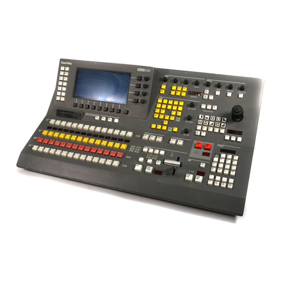
GRASS VALLEY 1200 Installation And Service (156 pages)
DIGITAL PRODUCTION SWITCHER
Brand:
GRASS VALLEY
| Category:
Switch
| Size: 1.64 MB
Table of Contents
Related Publications
2
Table of Contents
3
Important Safeguards and Regulatory Notices
11
Symbols and Their Meanings
11
Warnings
12
Cautions
13
North American Power Supply Cords
14
International Power Supply Cord
14
EMC Regulatory Notice
15
Federal Communications Commission (FCC) Part 15 Information
15
5389/336/EEC EMC Directive
15
En55022
15
Section 1 Ñ System Overview
17
Introduction
17
Section Contents
17
Model 1200 Physical Description
18
Figure 1-1 Main Assemblies of the Model 1200 Digital Production Switcher
18
Model 1200 Features and Options
19
Inputs
19
Effects System
19
Keyers
20
Interfacing
20
E-MEM Effects Memory System
21
Outputs
21
Miscellaneous
21
Model 1200 Functional Overview
22
Figure 1-2 Model 1200 Simplified Functional Block Diagram
22
Model 1200 System Specifications
24
Introduction
29
Unpacking
30
Information Required before Installation
30
Required Tools and Supplies
30
Summary of Installation Specifications
31
Safety Requirements
31
Control Panel Installation
32
Figure 2-1 Control Panel Dimensions
32
Figure 2-2 Dimensions for Flush-Mounting the Panel in a Console
33
Signal Processor Frame Installation
34
Cable Routing
35
Figure 2-3 Installing the Signal Processor Frame in a Standard 19-Inch Rack
35
Figure 2-4 Proper Routing of Cables to the Frame
35
Cable Connections
36
Figure 2-5 Model 1200 Frame Backplane
36
Control Panel J1 to Frame J29
38
Figure 2-6 Rear of Control Panel
38
Digital Video and Key Inputs J1ÐJ16
39
External Reference Input to Frame J25/J26 and Panel J3/J4
39
Video and Key Outputs J17ÐJ24 and J33ÐJ38
40
Program (PGM) Output
40
Program Key Output
40
Preview (PVW) Output
40
Clean Feed Output
40
Aux Bus/Effects Send Outputs
40
Modem Connection
41
Editor Connection
41
DPM Connection
41
Satellite Auxiliary Panel Connection
41
Serial Ports J28, J30, J31, J32
41
Figure 2-7 Serial Port Jumpers on the Control Processor Module
42
GPI J27 and Tally J28
42
Serial Port Jumper Settings
42
AC Power Connection and System Powerup
44
Figure 2-8 Model 1200 Connector Pinouts
44
Figure 2-9 AC LINE in Connector J39
44
Figure 2-10 Control Panel Power Switch
45
Figure 2-11 Miscellaneous Menu
46
Lampsaver Panel Sleep Mode
46
Restart
46
System Setup
47
Menu Pushbuttons and Knobs
47
Figure 2-12 1200 Configuration Menu Tree
47
Configuration Menu
48
Figure 2-13 Configuration Menu
48
System Parameters Menu
49
Figure 2-14 \System Parameters Menu
49
Define Inputs Menu
50
Define Inputs
50
Chroma Key Sources Menu
51
Figure 2-15 Define Inputs Menu
51
Figure 2-16 4:4:4 Chroma Key Sources Menu
51
Crosspoint Display Legends Menu
52
Figure 2-17 Crosspoint Display Legends Menu
52
Crosspoint Map Menu
53
Figure 2-18 Crosspoint Map Menu
53
Outputs Menu
54
Figure 2-19 Outputs Menu
54
Timing Menu
55
Figure 2-20 Timing Menu
55
Ports Menu
56
Figure 2-21 Ports Configuration Menu
57
Port Configuration Menu
57
GPI Menus
58
Figure 2-22 GPI Inputs Menu
59
Figure 2-23 GPI Output Menu
59
Gpi Outputs
59
Tally Menu
60
Figure 2-24 Tally Menu
60
Installing Panel Pushbutton Lens Chips
61
Figure 2-25 Pushbutton Lens Chip Installation
61
Option Installation
62
Analog Output Option Installation
64
Installing the Option Modules
64
Setting Analog Output Option Jumpers
66
Blanking Width and Video Setup
66
Video Format
67
Adjusting Analog Output Gain
69
Satellite Auxiliary Bus Control Panel Option
72
Introduction
75
Functional Description
75
System Overview
76
Service Philosophy
78
Power Distribution
78
Frame Input Voltage
78
Output Voltages
78
Video Signals
79
Standard System
79
Options
80
Control Signals
81
Timing Signals
81
Processing Amplifiers
81
Scaling
82
Shaped and Unshaped Video
82
Internal Accuracy
83
Frame Modules
84
Power Supply
84
Control Processor Module
85
System Boot
86
Sync Pulse Submodule
87
Sync Pulse Generator Circuit
88
Clock Pulse Generator
88
Input Modules
89
Serial Input Module
89
Parallel Input Module
89
Crosspoint Module
90
Autotiming and Chrominance/Luminance Split
90
Crosspoint Matrix
91
Chroma Keyer Submodule
92
Keyer Module
95
Effects Send Crosspoints
95
Wipe Pattern Generator
96
Effects Send Output
96
Key Processor Submodule
97
Preset Pattern Keys
98
Luminance, Linear, and Chroma Keys
98
Borderline Submodule
99
Program Mixer Module
100
Clean Feed out
101
Dsk
102
Key and Depth Output Processing
103
Transition Generators
104
Depth Submodule
106
Analog Output Option (DAC) Submodule
108
064912 DAC Support Board
108
064815 DAC Board
110
Preview Mixer Module
111
Output Modules
111
Control Panel
112
Power Supply
112
Control Panel Overview
112
Control Panel Modules
113
Panel Scanning
114
Introduction
115
Overview
116
Servicing Precautions
116
Powering down
116
Removing Circuit Modules
117
Repairing Circuit Modules
117
Servicing Procedures
118
Repairing Power Supplies
118
Power Supply Configurations
118
Routine Maintenance
119
Fan Filters
119
Fuse Replacement
119
Pushbutton Lamp Replacement
120
Using the Module Extender
121
Circuit Module Replacement
122
Repairing Circuit Modules
122
Static Charges
122
Control Panel Modules
123
Lever Arm Adjustment
125
Software Installation or Upgrade
127
Saving E-MEM Data to Diskette
127
Loading Software from Diskette
128
System Power down Procedure
130
System Restart after Power-Serge
131
Introduction
133
Troubleshooting
133
Overview
134
General Troubleshooting
135
Check Control Panel Settings
135
Check Setup
135
Reset Microprocessor
135
Perform Visual Checks
136
Check Status Indicators
136
DC Power Indicators
136
Bootup Diagnostic Indicators
136
Program Loading Indicators
137
Normal Operation Indicators
137
Detailed Troubleshooting
138
Exchanging Modules
141
Menu Diagnostics
142
Accessing the Diagnostic Menu
142
Diagnostic Tests
144
Displays Test
144
Knob Test
145
Lever Arm and Joystick Test
146
Button/Lamp DIM Test
147
Button/Lamp BRIGHT Test
148
Walking Lamp Test
149
Discrete LED Test
150
Comm Port Loopback Test
151
Exiting Diagnostics
152
Index
153
Advertisement
Advertisement
Related Products
GRASS VALLEY CONCERTO 1.7.6.1
GRASS VALLEY ENCORE 1.8.0 - CONFIGURATION 10-2010
GRASS VALLEY MAESTRO 1.4 RELEASE NOTES
GRASS VALLEY MAESTRO 1.5 RELEASE NOTES
GRASS VALLEY 1-CCD
GRASS VALLEY 1310NM-DRL
GRASS VALLEY 1310NM-DTL
GRASS VALLEY 1310NM-TRL
GRASS VALLEY KALEIDO-MX 1RU
GRASS VALLEY CHORUS HUB 11
GRASS VALLEY Categories
Media Converter
Software
Amplifier
Switch
Network Router
More GRASS VALLEY Manuals
Login
Sign In
OR
Sign in with Facebook
Sign in with Google
Upload manual
Upload from disk
Upload from URL