Table of Contents
Advertisement
Quick Links
© DEVELOP GmbH
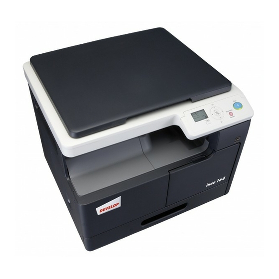
I. Outline of Installation Procedures for
ineo 184/ineo 164
Follow the notes below to install the machine and
the multi bypass tray.
Note:
• For the detailed installation procedures for the
multi bypass tray, see the Installation Manual,
and perform the procedures correctly.
• Once the power switch is turned on, do not turn
it off until the installation has been completed.
• When transporting or moving the machine,
assign adequate number of persons
(the machine mass: 23.5 kg/52 lb).
• This manual provides the illustrations of the
machine and the accessory parts that may be
slightly different in shape from yours. In that
case, instead of the illustrations, use the appear-
ance of yours to follow the installation proce-
dure. This does not cause any significant
change or problem with the procedure.
1BP0831302
INSTALLATION MANUAL
A0XXIXC001MA
/
Applied Machine:
II. Installation Space (unit: mm (inch))
ineo 184/ineo 164 + MB-503
928 (36-1/2)
783 (30-13/16)
607 (23-7/8)
570 (22-7/16)
III. Pre-installation Check Items
1. Install the machine at a horizontal and stable
place.
2. Be sure to use a power source of the voltage and
frequency indicated in the product specifications.
Ensure that the current carrying capacity of the
power outlet is at least equal to the current listed
in the product specifications.
3. Power the machine directly from a dedicated
power outlet. (Do not use an extension cord.)
4. Do not plug or unplug the power cord with wet or
dirty hands, otherwise you may get an electric
shock.
5. Avoid a hot and humid environment, or a place
exposed to direct sunlight.
6. Avoid a dusty location, or a place near volatile
and flammable substances.
7. Avoid a poorly ventilated place.
E-1
/
200
530 (20-7/8)
(8)
927 (36-1/2)
A0XXIXC002MA
A0XX-9635-01
Advertisement
Table of Contents

Related Manuals for Develop INEO 184


Summary of Contents for Develop INEO 184
- Page 1 © DEVELOP GmbH Applied Machine: I. Outline of Installation Procedures for II. Installation Space (unit: mm (inch)) ineo 184/ineo 164 ineo 184/ineo 164 + MB-503 928 (36-1/2) Follow the notes below to install the machine and 783 (30-13/16) the multi bypass tray.
- Page 2 IV. Accessory Parts VI. Removing Protective Tape, Packaging Materials and Imaging Unit Name Q’ty 1. Remove pieces of protective tape and packaging 1. User’s Guide 1 set materials. 2. Installation Manual (this manual) 3. Developer 4. Power Cord 5. Power Cord Instruction* 6.
- Page 3 4. Unscrew the screws shown in the illustration to 9. Slide out the drawer and remove the developer remove the imaging unit (two screws). and cushioning material. Note: • Do not touch or scratch the PC drum. Developer • Cover the imaging unit, which has been removed, with a protective cloth or similar mate- rial.
- Page 4 VII. Loading the Developer 3. Remove the developing unit cover (three screws). 1. While pressing the connector tabs, push out the connector from the imaging unit. A11UIXC014MA Tabs A0XXIXC040MA 4. Ready a packet of the developer and cut off one corner of the aluminum packet with scissors.
- Page 5 7. Install the front of the PC drum unit first, and then 10. Plug the connector, and then attach the cover the rear part. Then, secure the screws (five (one screw). screws). Note: • Do not open the lower part wide, otherwise the charger may drop.
- Page 6 IX. Installing the Toner Bottle Note: A toner bottle is not shipped with your machine. Purchase one that is separately available. 1. Shake the toner bottle well about five times in the vertical direction. Then, turn it over and repeat the same procedure.
Need help?
Do you have a question about the INEO 184 and is the answer not in the manual?
Questions and answers