ICC ETH-1000 Instruction Manual
Multiprotocol ethernet/ rs-485 gateway
Hide thumbs
Also See for ETH-1000:
- Instruction manual (76 pages) ,
- Installation manual (54 pages) ,
- Quick start manual (10 pages)

Related Manuals for ICC ETH-1000


Summary of Contents for ICC ETH-1000
- Page 1 Instruction Manual INDUSTRIAL CONTROL COMMUNICATIONS, INC. ETH-1000 Multiprotocol Ethernet / RS-485 Gateway January 15, 2012 ICC #10724 © 2012 Industrial Control Communications, Inc.
- Page 2 ETH-1000 User's Manual Part Number 10724 Printed in U.S.A. ©2012 Industrial Control Communications, Inc. All rights reserved OTICE SERS Industrial Control Communications, Inc. reserves the right to make changes and improvements to its products without providing notice. Industrial Control Communications, Inc. shall not be liable for technical or editorial...
- Page 3 PPLICABLE IRMWARE Main Processor: Modbus – BACnet Firmware Version 2.300 Metasys – Toshiba Firmware Version 2.200 Sullair – Chillgard Firmware Version 2.400 FLN – Basys Firmware Version 2.400 DMX-512 – M-Bus Firmware Version 2.300 AIN – PDNP Firmware Version 2.300 Coprocessor: Ethernet Multiple V2.320...
-
Page 4: Operating Environment
Usage Precautions Operating Environment • Please use the interface only when the ambient temperature of the environment into which the unit is installed is within the following specified temperature limits: -10 ∼ +50°C (+14 ∼ +122°F) Operation: -40 ∼ +85°C (-40 ∼ +185°F) Storage: •... -
Page 5: Table Of Contents
TABLE OF CONTENTS Introduction ................10 Features ..................11 Gateway Concepts ..............13 Precautions and Specifications ..........15 Installation Precautions ................. 15 Maintenance Precautions ..............16 Inspection ....................16 Maintenance and Inspection Procedure ..........16 Storage ....................17 Warranty ....................17 Disposal .................... - Page 6 8.5.1 Description of Common Fields ............32 8.5.2 Viewing the Status of a Service Object .......... 34 General Object Editing Options ............. 34 Ethernet Protocol Configuration ............36 8.7.1 Ethernet Configuration Subtab ............36 8.7.2 BACnet /IP Client ................37 8.7.3 BACnet/IP Server ................
- Page 7 10.2 Authentication ..................159 10.3 Navigation Menu Tree ................. 160 10.4 Activity Window ................... 160 10.5 Monitor Menu ..................160 10.5.1 Activity Indicator ................160 10.5.2 Database ..................161 10.6 MELSEC/SLMP Client Menu .............. 162 10.6.1 MELSEC Client Enable ..............162 10.6.2 Connection Object Configuration ..........
- Page 8 10.13 MELSEC/SLMP Server Menu ............. 176 10.13.1 MELSEC Server Enable .............. 176 10.13.2 TCP Port ..................176 10.13.3 Timeout Time Setting ..............176 10.13.4 Submitting Changes ..............177 10.14 Modbus/TCP Server Menu ..............178 10.14.1 Modbus/TCP Server Enable ............178 10.14.2 Timeout Time Setting ..............
- Page 9 11.3.4 BBMD ..................205 11.4 TCS Basys Master ................206 11.4.1 Overview ..................206 11.4.2 Basys Service Objects ..............206 11.4.3 Read-Only Monitoring Variables ..........206 11.4.4 Holiday Scheduling Parameters ........... 206 11.4.5 Parameter Scaling ............... 206 11.5 Chillgard Monitor ................. 208 11.5.1 Overview ..................
- Page 10 11.15.1 Overview ..................265 11.15.2 Toshiba Service Objects .............. 266 11.15.3 Parameter Mapping ..............266 12. Troubleshooting ............... 267 13. Appendix A: Database Endianness ........269 13.1 Ex: Modbus - Profibus ................. 271 13.2 Ex: Modbus - DeviceNet ..............272 13.3 Ex: BACnet - DeviceNet ..............
-
Page 11: Introduction
1. Introduction Congratulations on your purchase of the ICC ETH-1000 Multiprotocol Ethernet Communications Gateway. This gateway allows information to be transferred seamlessly between various industrial Ethernet networks and one of several RS- 485-based networks. In addition to the supported fieldbus protocols, the gateway hosts a USB interface for configuring the gateway via a PC. -
Page 12: Features
2. Features Supported Protocols The gateway currently provides support for the following Ethernet protocols: • BACnet/IP Client • BACnet/IP Server • BBMD (BACnet/IP broadcast management device) • CSP (also known as PCCC or Allen Bradley Ethernet) Client • CSP Server •... - Page 13 The gateway can be connected to a PC via a USB mini type-B cable. This simultaneously supplies power while providing the ability to configure the gateway, monitor data, and update firmware on the device using the ICC Gateway Configuration Utility. Refer to section 8.1 for more information.
-
Page 14: Gateway Concepts
3. Gateway Concepts The ETH-1000 is a member of the Millennium Series communication gateways. Members of this family are designed to provide a uniform interface, configuration and application experience. This commonality reduces the user’s learning curve, reducing commissioning time while simplifying support. All Millennium Series gateways are configured using the ICC Gateway Configuration Utility. - Page 15 ICC Gateway Configuration Utility’s Monitor tab when connected via USB to a PC. The ability to interact with the database is also available via the embedded web server.
-
Page 16: Precautions And Specifications
4. Precautions and Specifications Rotating shafts and electrical equipment can be hazardous. Installation, operation, and maintenance of the gateway shall be performed by Qualified Personnel only. Qualified Personnel shall be: • Familiar with the construction and function of the gateway, the equipment being driven, and the hazards involved. -
Page 17: Maintenance Precautions
4.2 Maintenance Precautions • Do Not attempt to disassemble, modify, or repair the gateway. Contact your ICC sales representative for repair or service information. • If the gateway should emit smoke or an unusual odor or sound, turn the power off immediately. -
Page 18: Storage
4.6 Warranty This gateway is covered under warranty by ICC, Inc. for a period of 12 months from the date of installation, but not to exceed 18 months from the date of shipment from the factory. For further warranty or service information, please contact Industrial Control Communications, Inc. -
Page 19: Gateway Overview
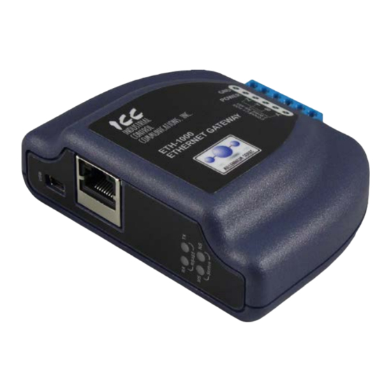
5. Gateway Overview MAC ID (on bottom) Ethernet activity LED (green) Ethernet link LED (amber) USB connector Shielded RJ45 Ethernet jack RS-485 TX and RX LEDs Module Status (MS) and Network Status (NS) LEDs Gateway Overview (Front) Power terminals RS-485 terminals Chassis GND Gateway Overview (Back) -
Page 20: Power Supply Electrical Interface
Voltage rating ......7 - 24VDC Minimum Current rating ..150mA (@24VDC) • ICC offers an optional 120VAC/12VDC power supply (ICC part number 10755) that can be used to power the gateway from a standard wall outlet. • The power supply must be connected to the gateway’s terminal block at terminals TB:5 (POWER) and TB:6 (GND) as highlighted in Figure 1. -
Page 21: Port Electrical Interface
100BASE-TX. Mode B power transmission, therefore, requires the use of a full 4-pair Ethernet cable. The gateway enumerates itself as a power level class 0 device (12.95W max. indicated consumption). The use of PoE endspan (“PoE switch”) or midspan (“power injector”) power sourcing equipment (PSE) provides for the ability to power the gateway without the necessity of connecting a dedicated power supply to the power supply terminal block. - Page 22 Figure 3 highlights the terminals on the gateway’s terminal block that are specific to RS-485 connections. Figure 3: Terminal Block RS-485 Connections...
-
Page 23: Installation
6. Installation The gateway’s installation procedure will vary slightly depending on the mounting method used. Before mounting the gateway, install the 4 black rubber feet (Figure 4) onto the bottom of the enclosure. Figure 4: Rubber Feet 6.1 Mounting the Gateway The gateway may be mounted on a panel, a wall or a DIN rail. -
Page 24: Din Rail Mounting
6.1.2 DIN Rail Mounting The DIN rail adapter (Figure 6) can clip onto 35mm and G-type rails. To mount the gateway to a DIN rail, clip the DIN rail adapter onto the DIN rail and mount the gateway on the screws (the screws should already be seated into the adapter at the proper height). -
Page 25: Wiring Connections
6.2 Wiring Connections Note that in order to power the unit, a power supply must also be installed. Refer to sections 5.1 and 5.2 for more information. Mount the unit via the desired method (refer to section 6.1). Connect the various networks to their respective plugs/terminal blocks. Ensure that any wires are fully seated into their respective terminal blocks, and route the network cables such that they are located well away from any electrical noise sources, such as adjustable-speed drive input power or... -
Page 26: Led Indicators
7. LED Indicators The gateway contains several different LED indicators, each of which conveys important information about the status of the unit and connected networks. These LEDs and their functions are summarized here. 7.1 Module/Network Status The gateway has two dichromatic, stacked LEDs to indicate the status of the module (MS) and the status of the Ethernet/IP network server driver (NS). -
Page 27: Network Status
7.2 RS-485 Network Status The gateway has one red and one green LED to indicate the status of the RS- 485 network. Green (TX) LED ..Lights when the gateway is transmitting data on the RS-485 port. Red (RX) LED ..Lights when the gateway is receiving data on the RS-485 port. -
Page 28: Configuration Concepts
PC. The gateway is configured by the ICC Gateway Configuration Utility PC application. For information on how to install the utility, refer to the ICC Gateway Configuration Utility User’s Manual. The following will briefly describe how to configure the gateway using the configuration utility. -
Page 29: Finder Tab
ICC Gateway Configuration Utility User’s Manual. 8.2 Finder Tab The Finder tab of the configuration utility discovers all ICC communication devices on the current Ethernet subnet, regardless of whether or not their network parameters are currently compatible with the subnet upon which they reside. - Page 30 Save IP Settings Saves the IP settings configured in the IP Settings group to the gateway. This will open a dialog box which prompts for a password to save the changes. Enter the case-sensitive system password (default is “icc”), then click Submit.
-
Page 31: Timeout Configuration Tab
Reboot Device Opens a dialog box which prompts for a password to reboot the device. Enter the case-sensitive system password (default is “icc”), then click Reboot. The reboot cycle has completed when the displayed status changes from “Rebooting” to “Ready” (note that this may require 20s or more to complete.) Clicking Close will then close the dialog box and cause the discovery utility to automatically rescan the network. -
Page 32: Port Configuration Tabs Protocol Selection Group
16-bit, or 32-bit value is written to the corresponding address(es). The following describes the configurable fields of a timeout object: Database Addr This field is the starting address in the database where the first data element of this timeout object will begin. Depending on the designated Data Type, the maximum allowable database address is 4095, 4094, or 4092 for 8-bit, 16-bit, or 32-bit sized objects, respectively. -
Page 33: Service Object Configuration
Timeout For master/client protocols, enter the request timeout in milliseconds. This setting is the maximum amount of time that the gateway will wait for a response from a remote device after sending a request. For slave/server protocols, this value is the maximum amount of time the protocol driver will wait in between received packets before triggering a timeout event (for network loss detection). - Page 34 Description This field is a description of the service object. It is not used by the gateway, but serves as a reference for the user. Destination Address This field is the network node address of the device that the gateway will send a request to.
-
Page 35: Viewing The Status Of A Service Object
Function Codes This field allows you to select which function code to use for a read or write. You may also specify a read-only or a write-only service object by unchecking the checkbox next to the write or the read function, respectively. Note that some protocols only support one read and one write function code. - Page 36 Updating an Object To update an object, select the object’s entry in the object window, make any required changes, and then click the Update button. Copying an Object To copy an object, select the entry you wish to copy in the object window, make any required changes, and then click the Create button.
-
Page 37: Ethernet Protocol Configuration
FTP session is initiated, or when a configuration change is performed via the Finder tab. Contact ICC for assistance if you have forgotten your customized credentials. -
Page 38: Bacnet /Ip Client
8.7.2 BACnet /IP Client To configure the BACnet/IP client, click on the Ethernet Configuration tab, check BACnet/IP Client in the protocol dropdown menu to enable the driver, and then click on the BACnet/IP Client subtab. The gateway can read and write the present value property of BACnet objects hosted by other devices on the network. - Page 39 Description This field is a description of the service object. It is not used on the gateway, but serves as a reference for the user. Enter a string of between 1 and 18 characters in length. Dest Dev Inst (“Destination Device Instance”) This field is the destination device instance of the BACnet device the gateway should send requests to for this service object.
- Page 40 Note that the multiplier, coupled with the data type, imposes range limitations on the network data value. For example, if the data type is 8-bit and the multiplier is 0.5, then the network data can have values only up to 127 (since 255 is the maximum value that can be stored in 8 bits).
-
Page 41: Bacnet/Ip Server
8.7.3 BACnet/IP Server To configure the BACnet/IP server, click on the Ethernet Configuration tab, check BACnet/IP Server in the protocol dropdown menu to enable the driver, and then click on the BACnet/IP Server subtab. The BACnet/IP server can host a wide variety of user-defined BACnet objects. Up to 200 objects can be configured. - Page 42 A note for analog objects: Depending on the designated Data Type, the maximum allowable database address is 4095, 4094, or 4092 for 8-bit, 16-bit, or 32-bit sized objects, respectively. Multiplier Applies to analog objects only. This field is the amount that associated network values are scaled by prior to being stored into the database or after being retrieved from the database.
- Page 43 Active Text Applies to binary objects only. This field specifies the description of the object’s “active” state. Enter a string of up to 8 characters in length. This field is optional and may be left blank. Inactive Text Applies to binary objects only. This field specifies the description of the object’s “inactive”...
-
Page 44: Bbmd
8.7.4 BBMD Currently, the BBMD is only configurable via the embedded web page. Refer to section 10.11. -
Page 45: Ethernet/Ip Client
8.7.5 EtherNet/IP Client The EtherNet/IP client protocol can be used to access information on EtherNet/IP and CSP server devices which support class 1 I/O messaging and class 3 explicit messaging. Similar to other master/client protocol drivers on the gateway, the EtherNet/IP client driver uses service objects to produce and consume data and to issue explicit read and write requests to the server device. - Page 46 Logix PLC produced tag. Before configuring the Produced Tag message type, it is suggested that users read the ICC whitepaper titled “Accessing Data on a Logix PLC with the ICC ETH-1000 Ethernet Gateway”, which can be found in the documents section at http://www.iccdesigns.com. All other selections indicate a specific type of class 3 explicit messaging.
- Page 47 retrieved from the gateway’s database starting at this address. Enter a value between 0 and 4095 (0x0 – 0xFFF). Pro Data Size (“Produced Data Size”) This field defines the number of bytes to produce (send to the server device). Enter a value of 0 or larger. Con Start Addr (“Consumed Data Start Address”) This field specifies the database address that the first consumed byte of data is mapped to.
- Page 48 The following fields apply to CIP Generic Message Types only Read Check Read to enable reading via the “get attribute single” service. Refer to the Triggering Mechanism to determine the specific behavior of read services. Write Check Write to enable writing via the “set attribute single” service. If writes are enabled, then when values encompassed by this service object change in the gateway’s database, these changes will be written down to the targeted device.
- Page 49 Write Check Write to enable writing via the “data table write” service. If writes are enabled, then when values encompassed by this service object change in the gateway’s database, these changes will be written down to the targeted device. Refer to the Triggering Mechanism to determine the specific behavior of write services.
- Page 50 Num Elements This field specifies the number of 16-bit elements to be accessed by this service object. Enter a value between 1 and 120 (0x1 – 0x78). This field specifies the tag name on the target device. Enter a string from 1 to 32 characters in length (note that tag names cannot contain spaces).
- Page 51 database. Upon retrieval from the database, the data is multiplied by the multiplier to produce a network value. Similarly, the network values are divided by the multiplier before being stored into the database Note that the multiplier, coupled with the data type, imposes range limitations on the network data value.
- Page 52 Con Data Size (“Consumed Data Size”) This field defines the number of bytes to consume (receive from the server device). Enter a value of 1 or more. This field is the Requested Packet Interval and is specified in units of milliseconds.
- Page 53 reestablish the class 1 connection to the server and resume regular I/O data production/consumption. For class 3 message types • If the Auto Trigger checkbox is checked, then the behavior of the service object will depend on the Read and Write function checkboxes: if the Read checkbox is checked, then the service object will continuously read from the remote server unless a pending Write exists.
-
Page 54: Ethernet/Ip Server
8.7.6 EtherNet/IP Server The EtherNet/IP server driver allows the gateway to participate in I/O messaging with other devices. It also supports the CSP server functionality without any additional configuration. While the database start addresses at which the produced and consumed data will map to are set via the configuration utility, the sizes of these exchanged data packets are determined by the client upon initial connection establishment. - Page 55 Produced Data Start Address This is the starting address in the database from which the gateway’s produced data will be taken. Enter an address between 0 and 4095 (0x0 – 0xFFF). Consumed Data Start Address This is the starting address in the database at which the gateway’s consumed data will be inserted.
-
Page 56: Csp Client
8.7.7 CSP Client CSP utilizes the Typed Read and Typed Write services and is configured using the EtherNet/IP client service object. Refer to section 8.7.5. -
Page 57: Csp Server
8.7.8 CSP Server To enable the CSP server, simply enable the EtherNet/IP server. No additional configuration is required. Refer to section 8.7.6. -
Page 58: Mitsubishi Melsec/Slmp Client
8.7.9 Mitsubishi MELSEC/SLMP Client The MELSEC client protocol can be used to access information on Mitsubishi PLCs and motion controllers which support the MELSEC server protocol using 3E and 1E frames. The MELSEC client protocol also supports SLMP (Seamless Message Protocol) to communicate to CC-Link IE Field networks via an Ethernet adapter that supports the SLMP server protocol using 3E frames. - Page 59 connection object, which improves performance by allowing these service objects to be processed in parallel.
- Page 60 Figure 10: MELSEC Client Concept...
- Page 61 To configure the MELSEC client, click on the Ethernet Configuration tab, check MELSEC Client in the protocol dropdown menu to enable the driver, and then click on the MELSEC subtab. This section will discuss how to configure the MELSEC client. Scan Rate This is the time in milliseconds the device will wait between sending requests.
- Page 62 Description This field is a description of the service object. It is not used on the gateway, but serves as a reference for the user. Enter a string of up to 18 characters in length. Connection Select the desired connection object from this dropdown menu (refer to section 8.7.9.1).
- Page 63 Starting Point This field is the starting point in a device's range of points. Enter a value between 0 and 16777215 (0x0 – 0xFFFFFF). If the targeted server uses 1E frames and the Device Code or Code Value is set to a bit device, the starting point should be a multiple of 16.
-
Page 64: Mitsubishi Melsec/Slmp Server
8.7.10 Mitsubishi MELSEC/SLMP Server The MELSEC server simultaneously functions as a SLMP server with no special configuration. To configure the MELSEC/SLMP server, click on the Ethernet Configuration tab, check MELSEC Server in the “Protocol” dropdown menu to enable the driver, and then click on the MELSEC Server subtab. 8.7.10.1 Protocol Selection Group TCP Port The server TCP port must be specified before establishing any connections. -
Page 65: Modbus/Tcp Client
8.7.11 Modbus/TCP Client The Modbus/TCP client driver can be used to access information on any device which supports the Modbus/TCP server protocol. This driver also supports the 32-bit extension to the Modbus standard (commonly referred to as the “Enron/Daniel” extension). Similar to other master/client protocol drivers on the gateway, the Modbus/TCP client driver uses service objects to issue read and write requests to the Modbus/TCP server device. - Page 66 8.7.11.2 Service Object Configuration Group Up to 64 service objects can be created. Description This field is a description of the service object. It is not used on the gateway, but serves as a reference for the user. Enter a string of up to 18 characters in length. Connection Select the desired connection object from this dropdown menu (refer to section 8.7.11.1).
- Page 67 Multiplier Applies to register types only. This field is the amount that associated network values are scaled by prior to being stored into the database or after being retrieved from the database. Upon retrieval from the database, raw data is multiplied by the multiplier to produce a network value.
- Page 68 Word-Size Reg Enable Word-Size Reg if each target register is 16-bits wide, but two 16-bit registers comprise one 32-bit value. If not enabled, each of the target registers is assumed to be 32-bits wide. Note that when Word-Size Reg is enabled, the Num Regs field name changes to Num Reg Pairs, indicating the number of pairs of 16-bit wide registers to address.
-
Page 69: Modbus/Tcp Server
Before enabling this timer, therefore, it is suggested that users read the ICC whitepaper titled “A Discussion of Modbus/TCP Server-Side Timeout Processing”, which can be found in the documents section at http://www.iccdesigns.com. - Page 70 Num Regs This field is the number of registers to remap. Enter a value of 1 or more. Database Addr This field is the database address where the remapping begins. Enter a value between 0 and 4094 (0x0 – 0xFFE). Register Type Select the appropriate register type(s) for the register remap.
- Page 71 registers” field will be interpreted as the number of 32-bit registers to be transferred. Data Type This field specifies how many bytes are used to store data for each register (or register pair), as well as whether the internal value should be treated as signed or unsigned when converted to a floating point number for transmission over the network.
-
Page 72: Profinet Io
8.7.13 PROFINET IO The PROFINET IO driver allows the gateway to participate in cyclic data exchange with a PROFINET controller. While the database start addresses at which the produced and consumed data will map to are set via the configuration utility, the sizes of these exchanged data packets are determined by the controller upon initial connection establishment. -
Page 73: Protocol Configuration
The following section describes how to configure the RS-485 protocols on the gateway with the configuration utility. For more details on how to use the configuration utility, refer to the ICC Gateway Configuration Utility User’s Manual. 8.8.1 A.O. Smith AIN Slave A.O. -
Page 74: Configuration Example
Configure the Ethernet port using the above requirements • Connect the gateway to the PC via a USB mini type-B cable. • Open the configuration utility and select the ETH-1000 (see section 8.1 for more information on selecting a device). • Click on the Ethernet Configuration subtab. - Page 75 • Click Use a static IP address and enter the IP address settings that your BAS is configured to communicate with. • Check the checkbox next to BACnet/IP Server in the Protocol dropdown menu and then click on the BACnet/IP subtab. •...
- Page 76 • Enter “5.12” for the Multiplier since these values are scaled by 512 on the water heater and we would like to preserve 2 decimal places. • Click Create. Create one service object to monitor the controlling temperature. • Enter “0” into the Block Num field. •...
- Page 77 Note that the database endianness is arbitrary in this example, as both protocols will access the database uniformly regardless of whether big or little endian storage is selected.
-
Page 78: Smith Pdnp Master
8.8.2 A.O. Smith PDNP Master A.O. Smith PDNP (Proprietary Device Network Protocol) Master can be configured on the RS-485 port by selecting AO Smith PDNP Master from the protocol dropdown menu. The PDNP Master protocol uses service objects to make requests. For more information on service objects, refer to section 8.5. Each parameter in a service object is mapped to 2 bytes in the database (the data size is fixed at 16-bit, as this is the native data size of PDNP parameters). - Page 79 Database Addr This field defines the database address where the first parameter of this service object will be mapped. Enter a value between 0 and 4094. Note that the configuration utility will not allow entry of a starting database address that will cause the service object to run past the end of the database.
- Page 80 • Open the configuration utility and select the ETH-1000 (see section 8.1 for more information on selecting a device). • Click on the Ethernet Configuration subtab. • Click Use a static IP address and enter the IP address settings that your BAS is configured to communicate with.
- Page 81 • Enter “5.12” for the Multiplier since these values are scaled by 512 on the boiler and we would like to preserve 2 decimal places. • Click Create. Create a service object to control the operating setpoint. • Enter the address of the boiler into the Dest Address field. •...
-
Page 82: Bacnet Ms/Tp Client
8.8.3 BACnet MS/TP Client BACnet MS/TP Client can be configured on the RS-485 port of the gateway by selecting BACnet MS/TP Client from the protocol dropdown menu. The gateway can read and write the present value property of BACnet objects hosted by other devices on the network. - Page 83 Max Master This field is the highest allowable address for MS/TP master nodes on the network. Any address higher than this will not receive the token from the gateway. Enter a value between 0 and 127. Note that this value must be greater than or equal to the configured Address for the gateway.
- Page 84 Dest Address Note that this field is available only when the Use Static Device Binding checkbox is checked. This field is used to manually define the address of the BACnet device that the gateway should target for this service object. Enter a value between 0 and 127.
- Page 85 Configure the Ethernet port using the above requirements • Connect the gateway to the PC via a USB mini type-B cable. • Open the configuration utility and select the ETH-1000 (see section 8.1 for more information on selecting a device). • Click on the Ethernet Configuration subtab.
- Page 86 • Enter “401” into the Instance field. • Enter “0” into the Database Addr field (the addresses for all BACnet/IP objects are arbitrary at this point, but must match the BACnet MS/TP configuration which will be completed later.) • Select 16-bit Unsigned from the Data Type dropdown. •...
- Page 87 • Enter “0x01” into the Bitmask field (this maps the binary output to the least-significant bit of the byte at database address 300.) • Click Create. For the second binary output, enter the following: • Select Binary Output from the Type selection group. •...
- Page 88 We can also create a single service object for both binary outputs • Select Binary Output from the Type selection group. • Enter the device instance of the drive in the Dest Dev Inst field. • Enter “1670” into the Start Inst field. •...
-
Page 89: Bacnet Ms/Tp Server
8.8.4 BACnet MS/TP Server BACnet MS/TP Server can be configured on the RS-485 port of the gateway by selecting BACnet MS/TP Server from the protocol dropdown menu. The BACnet MS/TP server can host a wide variety of user-defined BACnet objects. Whenever the BACnet MS/TP server is enabled, the BACnet device object is always present and must be properly configured. - Page 90 with address 0, ending with a device with a configurable Max Master field at the highest address. Then set that device’s Max Master field to its address. This will prevent any unnecessary poll for master packets on the network and thereby maximize efficiency.
- Page 91 Units and enter the enumerated value (as defined by the BACnet Specification) in the Unit Value field. Bitmask Applies to binary objects only. This 8-bit field specifies which bit(s) in the byte designated by the Database Addr that the binary object will map to. This allows up to 8 binary objects to be simultaneously assigned to one database address (each binary object mapping to a single bit of that byte in the database).
- Page 92 Configure the Ethernet port using the above requirements • Connect the gateway to the PC via a USB mini type-B cable. • Open the configuration utility and select the ETH-1000 (see section 8.1 for more information on selecting a device). • Click on the Ethernet Configuration subtab.
- Page 93 • Create BACnet objects to map the data from the PLC into produced and consumed data blocks which will then be exchanged on the EtherNet/IP side of the gateway. The produced data will start at database address 0 and the consumed data will start at database address 100.
- Page 94 Create objects for floor 2’s command data For the first object, enter the following: • Select Analog Value from the Type selection group. • Enter “F2 Cmd Data 1” into the Object Name field. • Enter “2003” into the Instance field. •...
- Page 95 Where are the monitor and command values? BACnet Object EtherNet/IP Byte Produced Data Byte 1 – Low byte Produced Data Byte 2 – Middle byte Floor 1 Monitor Data 1 (AV1000) Produced Data Byte 3 – High byte Produced Data Byte 4 – Upper byte Produced Data Byte 5 –...
- Page 96 BACnet Object EtherNet/IP Byte Consumed Data Byte 9 – Low byte Consumed Data Byte 10 – Middle byte Floor 1 Command Data 3 (AV1005) Consumed Data Byte 11 – High byte Consumed Data Byte 12 – Upper byte Consumed Data Byte 13 – Low byte Consumed Data Byte 14 –...
-
Page 97: Tcs Basys Master
8.8.5 TCS Basys Master TCS Basys Master can be configured on the RS-485 port by selecting Basys Master from the protocol dropdown menu. The TCS Basys Master protocol uses service objects to make requests. For more information on service objects, refer to section 8.5. - Page 98 Num Positions This field defines the number of positions associated with this service object. Enter a value between 1 and 16. Database Addr This field defines the database address where the first parameter of this service object will be mapped. Enter a value between 0 and 4094. Note that the configuration utility will not allow entry of a starting database address that will cause the service object to run past the end of the database.
- Page 99 Configure the Ethernet port using the above requirements • Connect the gateway to the PC via a USB mini type-B cable. • Open the configuration utility and select the ETH-1000 (see section 8.1 for more information on selecting a device). • Click on the Ethernet Configuration subtab.
- Page 100 • Select 16-bit Unsigned from the Data Type dropdown menu. • Enter “1” into the Multiplier field. • Select Fahrenheit (64) from the Units dropdown menu. • Click Create. Repeat these steps for the other three temperature points, increasing the Instance by 1, and Database Addr by 2 each time. Create an object for outdoor heat enable Enter the following: •...
- Page 101 • Select “’L’ \ ‘l’” from the function code drop-down box. • Because the room temperature ranges from -40 to 160 and the raw data values received from the thermostat are 0 to 255, enter “1.275” for the Multiplier and “-40” for the Offset.
- Page 102 Where are the monitor and command values? Database Thermostat Parameter BACnet Object Addresses 0 & 1 Room Temperature Analog Input 0 2 & 3 Outdoor Air Temperature Analog Input 1 4 & 5 Heating Setpoint Analog Input 2 6 & 7 Cooling Setpoint Analog Input 3 Outdoor Heating Enable...
-
Page 103: Master
Configure the Ethernet port using the above requirements • Connect the gateway to the PC via a USB mini type-B cable. • Open the configuration utility and select the ETH-1000 (see section 8.1 for more information on selecting a device). • Click on the Ethernet Configuration subtab. - Page 104 Configure the RS-485 port using the above requirements • Click on the RS-485 Configuration tab. • Select DMX-512 Master from the protocol dropdown menu. • Enter “0” for the Database Start Address. • Enter “8” for the Num Channels. Finishing Up •...
-
Page 105: Slave
8.8.7 DMX-512 Slave To configure the gateway for DMX-512 Slave, click on the RS-485 Configuration tab and select DMX-512 Slave in the protocol dropdown menu. The DMX-512 Slave configuration consists of assigning database bytes to channel numbers that the gateway will occupy in the DMX universe. Each byte in the database corresponds to one channel in the DMX packet. - Page 106 • Open the configuration utility and select the ETH-1000 (see section 8.1 for more information on selecting a device). • Click on the Ethernet Configuration subtab. • Click Use a static IP address and enter an IP address setting compatible with the servo motor’s IP address settings.
- Page 107 Where are the control values? Database Servo Parameter Modbus Register Address Channel X (Coarse Adjustment) Register 100 (Upper Byte) X (Fine Adjustment) Register 100 (Lower Byte) Y (Coarse Adjustment) Register 101 (Upper Byte) Y (Fine Adjustment) Register 101 (Lower Byte) Note that the database endianness is assumed to be big endian in this example.
-
Page 108: M-Bus Master
8.8.8 M-Bus Master M-Bus Master can be configured on the RS-485 port by selecting M-Bus Master from the protocol dropdown menu. The M-Bus Master protocol uses service objects to make requests. For more information on service objects, refer to section 8.5. Each service object configures the gateway to match and store data from a slave’s Request User Data response for read requests and to Send User Data to the slave for write requests. - Page 109 Database Addr This field defines the database address where the data of this service object will be mapped. Enter a value between 0 and 4095. Note that the configuration utility will not allow entry of a starting database address that will cause the service object to run past the end of the database.
- Page 110 8.8.8.2.1 Data Information Block (DIB) Configuration Manually Enter Bytes Enable This checkbox toggles between manually entering hex bytes for the DIB and configuring the DIB using the provided dropdowns and edit boxes. DIB Bytes This field allows the user to enter hex bytes to be used for the DIB, when enabled.
- Page 111 Configure the Ethernet port using the above requirements • Connect the gateway to the PC via a USB mini type-B cable. • Open the configuration utility and select the ETH-1000 (see section 8.1 for more information on selecting a device). • Click on the Ethernet Configuration subtab.
- Page 112 • Enter “4” into the Database Addr field. • Select 32-bit Signed from the Data Type dropdown menu. • Enter “1” into the Multiplier field. • Select Celsius (62) from the Units dropdown menu. • Click Create. For the return temperature object, enter the following: •...
- Page 113 • Uncheck Manually Enter Bytes in the Data Information Block (DIB) group and select No Data / Auto Detect from the Data Field dropdown. • Uncheck Manually Enter Bytes in the Value Information Block (VIB) group and select Flow Temperature [°C] from the Unit and Multiplier dropdown.
-
Page 114: Metasys N2 Master
8.8.9 Metasys N2 Master Metasys N2 Master can be configured on the RS-485 port by selecting Metasys Master from the protocol dropdown menu. The Metasys N2 Master protocol uses service objects to make requests. For more information on service objects, refer to section 8.5. - Page 115 Num Insts This field is the number of N2 objects in this service object. Enter a value of 1 or more. Database Addr This field is the database address where the first N2 object of this service object will be mapped. Enter a value between 0 and 4095 (0x0 – 0xFFF). Note that the configuration utility will not allow entry of a starting database address that will cause the service object to run past the end of the database.
- Page 116 Configure the Ethernet port using the above requirements • Connect the gateway to the PC via a USB mini type-B cable. • Open the configuration utility and select the ETH-1000 (see section 8.1 for more information on selecting a device). • Click on the Ethernet Configuration subtab.
- Page 117 • Click Create. Since the output voltage has a different multiplier than the other two analog inputs, it must be defined as a separate service object. • Select Analog Input from the Type selection group. • Enter the address of the drive into the Dest Address field. •...
- Page 118 Where are the monitor and command values? Database N2 Object Modbus Discrete / Register Address 0 & 1 Register 1 – lower 16 bits Output Frequency (Analog Input 1) 2 & 3 Register 2 – upper 16 bits 4 & 5 Register 3 –...
-
Page 119: Metasys N2 Slave
8.8.10 Metasys N2 Slave Johnson Controls Metasys N2 slave can be configured on the RS-485 port of the gateway by selecting Metasys N2 Slave from the protocol dropdown menu. The Metasys N2 slave driver can host a wide variety of user-defined N2 objects. This section will discuss how to configure the Metasys N2 driver. - Page 120 Database Addr This field is the database address where the Metasys object’s current value will reside. Enter a value between 0 and 4095 (0x0 – 0xFFF). A note for analog objects: Depending on the designated Data Type, the maximum allowable database address is 4095, 4094, or 4092 for 8-bit, 16-bit, or 32-bit sized objects, respectively.
- Page 121 Configure the Ethernet port using the above requirements • Connect the gateway to the PC via a USB mini type-B cable. • Open the configuration utility and select the ETH-1000 (see section 8.1 for more information on selecting a device). • Click on the Ethernet Configuration subtab.
- Page 122 • Click Create. Repeat these steps for the other two AO objects, increasing the Object Name by 1, Instance by 1, and Database Addr by 4 each time. Create input objects for floor 1’s command data For the first object, enter the following: •...
- Page 123 Create output objects for floor 3’s monitor data For the first object, enter the following: • Select Analog Output from the Type selection group. • Enter “F3 Mon Data 1” into the Object Name field. • Enter “7” into the Instance field. •...
- Page 124 Where are the monitor and command values? Metasys Object EtherNet/IP Byte Produced Data Byte 1 – Low byte Produced Data Byte 2 – Middle byte Floor 1 Monitor Data 1 (AO1) Produced Data Byte 3 – High byte Produced Data Byte 4 – Upper byte Produced Data Byte 5 –...
- Page 125 Metasys Object EtherNet/IP Byte Consumed Data Byte 9 – Low byte Consumed Data Byte 10 – Middle byte Floor 1 Command Data 3 (AI3) Consumed Data Byte 11 – High byte Consumed Data Byte 12 – Upper byte Consumed Data Byte 13 – Low byte Consumed Data Byte 14 –...
-
Page 126: Modbus Rtu Master
8.8.11 Modbus RTU Master To configure the gateway for Modbus RTU Master, click on the RS-485 Configuration tab and select Modbus RTU Master in the protocol dropdown menu. The Modbus RTU Master protocol uses service objects to make requests. For more information on service objects, refer to section 8.5. Each register (input or holding) in a service object is mapped to 2 bytes in the database (the data type is fixed at 16-bit). - Page 127 Dest Address This field indicates the destination address of the remote slave device on the network that will be accessed by this service object. Enter a value between 0 and 247. Note that address 0 is defined by Modbus as the broadcast address: if this address is used, the Read function checkbox must be unchecked, as attempts to read a service object targeting destination address 0 will invariably time out.
- Page 128 Write Enable and Function Code Selection Applies to holding register and coil status types only. Check Write to enable writing (when values encompassed by this service object change in the gateway’s database, these changes will be written down to the targeted slave). When writes are enabled, the desired write Function Code can be selected in the drop-down box.
- Page 129 2001 – 2100. Configure the Ethernet port using the above requirements • Connect the ETH-1000 to the PC via a USB mini type-B cable. • Open the configuration utility and select the ETH-1000 (see section 8.1 for more information on selecting a device).
- Page 130 • Check the Modbus/TCP Server checkbox in the Protocol dropdown menu, and then click on the Modbus/TCP subtab. • Because the desired register range (2001 – 2100) exceeds the default register access mapping of the database, we must create a register remap object to expose a portion of the database at the alternate register range: We can create a single register remap object to remap holding registers 2001 –...
-
Page 131: Modbus Rtu Slave
8.8.12 Modbus RTU Slave To configure the gateway for Modbus RTU Slave, click on the RS-485 Configuration tab and select Modbus RTU Slave in the protocol dropdown menu. By default, the gateway’s entire database is accessible via the register mapping discussed in section 11.12.2.2.2. 8.8.12.1 Protocol Selection Group Protocol Select Modbus RTU Slave from this dropdown menu. - Page 132 Type This group designates the Modbus register type(s) that this object will remap. Choose Holding Register and/or Input Register to assign which register type(s) to remap. Description This field is a description of the register remap object. It is not used on the gateway, but serves as a reference for the user.
- Page 133 Big Endian Enable Big Endian if the transmitted values are to be encoded in big-endian, 16- bit word order, i.e. the most significant 16-bit word is before the least significant 16-bit word. Word-Size Register Enable Word-Size Register if each target register is 16-bits wide, but two 16-bit registers are to comprise one 32-bit value.
- Page 134 Configure the Ethernet port using the above requirements • Connect the gateway to the PC via a USB mini type-B cable. • Open the configuration utility and select the ETH-1000 (see section 8.1 for more information on selecting a device). • Click on the Ethernet Configuration subtab.
- Page 135 Remap floor 3’s monitor data registers: • Enter “3000” into the Start Reg field. • Enter “3” into the Num Regs field. • Enter “12” into the Database Addr field. • Click Create. Remap floor 1’s command data registers: • Enter “3003”...
- Page 136 Where are the monitor and command values? Modbus Register EtherNet/IP Byte Floor 1 Monitor Data 1 Produced Data Byte 1 – Lower byte Produced Data Byte 2 – Upper byte (Register 1000) Floor 1 Monitor Data 2 Produced Data Byte 3 – Lower byte Produced Data Byte 4 –...
-
Page 137: Modbus Rtu Sniffer
8.8.13 Modbus RTU Sniffer To configure the gateway for Modbus RTU Sniffer, click on the RS-485 Configuration tab and select Modbus RTU Sniffer in the protocol dropdown menu. The Modbus RTU Sniffer driver is passive (listen only), and uses service objects to define what registers to log values for from the network traffic. - Page 138 broadcast messages will also be logged for that service object as well as requests targeted specifically at the defined destination address. Start Reg This field defines the starting register number for a range of registers associated with this service object. Enter a value between 1 and 65535. Num Regs This field defines the number of registers associated with this service object.
- Page 139 • Connect the gateway to the PC via a USB mini type-B cable. • Open the configuration utility and select the ETH-1000 (see section 8.1 for more information on selecting a device). Configure the RS-485 port using the above requirements •...
- Page 140 To monitor the drive’s frequency command, we must create a second service object for that register. • Select Holding Register from the Type selection. • Enter the address of the drive into the Dest Address field. • Enter “14” into the Start Reg field. •...
-
Page 141: Siemens Fln Slave
FLN Slave from the protocol dropdown menu. The Siemens FLN slave driver supports fully configurable FLN objects for the creation of new FLN applications. Because the FLN application must first be approved before use, an application number must be acquired through Siemens. Please contact ICC for configuration and registration instructions. -
Page 142: Sullair Supervisor Master
8.8.15 Sullair Supervisor Master To configure the gateway for Sullair Supervisor Master, click on the RS-485 Configuration tab and select Sullair Master in the protocol dropdown menu. The Sullair Master protocol uses service objects to make requests. For more information on service objects, refer to section 8.5. Except for display parameters, each parameter in a Sullair supervisor service object is mapped to 2 bytes in the database (the data size is fixed at 16-bit). - Page 143 Configure the gateway using the above requirements • Connect the gateway to the PC via a USB mini type-B cable. • Open the configuration utility and select the ETH-1000 (see section 8.1 for more information on selecting a device).
- Page 144 Configure the RS-485 port using the above requirements • Click on the RS-485 Configuration tab. • Select Sullair Master from the protocol dropdown menu. • Create Service Objects to read and write the desired parameters. Because the pressure and temperature parameters are located at contiguous indexes (107 –...
- Page 145 Where are the monitor and command values? Controller Parameter Database Address (Parameter Index) P1 (107) 0 & 1 P2 (108) 2 & 3 P3 (109) 4 & 5 P4 (110) 6 & 7 T1 (111) 8 & 9 T2 (112) 10 &...
-
Page 146: Toshiba Asd Master
8.8.16 Toshiba ASD Master To configure the gateway for Toshiba ASD Master, click on the RS-485 Configuration tab and select Toshiba ASD Master in the protocol dropdown menu. The Toshiba ASD Master protocol uses service objects to make requests. For more information on service objects, refer to section 8.5. Each parameter in a service object is mapped to 2 bytes in the database (the data size is fixed at 16- bit, as this is the native data size of Toshiba ASD parameters). - Page 147 unchecked, as attempts to read a service object targeting destination address 255 will invariably time out. Start Param This field defines the starting parameter number for a range of drive parameters associated with this service object. Enter a value between 0 and FF99. For example, the drive’s output frequency typically resides at parameter FE00.
- Page 148 Configure the Ethernet port using the above requirements • Connect the gateway to the PC via a USB mini type-B cable. • Open the configuration utility and select the ETH-1000 (see section 8.1 for more information on selecting a device). • Click on the Ethernet Configuration subtab.
- Page 149 • Enter “16” into the Consumed Data Start Address field. Configure the RS-485 port using the above requirements • Click on the RS-485 Configuration tab. • Select Toshiba ASD Master from the protocol dropdown menu. • Enter the Baud Rate and Parity settings to match that of the drive. •...
- Page 150 drive command registers (which exist only in RAM), either “P” or “W” will work fine: we will choose “P” from the dropdown menu. • Click Create. Finishing Up • Download the configuration to the gateway (see section 8.1 for more information on downloading a configuration to a device).
-
Page 151: Interacting With The Filesystem
9. Interacting With the Filesystem The gateway’s on-board filesystem is used to store files for use by the application firmware. Currently, the application firmware’s main use of the filesystem is to store XML-encoded configuration files that dictate the characteristics of the various protocols. -
Page 152: Initiating Ftp Via The Finder Tab
(Microsoft Internet Explorer) is configured as the default FTP application. An authentication dialog will appear (refer to Figure 11). Enter the currently- configured user name and case-sensitive password (defaults are “root” and “icc”, respectively), then click “Log On.” Figure 11: FTP Authentication The web browser will then display the filesystem’s contents (refer to Figure 12.) -
Page 153: Using Ftp With Windows Explorer
Figure 12: FTP Navigation with Internet Explorer 9.2 Using FTP with Windows Explorer To use FTP with Microsoft Windows Explorer, first open either “Windows Explorer” or “My Computer”. Refer to Figure 13. Please note that the indicated procedure, prompts and capabilities outlined here can vary depending on such factors as the installed operating... - Page 154 You will then be presented with an authentication dialog (refer to Figure 15.) The user name will already be filled-in. Enter the case-sensitive password (default is “icc”) and click “Log On.” Figure 15: FTP Authentication Windows Explorer will then display the filesystem’s contents (refer to Figure 16.) You can now perform normal file manipulation actions on the available files (cut, copy, paste, open, rename, drag-and-drop transfers etc.) in the same manner as...
-
Page 155: Using Ftp With A Windows Command Prompt
Once the command prompt opens, type “ftp” and the IP address of the target gateway. The FTP client will connect to the unit and then prompt for the username and case-sensitive password (defaults are “root” and “icc”, respectively). Upon successful entry of the authentication information, you will be presented with an “ftp>”... - Page 156 Figure 18: Listing Files with "ls" Command Figure 19: Copying a File from the Unit With "get" Command Figure 20: Copying a File to the Unit With "put" Command...
-
Page 157: Using Ftp With Core Ftp Le
Figure 21: Core FTP Site Manager Click on the “New Site” button, then enter a Site Name, IP Address, user name (default is “root”) and case-sensitive password (default is “icc”). The “Port”, “Timeout”, and “Retries” fields should already contain the default values. Click the “Connect”... - Page 158 Figure 22: Core FTP in "Connected" State...
-
Page 159: Embedded Web Server
10. Embedded Web Server 10.1 Overview In addition to the ability to configure the gateway over USB via the ICC Gateway Configuration Utility, all Ethernet drivers may also be configured through the gateway’s embedded web server (also known as an HTTP server). This dual- access capability allows users to access the gateway’s data in a graphical... -
Page 160: Authentication
Refer to Figure 24. Figure 24: Web Server Authentication The factory-default user name is “root”, and the password is “icc”. Note that the username and password are case-sensitive, and that once authenticated, the authentication will remain in effect from that point until all browser windows are closed. -
Page 161: Navigation Menu Tree
10.3 Navigation Menu Tree The web interface is structured as a navigation menu tree accessible on the left- hand side of the web page, where each menu contains information common to a specific feature or protocol. Refer to Figure 25. To change to a different configuration menu, just click on the title of the menu you wish to view. -
Page 162: Database
network problem: to reestablish communications, select “refresh” on your web browser. 10.5.2 Database The database displays the live values from the associated device's internal database. The alignment (byte, word or double word) and radix (hex or decimal) of the displayed data can be adjusted via the appropriate controls in the “Radix” and “Data Type”... -
Page 163: Melsec/Slmp Client Menu
10.6 MELSEC/SLMP Client Menu The MELSEC Client menu provides access to the same general configuration items accessible via the MELSEC Client subtab in the configuration utility. Refer to Figure 27. Figure 27: MELSEC Client Menu 10.6.1 MELSEC Client Enable Check to enable the MELSEC client driver. 10.6.2 Connection Object Configuration For more information regarding MELSEC connection object configuration, refer to section 8.7.9.1. -
Page 164: Submitting Changes
10.6.4 Submitting Changes Whenever the MELSEC client configuration has been changed, the “submit” button must be clicked in order to write these settings to the gateway’s filesystem. Note that because these configuration elements are read from the filesystem only when the gateway boots up, the act of submitting configuration changes will also reset the gateway. -
Page 165: Ethernet/Ip Client Menu
10.7 EtherNet/IP Client Menu The EtherNet/IP Client menu provides access to the same general configuration items accessible via the EtherNet/IP Client subtab in the configuration utility. Refer to Figure 28. Figure 28: EtherNet/IP Client Menu 10.7.1 EtherNet/IP Client Enable Check to enable the EtherNet/IP client driver. 10.7.2 Connection Object Configuration For more information regarding EtherNet/IP Client connection object configuration, refer to section 8.7.5.1. -
Page 166: Submitting Changes
10.7.4 Submitting Changes Whenever the EtherNet/IP client configuration has been changed, the “submit” button must be clicked in order to write these settings to the gateway’s filesystem. Note that because these configuration elements are read from the filesystem only when the gateway boots up, the act of submitting configuration changes will also reset the gateway. -
Page 167: Modbus/Tcp Client Menu
10.8 Modbus/TCP Client Menu The Modbus/TCP Client menu provides access to the same general configuration items accessible via the Modbus/TCP Client subtab in the configuration utility. Refer to Figure 29. Figure 29: Modbus/TCP Client Menu 10.8.1 Modbus/TCP Client Enable Check to enable the Modbus/TCP client driver. 10.8.2 Connection Object Configuration For more information regarding Modbus/TCP Client connection object configuration, refer to section 8.7.11.1. -
Page 168: Submitting Changes
10.8.4 Submitting Changes Whenever the Modbus/TCP client configuration has been changed, the “submit” button must be clicked in order to write these settings to the gateway’s filesystem. Note that because these configuration elements are read from the filesystem only when the gateway boots up, the act of submitting configuration changes will also reset the gateway. -
Page 169: Bacnet/Ip Client Menu
10.9 BACnet/IP Client Menu The BACnet/IP Client menu provides access to the same general configuration items accessible via the BACnet/IP Client subtab in the configuration utility. Refer to Figure 30. Figure 30: BACnet/IP Client Menu 10.9.1 BACnet/IP Client Enable Check to enable the BACnet/IP client driver. 10.9.2 Device Object Configuration For information regarding these fields, refer to section 8.7.2.1. -
Page 170: Submitting Changes
10.9.4 Submitting Changes Whenever the BACnet/IP client configuration has been changed, the “submit” button must be clicked in order to write these settings to the gateway’s filesystem. Note that because these configuration elements are read from the filesystem only when the gateway boots up, the act of submitting configuration changes will also reset the gateway. -
Page 171: Bacnet/Ip Server Menu
10.10 BACnet/IP Server Menu The BACnet/IP Server menu provides for the configuration of the gateway as a server on a BACnet/IP network. Refer to Figure 31. Figure 31: BACnet/IP Server Menu 10.10.1 BACnet/IP Server Enable Check to enable the BACnet/IP server driver. 10.10.2 Device Object Configuration For information regarding these fields, refer to section 8.7.3.1. -
Page 172: Submitting Changes
10.10.4 Submitting Changes The “submit” button must be clicked in order to write changed settings to the gateway’s filesystem. Note that because these configuration elements are read from the filesystem only when the gateway boots up, the act of submitting configuration changes will also reset the gateway. -
Page 173: Bbmd Menu
10.11 BBMD Menu The BBMD menu provides for the configuration of the gateway as a BBMD (BACnet/IP broadcast management device) on a BACnet/IP network. The BBMD function is needed when a BACnet/IP network spans over several IP subnets separated by IP routers. Refer to Figure 32. Figure 32: BBMD Server Menu 10.11.1 BBMD Enable Check to enable the BBMD driver. -
Page 174: Foreign Device Table (Fdt)
Distribution Mask: The default value is 255.255.255.255, also known as the 2- hop method. This ensures that packets can be successfully forwarded to the target BBMD, which in turn will broadcast the packet on its own local subnet. If it is necessary to change the default value, be sure to first check the capabilities of the router. -
Page 175: Ethernet/Ip Server Menu
10.12 EtherNet/IP Server Menu The EtherNet/IP Server menu provides access to the same general configuration items accessible via the EtherNet/IP Server subtab in the configuration utility. Refer to Figure 33. Figure 33: EtherNet/IP Server Menu 10.12.1 EtherNet/IP Enable Check to enable the EtherNet/IP server driver. 10.12.2 Run/Idle Flag Behavior For more information, refer to Run/Idle Flag Behavior in section 8.7.6.1. -
Page 176: Class 1 (I/O) Data Configuration
10.12.4 Class 1 (I/O) Data Configuration For more information, refer to Produced Data Start Address and Consumed Data Start Address in section 8.7.6.1. 10.12.5 Submitting Changes Whenever any of the EtherNet/IP server configuration elements have been changed, the “submit” button must be clicked in order to write these settings to the gateway’s filesystem. -
Page 177: Melsec/Slmp Server Menu
10.13 MELSEC/SLMP Server Menu The MELSEC Server menu provides access to the same general configuration items accessible via the MELSEC Server subtab in the configuration utility. Refer to Figure 34. Figure 34: MELSEC Server Menu 10.13.1 MELSEC Server Enable Check to enable the MELSEC server driver. 10.13.2 TCP Port For more information, refer to section 8.7.10.1. -
Page 178: Submitting Changes
10.13.4 Submitting Changes Whenever the MELSEC server configuration has been changed, the “submit” button must be clicked in order to write these settings to the gateway’s filesystem. Note that because these configuration elements are read from the filesystem only when the gateway boots up, the act of submitting configuration changes will also reset the gateway. -
Page 179: Modbus/Tcp Server Menu
10.14 Modbus/TCP Server Menu The Modbus/TCP Server menu provides access to the same general configuration items accessible via the Modbus/TCP subtab in the configuration utility. Refer to Figure 35. Figure 35: Modbus/TCP Server Menu 10.14.1 Modbus/TCP Server Enable Check to enable the Modbus/TCP server driver. 10.14.2 Timeout Time Setting For more information, refer to section 8.3.1. -
Page 180: Submitting Changes
10.14.4 Submitting Changes Whenever the Modbus/TCP server configuration has been changed, the “submit” button must be clicked in order to write these settings to the gateway’s filesystem. Note that because these configuration elements are read from the filesystem only when the gateway boots up, the act of submitting configuration changes will also reset the gateway. -
Page 181: Profinet Io Menu
10.15 PROFINET IO Menu The PROFINET IO menu provides access to the same general configuration items accessible via the PROFINET IO subtab in the configuration utility. Refer to Figure 36. Figure 36: PROFINET IO Menu 10.15.1 PROFINET IO Enable Check to enable the PROFINET IO driver. 10.15.2 Device Identification For more information, refer to Device Name in section 8.7.13.1. -
Page 182: Submitting Changes
10.15.4 Submitting Changes Whenever any of the PROFINET IO configuration elements have been changed, the “submit” button must be clicked in order to write these settings to the gateway’s filesystem. Note that because these configuration elements are read from the filesystem only when the gateway boots up, the act of submitting configuration changes will also reset the gateway. -
Page 183: Network Settings Menu
10.16 Network Settings Menu The network settings menu provides access to the same general Ethernet configuration items accessible via the Ethernet Configuration subtab in the configuration utility. Refer to Figure 37. Figure 37: Network Settings Menu 10.16.1 Authentication Refer to section 8.7.1.1. 10.16.2 Network Configuration Figure 38 shows the configuration items used to modify the IP address-related parameters. -
Page 184: Mac Address
Figure 38: Network Configuration 10.16.3 MAC Address Figure 39 shows the entry boxes that are used to view the unique MAC address of the gateway. Figure 39: MAC Address 10.16.4 Submitting Changes Whenever any of the network settings have been changed, the “submit” button must be clicked in order to write these settings to the gateway’s filesystem. -
Page 185: Alarm Menu
10.17 Alarm Menu The alarm menu provides a configurable mechanism by which the gateway can autonomously monitor any database address and send emails to up to four recipients when a certain condition is detected. The alarm conditions have both value and time constraints, and can be configured to retrigger at a fixed interval as long as the alarm condition continues to be satisfied. -
Page 186: Email Configuration
10.17.1 Email Configuration In order for an alarm trigger to successfully send a notification email, some network settings must first be configured properly (refer to Figure 41.) SMTP Authentication: Some email servers require that clients wishing to send emails first authenticate themselves. If the email server in use requires authentication, then enter the appropriate user name and password. -
Page 187: Alarm Configuration
When a test email transmission is initiated, completes successfully, or fails due to an error, the activity window (refer to section 10.4) will display appropriate messages such as those shown in Figure 42 and Figure Figure 42: Activity Window at Test Email Initiation Although the test email is sent immediately, note that due to internet... - Page 188 this address designates the database starting location for the multi-byte element to be evaluated. For multi-byte elements, whether this designated address represents the element’s high byte or low byte depends upon the current database endianness setting. Logical Comparison: Choose a comparison operator which will be used to compare the current value of the indicated “Data Size”...
-
Page 189: Submitting Changes
for this alarm unless the alarm condition is first evaluated as “false” (which resets the alarm), and then once again is triggered by a subsequent event. If this check box is checked, then as long as the alarm condition continues to be evaluated as “true”, subsequent email transmissions will be automatically retriggered every indicated number of minutes for a maximum of the indicated number of times. -
Page 190: Dashboard Menu
10.18 Dashboard Menu The Dashboard Menu provides access to a variety of gauges, meters and graphs that can be configured to provide an at-a-glance graphical overview of critical application variables in real-time. A total of 10 gauge windows are available (four at a time), and each gauge window can be configured to display any database value via one of six different gauge types. -
Page 191: Gauge Window Configuration
10.18.2 Gauge Window Configuration Each of the gauge windows can be independently configured to display database values with a variety of flexible configuration options. While the behavior and presentation may vary slightly depending on the specific gauge chosen, all of the gauges share the following common elements (refer to Figure 47 for an example): Gauge Selector: A drop-down selection box in the upper left-hand corner of the... - Page 192 The following is a summary of the different available gauge types: Gauge: Refer to Figure 47. This type of meter implements a rotary dial-type display format. The indicated value and units are shown numerically on the face of the gauge, and via the red indicator needle.
- Page 193 Pos/Neg Meter: Refer to Figure 50. Similar to the “meter” gauge, this type of meter also implements a common panel meter-type display format, but in this instance the indicated value can be positive or negative (two’s complement interpretation). Because the meter placard is always centered around zero, the “Min Value”...
-
Page 194: Submitting Changes
Gauge Usage Tip At times, it may be convenient to zoom in on a particular gauge or meter in order to more clearly see the indicator, or to fill the computer screen with a particular gauge’s image. This can be easily accomplished with the web browser’s Flash Player plug-in by right-clicking on the gauge and... -
Page 195: Timeout Menu
10.19 Timeout Menu The Timeout menu provides access to configuration items related to timeout processing. Refer to Figure 54. Figure 54: Timeout Menu 10.19.1 Timeout Object Configuration For detailed information regarding timeout configuration, refer to section 8.3. -
Page 196: Protocol-Specific Information
11. Protocol-Specific Information This section will discuss topics that are specific to each of the supported protocols. 11.1 A.O. Smith AIN Slave 11.1.1 Overview The gateway supports the A.O. Smith Advanced Internal Network (AIN) slave protocol on its RS-485 port. Some notes of interest are: •... -
Page 197: Smith Pdnp Master
11.2 A.O. Smith PDNP Master 11.2.1 Overview The gateway supports the A.O. Smith Proprietary Device Network (PDN) master protocol on its RS-485 port. This protocol is primarily used in A.O. Smith Boiler products. Some notes of interest are: • Requests are fully configurable through service objects. •... -
Page 198: Bacnet
V2.300 BACnet Protocol Revision: Product Description: The ETH-1000 is an Ethernet to RS-485 multiprotocol gateway. This product supports native BACnet, connecting directly to the IP and/or MS/TP LAN using baud rates of 4800, 9600, 19200, 38400, 57600, 76800, and 115200. The device can be configured as a BACnet/IP client and/or BACnet/IP server, BBMD, and MS/TP client and/or MS/TP server. - Page 199 Segmentation Capability: None Segmented requests supported Window Size ________ Segmented responses supported Window Size ________ Standard Object Types Supported: See “Object Types/Property Support Table” for object details. Data Link Layer Options: BACnet IP, (Annex J) BACnet IP, (Annex J), Foreign Device ISO 8802-3, Ethernet (Clause 7) ANSI/ATA 878.1, 2.5 Mb.
- Page 200 If this product is a communication gateway, describe the types of non-BACnet equipment/networks(s) that the gateway supports: Refer to Section 11 for other supported protocols. Datatypes Supported: The following table summarizes the datatypes that are accepted (in the case of a write property service) and returned (in the case of a read property service) when targeting the present value property of each supported object type.
- Page 201 Object Types/Property Support Table The following table summarizes the Object Types/Properties supported. Object Type Property Binary Binary Binary Analog Analog Analog Device Input Output Value Input Output Value Object Identifier Object Name Object Type System Status Vendor Name Vendor Identifier Model Name Firmware Revision App Software Revision...
-
Page 202: Bacnet/Ip And Bacnet Ms/Tp Client
11.3.2 BACnet/IP and BACnet MS/TP Client 11.3.2.1 Overview The gateway supports BACnet IP client on its Ethernet port and BACnet MS/TP client on its RS-485 port. Some notes of interest are: • The gateway supports reading and writing the present value property of BACnet objects in devices on the network. - Page 203 request will respond with an I-Am response, informing the client of what network address its device instance is associated with. By default, the gateway will use dynamic device binding if a service object is not configured to use static device binding.
-
Page 204: Bacnet/Ip And Bacnet Ms/Tp Server
11.3.3 BACnet/IP and BACnet MS/TP Server 11.3.3.1 Overview The gateway supports BACnet IP server on its Ethernet port and BACnet MS/TP server on its RS-485 port. Some notes of interest are: • Fully configurable BACnet objects. • Supported BACnet objects include: Analog Input Analog Output Analog Value... - Page 205 Reinitialize Device This service is used to reset the device. The gateway does not distinguish between a warm and cold restart. This service is password protected. To successfully reset the gateway, “icc” must be used as the password.
-
Page 206: Bbmd
11.3.4 BBMD 11.3.4.1 Overview The gateway supports BBMD (BACnet/IP broadcast management device) functionality on its Ethernet port for BACnet/IP. Some notes of interest are: • Supports up to 32 BDT entries. • Supports up to 32 FDT entries • Does not register as a foreign device 11.3.4.2 Supported BBMD Services This section details the BBMD services that are supported: Write Broadcast Distribution Table... -
Page 207: Tcs Basys Master
11.4 TCS Basys Master The gateway supports the TCS Basys master driver on its RS-485 port, and supports access to all parameter types and extensions. 11.4.1 Overview Some notes of interest are: • Requests are fully configurable through service objects. •... - Page 208 − − multiplier SMax SMin Equation 1 offset = SMin Equation 2...
-
Page 209: Chillgard Monitor
11.5 Chillgard Monitor 11.5.1 Overview The gateway supports the Chillgard Monitor protocol on its RS-485 port. This protocol enables non-intrusive monitoring of gas concentration and alarm information for MSA’s Chillgard LC, LE, and RT monitors, and Chemgard monitor. Some notes of interest are: •... -
Page 210: Data Mapping
Figure 55: Chillgard LC/LE to RS-485 Port Connections Figure 56: Chillgard RT/Chemgard to RS-485 Port Connections 11.5.2 Data Mapping This section describes the non-configurable data mapping for the Chillgard Monitor protocol. Each parameter is a 16-bit word containing either data values or bit-wise data. - Page 211 Table 3: Chillgard Database Mapping Database Address Audio I/O State Alarm Data Status Preferences S1 Gas S1 Gas S1 Alarm Reserved Number Concentration State S2 Gas S2 Gas S2 Alarm Reserved Number Concentration State S3 Gas S3 Gas S3 Alarm Reserved Number Concentration...
- Page 212 Bit 3 – Audio Triggers on Caution Bit 4 – Audio Triggers on Warning Bit 5 – Audio Triggers on Alarm Bit 6 – Audio Triggers on Trouble Bit 7 – Audio Triggers on Auxiliary Status This parameter provides status information generated by the gateway containing the communication status to the monitor module and validity of concentration values.
- Page 213 Gas Type Gas Type Gas Type Number Number Number Xylene – Meta R-22 Xylene – Ortho Ether Xylene - Para Methylene R-23 Halon 1301 Chloride R-32 Ethane Halon 1211 R-113 Acetone 12-Dicl Ethane Methyl Ethyl R-114 Methyl Iodide Ketone R-115 N-Hexane R-123 Methonal...
- Page 214 Gas Type Gas Type Gas Type Number Number Number Methyl Isobutyl R-502 IButane Ketone 1,1,2 R-507A M.Morph Trichloroethane R-508A Ammonia E.Ether R-508B 1-Butyle Acetate Nitrous Oxide Methyl R-717 Difluoromethane Methacrylate Toluene R134A 1,1,1 Dimethylacetamide Trichloroethane Volatile Organic AMMONIA Acetic Acid Compound REFRIGS Jet Fuel...
-
Page 215: Master
11.6 DMX-512 11.6.1 DMX-512 Master The gateway supports the DMX-512 master driver on its RS-485 port, and provides for control of all 512 channels. The DMX-512 master protocol allows anything connected to the gateway (such as a PLC or a building automation system) to be used as a universal DMX controller device. -
Page 216: Slave
Table 5: DMX-512 Pin Assignments Gateway Usage Connection Network GND reference Primary data- B & Z Primary data+ A & Y Optional secondary data- (not available on 3-pin connectors) Optional secondary data+ (not available on 3-pin connectors) 11.6.2 DMX-512 Slave The gateway supports the DMX-512 slave driver on its RS-485 port, and supports any number of channels at any address within the 512 DMX channel range. -
Page 217: Ethernet/Ip
The gateway supports the EtherNet/IP protocol (release 1.0), administered by the Open DeviceNet Vendor Association (ODVA). • This product has been self-tested by ICC, Inc. and found to comply with ODVA EtherNet/IP Conformance Test Software Version A-6. • For EtherNet/IP server, the I/O connection sizes for assembly instances 100 and 150 are limited by the gateway only in that they must lie entirely within the database boundaries. -
Page 218: Ethernet/Ip Client
• EtherNet/IP client Data Table Read, Data Table Write, Typed Read, and Typed Write services can use the slot number to target the (Logix, PLC5, SLC5/05) controller in (slot 0) of the rack. • EtherNet/IP client also supports Produced Tag connections to cyclically access data on a -Logix PLC. -
Page 219: Ethernet/Ip Server
message type, the gateway will produce and consume data. If the service object is configured for a produced tag message type, the gateway will only consume data. If the service object is configured for an explicit messaging type, the gateway will generate a request. The service objects are activated according to the Triggering Mechanism. - Page 220 Figure 59: Adding a New 1756-ENBT/A Module The “New Module” window will open. Refer to Figure 60. Assign the Ethernet module a name (we will use “EIP”) and an IP address, deselect “Open Module Properties”, and click OK. Figure 60: Configuring the New Module Download the configuration.
- Page 221 12) Apply any changes to the settings using the “Set” button. 13) You should now be able to confirm that the 1756-ENBT/A module is configured properly by (for example) opening the module’s web interface in a web browser. 11.7.3.2 ControlLogix Example: I/O Messaging This section will demonstrate how to setup and use an EtherNet/IP I/O connection via vendor-specific assembly instances 100 &...
- Page 222 Figure 63: Gateway Module Properties In the “Connection Parameters” portion of the dialog box, enter the following information: Input: The Input Assembly is the collection of monitor data that is produced by the gateway and is received as an input to the PLC. The starting address for produced data is specified by the Produced Data Start Address (refer to section 8.7.6.1).
- Page 223 number bits size Consumed Data Start Address Equation 4 Configuration: The Configuration Assembly Instance is unused, and its instance number and size are therefore irrelevant (you can just enter “1” and “0”, respectively). When done, click “OK”. You should now see the new module (named “ETHERNET-MODULE gateway”) in the 1756-ENBT/A branch under the I/O Configuration in the controller organizer view.
- Page 224 the area below the project tree. Refer to Figure 66. Also confirm that the gateway’s “Network Status” LED should be solid green, indicating an “online/connected” state. By double-clicking “Controller Tags” in the project tree, it is possible to view the newly-added tags. Refer to Figure 67. The gateway:C configuration tag is unused, the gateway:I tag allows viewing of the input data, and the gateway:O tag allows modification of the output data.
- Page 225 11.7.3.3.1 Database Access Tag Reference Any given database address can be accessed with its own unique tag name with one PLC instruction. Tag names are generated according to the following structure: [target prefix]_[data type]_[address] Where [target prefix] is a 2-character sequence “DB” to indicate database access. [data type] is a 1-character field that specifies the data type of the values in the response.
- Page 226 determines how long to wait before timing out and retransmitting a connection request if a connection failure occurs. Refer to Figure 69. Figure 69: Reduce the UnconnectedTimeout Value Collapse the “connection” tag again by clicking on the “-“ sign next to the tag name.
- Page 227 Add an XIO element to the main program. Right click on the ladder logic rung containing the MSG instruction in the MainRoutine window and select “Add Ladder Element...” again. The “Add Ladder Element” window appears. Select the “XIO” element in the Bit folder.
- Page 228 In the "Source Element” field, enter the read tag you wish to access (refer to section 11.7.3.3.1). In this example, we will be reading a total of 21 16-bit words beginning at DB_w_2050 (database address 2050). iii) Enter the Number Of Elements to read. In this example, we will read 21 16-bit words.
- Page 229 Figure 75: MainRoutine Assign a tag to the XIO element. Double-click on the XIO element located to the left of the MSG block. In the drop-down box, double-click on the “connection.EN” field. Refer to Figure 76. This configuration causes the MSG instruction to automatically retrigger itself when it completes.
- Page 230 21 16-bit values starting at database address #2050 are being continuously read from the gateway’s database and placed in the 21 sequential offsets of data_array starting at the 50 offset (data_array[50]). In Figure 78, we can see that data_array[50] has a value of 11860, data_array[58] has a value of 3558, etc.
- Page 231 11.7.3.3.3 ControlLogix Example: Multiple MSG Instructions At times, reading from different groups of data may be necessary. To accomplish this task, multiple MSG instructions will need to be implemented in the PLC program. The configuration and execution for implementing multiple MSG instructions is in general identical to that required for implementing just one MSG instruction.
- Page 232 Figure 80: Reading and Writing via MSG Instructions Figure 81 shows the configuration details of the example fc_wr_connection MSG instruction. Note that the chosen “Message Type” is “CIP Data Table Write”, and that this instruction will be writing 21 16-bit Figure 81: MSG Configuration for Writing values.
- Page 233 11.7.3.3.5 MELSEC Access/Bypass Request Any device data on a MELSEC server can be accessed via EtherNet/IP explicit messaging with the knowledge of some MELSEC connection object information. Note that the MELSEC bypass request does not require the use of MELSEC service objects.
- Page 234 Examples Access Request Using connection object “Q04”, target Data MC_Q04_A8_0 Register (0xA8) starting at device point 0 Using connection object “Q04”, target Input MC_Q04_9C_1000 Relay (0x9C) starting at device point 1000 Using connection object “QJ71E71”, target MC_ QJ71E71_FF_125 unknown word device (0xFF) starting at device point 125 Using connection object “QJ71E71”, target MC_ QJ71E71_FE_1250_b...
- Page 235 Figure 82: MELSEC Connection Object Figure 83: MELSEC Bypass MSG Instruction Configuration This example of directly reading MELSEC device data via explicit messaging can easily be extended to accesses via multiple MSG instructions and to writing data by following the examples detailed in sections 11.7.3.3.3 and 11.7.3.3.4, respectively.
-
Page 236: Allen Bradley Csp
11.8 Allen Bradley CSP 11.8.1 Overview Ethernet-enabled Allen-Bradley legacy PLCs (such as the PLC5E and SLC-5/05 series) use a protocol called CSP (Client Server Protocol) to communicate over the Ethernet network. The flavor of CSP used by these PLCs is also known as “PCCC”... -
Page 237: Slc-5/05 Example: Read Database
11.8.3 SLC-5/05 Example: Read Database This example program will show how to continuously read a block of database addresses from the gateway with a single MSG instruction. Only one read request is outstanding at any given time. Run RSLogix 500, and create a new configuration. - Page 238 Add a MSG instruction to the program. If not already visible, double-click “LAD2” under Project…Program Files in the controller organizer view to bring up the ladder logic program. Right click on the default rung number on the left- hand side of the LAD2 window and select “Insert Rung”.
- Page 239 Figure 87: XIO Instruction Selection Configure the MSG instruction. Set the “Read/Write” field to “Read”, “Target Device” field to “PLC5”, “Local/Remote” field to “Local”, and “Control Block” to “N20:0”. Upon hitting the <ENTER> key while in the “Control Block” entry box, the MSG Properties dialog box should appear (or it can be opened by clicking on the “Setup Screen”...
- Page 240 Figure 88: MSG Configuration, "General" Tab Figure 89: MSG Configuration, "MultiHop" Tab Figure 90: PLC Program after MSG Instruction Configuration...
- Page 241 Assign a tag to the XIO element. Double-click on the XIO element located to the left of the MSG block. Type in N20:0/15 (MSG instruction’s enable bit). This configuration causes the MSG instruction to automatically retrigger itself when it completes. While this is acceptable for the purposes of this example, it can produce high network utilization.
-
Page 242: Slc-5/05 Example: Multiple Msg Instructions
11.8.4 SLC-5/05 Example: Multiple MSG Instructions At times, reading from different non-contiguous address of the database may be necessary. To accomplish this task efficiently, multiple MSG instructions can be implemented in the PLC program. The configuration and execution for implementing multiple MSG instructions is in general identical to that required for implementing just one MSG instruction. - Page 243 Figure 94: Reading and Writing via MSG Instructions Figure 95 shows the configuration details of the “write” MSG instruction. Note that this instruction will only be writing to one 16-bit word value (N27:98 = database address 1798). The source Data Table Address in this case is N18:30. Figure 95: MSG Configuration for Writing...
-
Page 244: M-Bus Master
11.9 M-Bus Master 11.9.1 Overview The gateway supports the M-Bus (or Meter-Bus) master protocol on its RS-485 port through the use of an RS-485 to M-Bus level converter. Some notes of interest are: • All devices are addressed using primary addresses. •... -
Page 245: Melsec/Slmp
11.10 MELSEC/SLMP 11.10.1 Overview The Mitsubishi MELSEC communication protocol (also known as MC protocol) is an application-level protocol implemented on top of the Ethernet TCP/IP and UDP/IP layers. It is typically used to read and write data from/to a programmable controller CPU using 3E and 1E frames. - Page 246 value(s) (if the write function is enabled). For more information on configuring MELSEC service objects, refer to section 8.7.9.2. 11.10.2.2 MELSEC Device Codes For user convenience, the gateway provides internal support for a certain number of device codes (refer to Table 7). However, this in no way limits the variety of device codes that the gateway can target.
-
Page 247: Melsec Server
11.10.3 MELSEC Server The gateway supports Device Memory Batch Read (0x0401), Batch Write (0x1401), Random Read (0x0403), and Random Write (0x1402) commands for word access for 3E frames. For 1E frames, both Device Memory Batch Read Word (0x01) and Batch Write Word (0x03) commands are supported. All commands only support word units. - Page 248 from the master device to the gateway, and then closing the socket prior to successfully receiving the unit’s response. The reason for this is because the gateway will then experience an error when attempting to respond via the now-closed socket, which will immediately trigger the timeout action. Always be sure to manage socket life cycles “gracefully”, and do not abandon outstanding requests.
-
Page 249: Metasys N2
11.11 Metasys N2 11.11.1 Metasys N2 Master The gateway supports the Johnson Controls Metasys N2 master driver on both of its RS-485 ports, and supports access to N2 analog input, analog output, binary input, binary output, internal float, internal integer, and internal byte object types. 11.11.1.1 Overview Some notes of interest are: •... - Page 250 11.11.1.2 N2 Service Objects The Metasys N2 master protocol uses service objects to describe what services the gateway should perform. For each service object, the gateway will continually read the value of the defined N2 object within the service object from the designated device, storing the value(s) in the database (if the read function is enabled).
-
Page 251: Metasys N2 Slave
11.11.2 Metasys N2 Slave The gateway supports the Johnson Controls Metasys N2 slave driver on both of its RS-485 ports, and supports N2 analog input, analog output, binary input and binary output object types. 11.11.2.1 Overview Some notes of interest are: •... -
Page 252: Metasys Objects
11.11.2.2 Metasys Objects • Analog input (AI) objects are used for monitoring analog status items. AI objects support low alarm limits, low warning limits, high warning limits, high alarm limits and differential values. Change of state (COS), alarm and warning functions can also be enabled. An AI object will accept an override command, but will not change its actual value or indicate override active. -
Page 253: Modbus
11.12 Modbus 11.12.1 Modbus/TCP 11.12.1.1 Modbus/TCP Client 11.12.1.1.1 Overview The gateway supports Schneider Electric’s Modbus/TCP client protocol, release 1.0. The gateway is conformance class 0 and partial class 1 and class 2 compliant. Other notes of interest are: • Supported Modbus client functions are indicated in Table 9. Table 9: Supported Modbus/TCP Client Functions Function Function... - Page 254 11.12.1.2 Modbus/TCP Server 11.12.1.2.1 Overview The gateway supports Schneider Electric’s Modbus/TCP server protocol, release 1.0. The gateway is conformance class 0 and partial class 1 and class 2 compliant, and allows up to 8 simultaneous Modbus/TCP server connections (sockets). Other notes of interest are: •...
- Page 255 successfully receiving the unit’s response. The reason for this is because the gateway will then experience an error when attempting to respond via the now-closed socket, which will immediately trigger the timeout action. Always be sure to manage socket life cycles “gracefully”, and do not abandon outstanding requests.
- Page 256 discretes does not reference any new physical data: discretes are simply indexes into various bits of existing registers. What this means is that when a discrete is accessed, that discrete is resolved by the gateway into a specific register, and a specific bit within that register.
-
Page 257: Modbus Rtu
11.12.2 Modbus RTU 11.12.2.1 Modbus RTU Master 11.12.2.1.1 Overview The gateway supports the Modbus RTU master protocol on its RS-485 port. Some notes of interest are: • Supported Modbus master functions are indicated in Table 11. Table 11: Supported Modbus RTU Master Functions Function Function Code... - Page 258 11.12.2.1.3 Register and Discrete Mapping Holding and Input Registers Modbus registers are mapped in the database as 2-byte values. This means that each register in a service object takes up two database addresses. For example if a service object’s starting register is “1”, the number of registers is “5”, and the database address is “100”, then registers 1 through 5 will be mapped at database addresses 100 through 109 (register 1 mapped at address 100 and 101, register 2 mapped at address 102 and 103 and so on).
- Page 259 • Specific bits within the database can be accessed as either coils (0X references) or discrete inputs (1X references). • 32-bit register accesses are supported in a variety of options and formats. • Because the transaction is handled locally within the gateway, write data checking is not available.
- Page 260 11.12.2.2.3 Coil & Discrete Input Mappings The Modbus RTU slave driver provides read/write support for coils (0X references) and read-only support for discrete inputs (1X references). These will collectively be referred to from here on out as simply “discretes”. Accessing discretes does not reference any new physical data: discretes are simply indexes into various bits of existing registers.
- Page 261 11.12.2.3 Modbus RTU Sniffer 11.12.2.3.1 Overview The gateway supports a Modbus RTU sniffer driver on its RS-485 port. This driver enables fully non-intrusive insight into any existing Modbus RTU network consisting of a master and at least one slave. The driver can be configured to “sniff”...
-
Page 262: Profinet Io
11.13.1 Customizing the GSDML The GSDML xml file can be customized to fit the exact needs of the user. All that’s required is a text editor (such as WordPad) and the latest ETH-1000 GSDML file, available from http://www.iccdesigns.com. The following example will demonstrate how to modify the number of input and output bytes for an existing module using a text editor and the Step 7 Hardware Configuration. - Page 263 This section will demonstrate how to modify an existing module to consume 123 (input) bytes and produce 45 (output) bytes. Download the latest ETH-1000 GSDML file from http://www.iccdesigns.com. Open the GSDML file with a text editor such as WordPad. Choose any module to edit. In this example, we’ll modify module VM_1.
-
Page 264: Sullair Supervisor Master
11.14 Sullair Supervisor Master • The gateway acts as a Sullair Supervisor Protocol network monitor device (master) via its RS-485 port. It can automatically adapt to the Supervisor network configuration (sequencing or non-sequencing/slave mode). • Any numerically-addressed parameter defined by the Supervisor protocol is directly accessible (machine type = parameter #1, etc.). -
Page 265: Sullair Service Objects
Parameter Item Note Source Number Digital Inputs Run Time Load Time Display 1 Line of Display Display 2 Line of Display • The baud rate is fixed at 9600 baud. • The gateway Supervisor interface is primarily a system monitor and configuration device. -
Page 266: Toshiba Asd Master
11.15 Toshiba ASD Master 11.15.1 Overview The gateway supports the Toshiba ASD Master protocol on its RS-485 port. This protocol allows direct connection to Toshiba adjustable-speed drives with RS-485 ports that support the Toshiba protocol, such as the G7/Q7/H7 and AS1/FS1/G9/H9/Q9 families. -
Page 267: Toshiba Service Objects
options available for the various Toshiba drives, please refer to the relevant Toshiba documentation for your drive. • When using the “W” function code to write drive configuration parameters, be sure to follow Toshiba’s guidelines regarding the number of times a specific parameter can be written without risk of EEPROM damage. -
Page 268: Troubleshooting
12. Troubleshooting Although by no means exhaustive, the following table provides possible causes behind some of the most common errors experienced when using the gateway. Problem Symptom Solution • Confirm that power is connected to the correct inputs on the RS- 485 terminal block. - Page 269 LED flashes • Any other number of flashes indicates an error indicates an internal device error. code. Please contact ICC for further assistance. • The USB cable is Unplug and reconnect the USB plugged into both the cable.
-
Page 270: Appendix A: Database Endianness
13. Appendix A: Database Endianness A key feature of the Millennium Series gateways is the ability to change the byte order storage scheme for data in the database between big endian and little endian. The database endianness is the convention used to store multi-byte data to or retrieve multi-byte data from the database. - Page 271 This example shows how the hex value 12345678 is retrieved from the database using a big endian byte order. Since the hex value 12 is at address “a”, the lowest address, it is the most significant byte. Figure 103: Big Endian Retrieval This other example shows how the hex value 12345678 is retrieved...
-
Page 272: Ex: Modbus - Profibus
The selection of the correct byte ordering is crucial for coherent interaction between these two types of networks on the gateway. The following presents examples of how the database endianness affects end-to-end communication between networks and when each byte-ordering scheme should be used. 13.1 Ex: Modbus - Profibus This example shows the interaction between a network using an object value method (Modbus) and one using a bag of bytes method (Profibus) to exchange... -
Page 273: Ex: Modbus - Devicenet
Figure 106: Modbus - Profibus Little Endian 13.2 Ex: Modbus - DeviceNet This example shows the interaction between a network using an object value method (Modbus) and one using a bag of bytes method (DeviceNet) to exchange data. The gateway reads holding registers 1 and 2 from the Modbus network, stores the data into the database, and then sends the 4 bytes of input data onto the DeviceNet network. -
Page 274: Ex: Bacnet - Devicenet
In contrast, Figure 108 shows the effects of configuring the database for big- endian byte order. Holding registers 1 and 2 again have values of 0x1234 and 0x5678, respectively. However, when the DeviceNet device receiving the input data from the gateway interprets these values, the resulting pairs of 2-byte values become 0x3412 and 0x7856, thus receiving incorrect values for holding registers 1 and 2. - Page 275 Figure 109: BACnet - DeviceNet Little Endian Conversely, Figure 110 illustrates the consequences of configuring the database for big-endian byte order using this scenario. Once again, Analog Value 0 has a value of 0x12345678. But now, when the DeviceNet device interprets the 4 bytes of input data sent by the gateway, the resulting 4-byte value is 0x78563412, thus receiving an incorrect value for Analog Value 0.
-
Page 276: Ex: Bacnet - Modbus (Analog Objects-Registers)
13.4 Ex: BACnet - Modbus (Analog Objects-Registers) This example exhibits two networks that both use an object value scheme to exchange data. In this scenario, the database endianness is irrelevant if the data types are the same for both networks. This example shows communication between a BACnet network and a Modbus network using two 16-bit analog value BACnet objects and two 16-bit Modbus holding registers. -
Page 277: Ex: Bacnet - Modbus (Binary Objects-Discretes)
13.5 Ex: BACnet - Modbus (Binary Objects-Discretes) This example also contains two networks that both employ an object value method for exchanging data, but unlike the previous example, the database endianness affects the end-to-end alignment of the data. In this example, communication is taking place between a BACnet network and a Modbus network using single-bit data elements. - Page 278 Figure 114: BACnet - Modbus (Binary Objects & Discretes) Big Endian...
-
Page 279: Appendix B: Status Information
14. Appendix B: Status Information This section details the information that is enabled by checking the Reflect Status checkbox while configuring a service object. Figure 115 diagrams the structure of this status information. Because this 16-byte structure resides in the database at a user-designated location, it can be accessed from the opposite port in order to continuously determine the performance of the corresponding service object. - Page 280 Table 16: Status / Error Codes Status / Error Code Description (Hex) 0x00 No Error 0xF0 Invalid Data Address 0xF1 Data Error 0xF2 Write To Read-Only 0xF3 Read From Write-Only 0xF4 Target Busy 0xF5 Target Error 0xF6 Cannot Execute 0xF7 Mode Error 0xF8 Other Error...
- Page 281 INDUSTRIAL CONTROL COMMUNICATIONS, INC. 1600 Aspen Commons, Suite 210 Middleton, WI USA 53562-4720 Tel: [608] 831-1255 Fax: [608] 831-2045 http://www.iccdesigns.com Printed in U.S.A...
Need help?
Do you have a question about the ETH-1000 and is the answer not in the manual?
Questions and answers