
Related Manuals for ICC ETH-200


Summary of Contents for ICC ETH-200
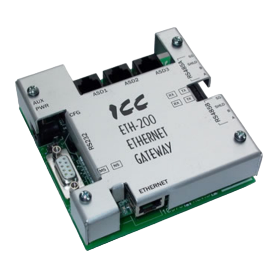
- Page 1 NETWORK GATEWAY SERIES INDUSTRIAL CONTROL COMMUNICATIONS, INC. ETH-200 ETHERNET MULTIPROTOCOL NETWORK GATEWAY August 2008 ICC #10595-1.130-001...
- Page 2 In addition, please make sure that this instruction manual is delivered to the end user of the ETH-200, and keep this instruction manual in a safe place for future reference or unit inspection.
- Page 3 ETH-200 Ethernet Multiprotocol Network Gateway User's Manual Part Number 10595-1.120-000 Printed in U.S.A. ©2007 Industrial Control Communications, Inc. All rights reserved Industrial Control Communications, Inc. reserves the right to make changes and improvements to its products without providing notice. Notice to Users INDUSTRIAL CONTROL COMMUNICATIONS, INC.’S PRODUCTS ARE NOT...
- Page 4 Usage Precautions Operating Environment • Please use the gateway only when the ambient temperature of the environment into which the unit is installed is within the following specified temperature limits: -10 ∼ +50°C (+14 ∼ +122°F) Operation: -40 ∼ +85°C (-40 ∼ +185°F) Storage: •...
-
Page 5: Table Of Contents
TABLE OF CONTENTS The Network Gateway Series Concept........7 Feature Summary................8 Installing the Gateway..............11 Mounting .....................11 3.1.1 Panel Mounting ................11 3.1.2 SnapTrack Mounting ..............12 3.1.3 DIN Rail Mounting................12 Installation for Non-Toshiba ASD Networks ........13 Toshiba Common Serial ASD Network Installation ......13 3.3.1 Installation for G7 ASDs..............14 3.3.2... - Page 6 13.1 ARP Method ..................28 13.2 Console Method ................. 29 Console Access ..............30 14.1 RS232....................30 14.1.1 Requirements................30 14.1.2 Connection................. 30 14.1.3 Application Configuration ............31 14.2 Telnet ....................33 14.2.1 Requirements................33 14.2.2 Connection................. 33 14.2.3 Application Configuration ............33 14.3 Command Overview ................
- Page 7 16.6 Teco-Westinghouse ASDs ..............63 16.6.1 MA7200 ..................63 16.6.2 PA7300..................64 16.7 Toshiba 3-Series ASD Protocol............66 16.7.1 Command Parameters ...............67 16.7.2 Monitor Parameters ..............68 16.7.3 Fundamental Parameters #1 ............72 16.7.4 Fundamental Parameters #2 ............73 16.7.5 Panel Control Parameters ............73 16.7.6 Terminal Selection Parameters ..........74 16.7.7 Special Control Parameters............78 16.7.8...
-
Page 8: The Network Gateway Series Concept
1. The Network Gateway Series Concept The ETH-200 is a member of the ICC Network Gateway Series product family. Members of this family are designed to provide a uniform interface, configuration and application experience. This commonality reduces the user’s learning curve, reducing commissioning time while simplifying support. The... -
Page 9: Feature Summary
2. Feature Summary Ethernet Port IEEE 802.3 10/100BaseT Ethernet compliant. Shielded RJ45 connector accepts standard CAT5-type 8-conductor unshielded twisted-pair (UTP) patch cables. Supports multiple simultaneous protocols. RS485 Ports Two half-duplex 2-wire RS485 ports (A / B / Signal Ground / Shield). These ports allow a selection of various master and slave protocols. - Page 10 Text-Based Console Configuration Basic unit configuration is performed via a text-based console interface, available locally over the RS232 port via a standard PC terminal program such as Microsoft Windows HyperTerminal®, or over Ethernet via a Telnet session. The unit also provides initial configuration access via ICMP (“ping”) configuration.
- Page 11 Versatile Mounting Options The unit can be panel-mounted with the included standoff kit, or snapped into existing 4” Augat SnapTrack (6TK series or equivalent). An optional mounting kit (ICC part number 10581) is also available for DIN-rail mount applications.
-
Page 12: Installing The Gateway
3. Installing the Gateway The gateway’s installation procedure will vary slightly depending on the chosen mounting method and the networks that will be used. 3.1 Mounting 3.1.1 Panel Mounting The included standoff kit allows for panel mounting of the unit. The standoff kit is comprised of four 1”... -
Page 13: Snaptrack Tm Mounting
4 corners of the unit’s cover. DO NOT press directly on the aluminum cover, as this may damage the cover. 3.1.3 DIN Rail Mounting An optional mounting kit (ICC part number 10581) allows DIN rail mounting of the unit. The mounting kit is comprised of a 4” section of Augat 6TK SnapTrack and two DIN rail clips. -
Page 14: Installation For Non-Toshiba Asd Networks
3.2 Installation for Non-Toshiba ASD Networks Note that in order to power the unit when not connecting to Toshiba ASDs via the common serial ports, the optional 120VAC/9VDC power supply (ICC part number 10456) or a user-supplied power source meeting the requirements outlined in section 10 must also be installed. -
Page 15: Installation For G7 Asds
rate is set to its maximum speed. Because the gateway will communicate to each drive only at the drive’s configured data rate, this will provide the fastest response time for drive-to-network data transfers. For information on checking the drive’s common serial communication data rate, refer to the appropriate manual supplied with your drive. - Page 16 If the drives do not appear to power up, or do not function properly, immediately turn power OFF. Repeat steps 2 and 3 to remove all power from the drives. Then, verify all connections. Contact ICC or your local Toshiba representative for assistance if the problem persists.
-
Page 17: Installation For S7, S9, S11, A7 And Vf-Nc1 Asds
The maximum allowable length for these cables is 5 meters. Although there are many varieties and styles of CAT5 UTP cables available, ICC strongly recommends using only high-quality cables from reputable manufacturers to guarantee optimal noise immunity and cable longevity. - Page 18 If the drives do not appear to power up, or do not function properly, immediately turn power OFF. Repeat steps 2 and 3 to remove all power from the drives. Then, verify all connections. Contact ICC or your local Toshiba representative for assistance if the problem persists.
-
Page 19: Rs485 Port Electrical Interfaces
4. RS485 Port Electrical Interfaces In order to ensure appropriate network conditions (signal voltage levels, etc.) when using the gateway’s RS485 ports, some knowledge of the network interface circuitry is required. Refer to Figure 4 for a simplified network schematic of the RS485 interface circuitry. Note that the “Shield” terminal has no internal connection: its purpose is simply to provide a cable shield chaining location between devices. -
Page 20: Environmental Specifications
5. Environmental Specifications Item Specification Indoors, less than 1000m above sea level, do not Operating Environment expose to direct sunlight or corrosive / explosive gasses -10 ∼ +50°C (+14 ∼ +122°F) Operating Temperature -40 ∼ +85°C (-40 ∼ +185°F) Storage Temperature 20% ∼... -
Page 21: Maintenance And Inspection
6. Maintenance and Inspection Preventive maintenance and inspection is required to maintain the gateway in its optimal condition, and to ensure a long operational lifetime. Depending on usage and operating conditions, perform a periodic inspection once every three to six months. Before starting inspections, disconnect all power sources. Inspection Points •... -
Page 22: Storage And Warranty
7.2 Warranty The gateway is covered under warranty by ICC, Inc. for a period of 12 months from the date of installation, but not to exceed 18 months from the date of shipment from the factory. -
Page 23: Led Indicators
8. LED Indicators The gateway contains several different LED indicators, each of which conveys important information about the status of the unit and connected networks. These LEDs and their functions are summarized here. 8.1 Toshiba ASD Common Serial Port Indicators Each Toshiba ASD common serial port RJ45 connector has two LEDs positioned immediately above them (1 green and 1 red). -
Page 24: Configuration Switches
10. Auxiliary Power Supply The ICC part #10456 120VAC/9VDC power supply can be used to power the unit via the AUX PWR input. If providing your own auxiliary power supply, ensure that it adheres to the following specifications: Connection diagram.... -
Page 25: Unit Configuration Concepts
12. Unit Configuration Concepts 12.1 Port and Protocol Configuration Each of the communication ports (or, in the case of the Ethernet port, the protocols) can be individually configured or enabled/disabled. It is important to note that the ports (and Ethernet protocols) function independent of one another, and can operate simultaneously. -
Page 26: Point Configuration
The timeout time adjustment range depends on the port. For the RS485 and RS232 ports, the time is adjustable in 1s increments from 0 to 500s. For the Modbus TCP/IP protocol, the time is adjustable in 1ms increments from 500ms- 30000ms (0.5s-30.0s). - Page 27 assignment will autonomously update the point’s value independent of any other protocol traffic. The “source port” designation also determines where a new point value will be written to when a “slave” protocol writes a new value to the point. For example, if an Ethernet/IP connection consumes new data that changes the value of a point, how do we know where this new value will exit the gateway to arrive at its final destination? The answer is that any new point values written by “slave”...
-
Page 28: General Configuration Procedure
into the produced assembly data of an Ethernet/IP connection, causing the gateway to act as a Modbus TCP/IP –to- Ethernet/IP router, while simultaneously performing its other network functions. Although the various configuration possibilities may seem overwhelming at first, it is clear that the gateway can perform powerful and flexible routing algorithms. Through configuration experience, the “in”... -
Page 29: Initial Ethernet Configuration
13. Initial Ethernet Configuration The gateway typically requires configuration prior to communicating on an Ethernet network. This fundamental configuration is achieved via one of two possible methods: using ICMP (“ping”) configuration via the Address Resolution Protocol (ARP), or via a text-based console interface, accessible over the RS232 serial channel and a telnet interface. -
Page 30: Console Method
essentially allows only the computer that issued the ping command to communicate with the unit. From this computer, then, the user must also access the unit’s web page via a web browser, or its console via a telnet session, in order to write the IP address to the filesystem. Until the new IP address is written to the filesystem, the IP address change is only temporary. -
Page 31: Console Access
14. Console Access 14.1 RS232 The console is accessible via an RS232 interface for direct connection to a computer’s serial (COM) port. This is performed by connecting the unit’s RS232 port to the computer’s serial port via a standard straight-thru serial cable. -
Page 32: Application Configuration
14.1.3 Application Configuration As previously mentioned, any PC communication software and PC serial port can be used. The software configuration example given here will be for Windows HyperTerminal communicating via COM1. Figure 7 shows the “Connect To” tab of the properties window for COM1. Figure 8 shows the window that appears when “Configure”... - Page 33 Figure 8: HyperTerminal Properties…Connect To…Configure Figure 9: HyperTerminal Properties…Settings...
-
Page 34: Telnet
14.2 Telnet The console is also accessible via a Telnet interface for remote administration over Ethernet once the unit is communicating on the network. The Telnet console uses well-known port 23. Note that although only 1 telnet console session can be active at any given time, the telnet console and RS232 console operate independently and can be used simultaneously. -
Page 35: Command Overview
14.3 Command Overview The console provides standard access and configuration methods for the various network parameters and configurations supported by the gateway. This section will present an overview of the supported console commands. It is important to note that unless otherwise indicated, each of these commands will become effective immediately after it has been successfully entered. - Page 36 Configuration files contain all point and port settings (but not network configuration information, such as IP address). A downloaded configuration file can be uploaded to any compatible ETH-200, allowing the user to clone multiple units with the same configuration.
- Page 37 “/u” to upload a configuration file to the unit. Figure 14 shows an example of initiating an Xmodem download in CRC mode. Once the message “The ETH-200 is ready to send its configuration file via Xmodem…Download the file now” appears, the user has 30 seconds to start the Xmodem download.
- Page 38 Figure 15: HyperTerminal receive file dialog box When uploading a file, the procedure is similar to downloading. Enter “/u” instead of “/d” for the action parameter of the xmodem command. Once the xmodem upload command is entered, the user will have 30 seconds to click the “send”...
-
Page 39: Embedded Web Server
Navigator. In this way, the unit and connected devices can be monitored, configured and controlled from across the room or from across the globe. The ETH-200’s web pages are best viewed with either Internet Explorer version 5.x and later, or Netscape Navigator version 6.x and later. The free Macromedia Flash player plug-in is also required, and can be obtained at http://www.macromedia.com/go/getflash. -
Page 40: Authentication
Figure 17: Embedded Web Server Interface 15.1 Authentication For security, the ETH-200 requires valid user authentication when the web page is accessed or the point information is modified. The authentication request will appear as a browser popup box that will request entry of a user name and password. -
Page 41: Communication Status Indicators
Figure 18: Administrator Authentication Table 1: Initial factory-set authentication values Realm Username Password Realm Applies To Blank (i.e. do not USER user Monitoring capabilities enter a password) Blank (i.e. do not ADMIN admin All change actions enter a password) 15.2 Communication Status Indicators Figure 19 shows the communication status indicators. -
Page 42: Set Date And Time
15.4 Set Date and Time Figure 21 shows the submission boxes in which new date and time information can be entered. Note that the hours are entered in military time format (0-23 = 12AM – 11PM). Figure 21: Set Date and Time 15.5 Network Configuration Figure 22 shows the submission boxes in which network configuration information can be entered. -
Page 43: Port Configuration
To change, enter your desired username and password (max 11 characters each), then click “Submit”. Contact ICC if you have forgotten your username or password for instructions on how to reset them. 15.7 Port Configuration The ETH-200 has eight ports (the Ethernet port actually acts like two independent “ports”, as the control protocols it supports can be used... -
Page 44: Toshiba Asd Common Serial Port Configuration
“nuisance” timeouts from occurring. Specifically, do not perform inadvisable behavior such as sending a request from the master device to an ETH-200, and then closing the socket prior to successfully receiving the unit’s response. The reason for this is because the gateway will then experience an error when attempting to respond via the now-closed socket, which will immediately trigger the timeout action. -
Page 45: Ethernet/Ip Port Configuration
#1, the next two bytes will be the value of point #2 and so on. 15.8 Point Configuration The ETH-200 supports 100 total points. The configuration of these points determines what data is available from attached network devices. Points are configured using the interface shown in Figure 25. - Page 46 Figure 25: Point Configuration Interface The list on the left displays the point number, name and current value for each available point. Clicking on one of these locations will load the point’s current configuration into the point box on the right, where the configuration may be edited.
- Page 47 • Source Port: This drop-down list determines the ETH-200 port that this point will obtain its value from and write values to. • Edit Protocol: This drop-down list allows the selection of any of the point’s protocol-specific attributes. Once selected, the point’s attributes related to the chosen protocol will be displayed in the middle portion of the point box.
-
Page 48: Upload Port And Point Configuration
Read only: Defines this point as read only when checked. 15.9 Upload Port and Point Configuration Once all desired changes have been made to the port and point configurations, this data must be uploaded to the ETH-200. This is performed by clicking the “SUBMIT” button shown in Figure 26. -
Page 49: Radix Selection
This process will also result in the loss of communications with all devices connected to the ETH-200. It is important to ensure that all connected devices are in a safe state such that loss of communications will not pose a danger to equipment or personnel before using this feature. -
Page 50: Error Code Reference
15.12 Error Code Reference Figure 29 shows the error code reference table, located in the bottom portion of the point box. These error codes may appear in certain situations in the point “Value” fields. Figure 29: Error Code Reference... -
Page 51: Protocol-Specific Information
16. Protocol-Specific Information This section will discuss topics that are specific to each of the available network selections. 16.1 Modbus The gateway supports Modbus slave functionality via both Modbus RTU and Modbus TCP/IP, and Modbus master functionality via Modbus RTU. The slave implementations share common access methods, which is to say they support the same functions and reference the internal points via a common “Modbus Slave”... -
Page 52: Coil & Discrete Input Mappings
the read/write registers were arranged in an alternating or scattered fashion. • Because the transaction is handled locally within the gateway, write data checking is not available. For example, if a write is performed to a register with a data value that is out-of-range of the corresponding “source port” object, no Modbus exception will be immediately returned. -
Page 53: Modbus Rtu Slave
For clarity, let’s use Equation 1 and Equation 2 in a calculation example. Say, for instance, that we are going to read coil #34. Using Equation 1, we can determine that coil #34 resides in register #3, as ⎣3.0625⎦ = ⎣3 r1⎦ = 3. Then, using Equation 2, we can determine that the bit within register #3 that coil #34 targets is (34-1)%16 = 1, as 33%16 = mod(2 r1) = 1. -
Page 54: Modbus Tcp/Ip Slave
Toshiba’s native hexadecimal radix to the Modbus protocol’s natural decimal radix) these parameter values must have 1 added to them when they are to be accessed via an ICC gateway executing the Modbus RTU master protocol. -
Page 55: Ethernet/Ip
The gateway supports the Ethernet/IP protocol (release 1.0), administered by the Open DeviceNet Vendor Association (ODVA). • This product has been self-tested by ICC, Inc. and found to comply with ODVA Ethernet/IP Conformance Test Software Version A3.7.3. • Supports unconnected messages (UCMM), and up to 16 simultaneous class 1 or class 3 connections. - Page 56 • Once instantiated, class 1 connections act independently of the encapsulation protocol sessions over which they were established. The client may therefore terminate the encapsulated session at any time with no ill affects on the class 1 transport mechanism.
-
Page 57: Toshiba Common Serial Asd Protocol
16.3 Toshiba Common Serial ASD Protocol • The gateway can act as a Toshiba ASD master via the dedicated common serial port connections. All Toshiba ASDs that include a common serial port are supported. • No configuration is necessary, as the gateway automatically adapts to the ASD’s configured characteristics. - Page 58 Figure 30: RS485 Terminal Block (CN3) and Duplex Selection Jumpers • The Toshiba RS485 terminal block connections for G7/Q7/H7/W7 drives are shown in Figure 31 for reference only. Because there are many possible RS485 port configurations & options available for the various Toshiba drives, please refer to the relevant Toshiba documentation for your drive.
- Page 59 • The drive response timeout (in seconds) is assigned via the designated port’s “Timeout” selection. If “0” is chosen (an invalid timeout time), the gateway will use a 1s timeout by default. • Network characteristics selections Baud rate: 2400 / 4800 / 9600 / 19200 / 38400 bps Parity: odd / even / none (1 stop bit) / none (2 stop bits) •...
-
Page 60: Mitsubishi Asd Protocol
16.5 Mitsubishi ASD Protocol • The gateway acts as a Mitsubishi protocol master via its RS-485 ports. Adjustable speed drives such as the FR-A500/E500/F500 series and F700- series that support the Mitsubishi protocol can be accessed. Also supported are MGI Technologies, Inc. M3000, M4000 and M5000-series drives that support the Mitsubishi protocol. - Page 61 Connect as shown in Figure 34. Figure 33: EIA/TIA Wiring Standards RDA SDA SDB RDB Signal (TB:2) Ground (TB:1) (TB:3) Figure 34: PU Port Connections • For 700-series drives, the gateway can connect to the ASD via either the PU (panel) connector as indicated in Figure 34, or via the on-board RS-485 terminals.
- Page 62 Signal (TB:1) (TB:2) Ground (TB:3) Figure 35: 700-Series ASD Connections • Note that although the 700-series ASD also supports the Modbus RTU protocol, the initial ASD firmware did not support the Modbus RTU protocol in 2-wire format. Therefore, using the Mitsubishi protocol may be the only available method to communicate with the gateway (ASD parameter 549 must be “0”).
- Page 63 on these parameters, please refer to the relevant Mitsubishi documentation. Table 4: Additional Mitsubishi Parameter Assignments Parameter Item Number 1000 Second parameter switch-over 1001 Frequency command (RAM) 1002 Frequency command (EEPROM) 1003 Frequency monitor 1004 Output current monitor 1005 Output voltage monitor 1006 Special monitor 1007...
-
Page 64: Teco-Westinghouse Asds
16.6 Teco-Westinghouse ASDs The gateway can act as a Modbus RTU protocol master via its RS232 and RS- 485 ports, which allows connection to Modbus-capable Teco-Westinghouse ASDs. While it is possible to connect to any Teco-Westinghouse ASD that supports Modbus (either RS232 or RS485), this section will discuss in particular some important considerations to make note of when connecting to, and interacting with, the PA7300 (with installed PA-M card) and MA7200 ASDs via RS485. -
Page 65: Pa7300
• The MA7200 Modbus manual indicates that control data registers (0000H..000FH) are read/write, but reading always returns 0. • All drive parameters may be read at any time, but only Cn parameters can be written while the inverter is in DRV mode. The inverter must be in PRG mode to write any other parameters. - Page 66 “known as” register value of 37, which can then be entered in the Modbus master “register” assignment of a point on the gateway.
-
Page 67: Toshiba 3-Series Asd Protocol
• The gateway can act as an RS232 master for Toshiba 3-series ASDs (G3, H3, E3 etc.) Use of the ICC “Toshiba 3-Series ASD Interface Cable” (ICC part #10603) or an equivalent cable is required to connect the gateway’s RS232 port to the drive’s on-board RS232 port. -
Page 68: Command Parameters
16.7.1 Command Parameters Parameter Function Bank Mask Adjustment Range Multiplier 0.00 ∼ 400.00Hz 0001 word Frequency command FFFF 0.01 Actual frequency will be limited by LL, UL and Fmax. ⎯ ⎯ 0002 RUN command 0: Stop 1: Run ⎯ Reserved Forward •... -
Page 69: Monitor Parameters
16.7.2 Monitor Parameters Parameter Function Bank Mask Adjustment Range Multiplier 0005 word Output frequency monitor FFFF 0.00 ~ 400.00Hz 0.01 Run • stop status ⎯ ⎯ 0006 0: Stopped 1: Running ⎯ Reserved Forward • reverse status 0: Reverse 1: Forward Accel / decel #1 / #2 selection 0: Accel / decel #1 status... - Page 70 Parameter Function Bank Mask Adjustment Range Multiplier ⎯ 0012 high 2nd past trip 7F00 byte 1st past trip (oldest) 007F byte 0000 ∼ 9C40 0013 word Pre-compensation output FFFF 0.01 (0.00 ∼ 400.00 Hz) frequency 0000 ∼ 9C40 0014 word Post-compensation output FFFF 0.01...
- Page 71 Table 5: Input Terminal Status Monitor (parameter 000D) Single-Bit Input Terminal Read Mask bit 0 terminal - CC open terminal - CC shorted 0001 bit 1 terminal - CC open terminal - CC shorted 0002 bit 2 terminal - CC open terminal - CC shorted 0004 Lower...
- Page 72 Table 7: Inverter Status 1 (parameter 000F) Single-Bit Inverter Status Read Mask ⎯ bit 0 running (accel/decel) running 0001 ⎯ ⎯ ⎯ bit 1 unused (always 0) bit 2 forward / reverse reverse forward 0004 Lower bit 3 accel/decel #1/#2 accel/decel #1 accel/decel #2 0008...
-
Page 73: Fundamental Parameters #1
16.7.3 Fundamental Parameters #1 Parameter Function / Title Bank Mask Adjustment Range Multiplier 0BB8 ∼ 9C40 (30.00∼400.00) MAXIMUM OUTPUT 0026 0 / 1 FFFF 0.01 FREQUENCY 09C4 ∼ 9C40 (25.00∼400.00) BASE FREQUENCY #1 0027 0 / 1 FFFF 0.01 ⎯ 0028 BASE FREQUENCY 0 / 1... -
Page 74: Fundamental Parameters #2
16.7.4 Fundamental Parameters #2 Parameter Function / Title Bank Mask Adjustment Range Multiplier 09C4 ∼ 9C40 (25.00 ∼ 400.00) BASE FREQUENCY #2 0034 0 / 1 FFFF 0.01 0000 ∼ 0258 (0 ∼ 600) MAXIMUM OUTPUT 0035 0 / 1 FFFF VOLTAGE #2 0000 ∼... -
Page 75: Terminal Selection Parameters
16.7.6 Terminal Selection Parameters Parameter Function / Title Bank Mask Adjustment Range Multiplier ⎯ INPUT TERMINAL 0044 0 / 1 0001 0000: Standard functions SELECTION 0001: Individual selections 0000 ∼ FFFF (0 ∼ 54) ⎯ “R” INPUT TERMINAL 0045 0 / 1 FFFF FUNCTION 0046... - Page 76 Parameter Function / Title Bank Mask Adjustment Range Multiplier 0 ∼ Fmax LOW SPEED SIGNAL 0061 0 / 1 FFFF 0.01 OUTPUT FREQ 0 ∼ Fmax ACC/DEC COMPLETE 0062 0 / 1 FFFF 0.01 DETECT BAND 0 ∼ Fmax SPEED REACH MAXIMUM 0063 0 / 1 FFFF...
- Page 77 Table 9: Input Terminal Selections Setting Data Setting Data Function Function Value (Hex) Value (Hex) 10C8 (reverse run) 04AF Binary bit #6 011C (preset speed selection) 08AF Binary bit #7 021C (preset speed selection) 10AF Binary bit #8 041C (preset speed selection) 20AF Binary bit #9 081C...
- Page 78 Table 10: Output Terminal Selections (RCH, LOW, FL, OUT relay contacts) Setting Data Setting Data Function Function Value (Hex) Value (Hex) 0000 Lower limit frequency C5B7 Executing emergency off 0100 /Lower limit frequency CDB7 /Executing emergency off 0200 Upper limit frequency B5BB Executing retry 0300...
-
Page 79: Special Control Parameters
16.7.7 Special Control Parameters Parameter Function / Title Bank Mask Adjustment Range Multiplier 0000 ∼ 03E8 (0.00 ∼ 10.00) START-UP FREQUENCY 0069 0 / 1 FFFF 0.01 006A ∼ ⎯ ⎯ ⎯ ⎯ Reserved 006F 0000 ∼ 0BB8 (0.00 ∼ 30.00) 0070 END FREQUENCY 0 / 1... -
Page 80: Frequency Setting Parameters
16.7.8 Frequency Setting Parameters Parameter Function / Title Bank Mask Adjustment Range Multiplier ⎯ FREQUENCY PRIORITY 0081 0 / 1 0007 0001: RR SELECTION #1 0002: IV 0003: RX 0004: PG 0005: BIN ⎯ FREQUENCY PRIORITY 0082 0 / 1 0038 0008: RR SELECTION #2... - Page 81 Parameter Function / Title Bank Mask Adjustment Range Multiplier ⎯ BINARY INPUT STD OR 0098 0 / 1 0001 0000: Standard ADJUSTABLE 0001: Adjustable 0000 ∼ 0064 (0 ∼ 100) 0099 BINARY REF SETTING 0 / 1 00FF POINT #1 -Fmax ∼...
- Page 82 Parameter Function / Title Bank Mask Adjustment Range Multiplier higher PRESET SPEED 0110 040C Same as PRESET SPEED #1 #8 OPERATING OPERATING MODE MODE LL ∼ UL 0111 PRESET SPEED FFFF 0.01 #9 FREQUENCY 9 or PRESET SPEED 0112 040C Same as PRESET SPEED #1 higher #9 OPERATING...
-
Page 83: Protection Function Parameters
16.7.9 Protection Function Parameters Parameter Function / Title Bank Mask Adjustment Range Multiplier ⎯ DYNAMIC BRAKING 011F 0 / 1 0003 0000: no dynamic braking SELECTION 0001: with dynamic braking, no DBR overload trip 0003: with dynamic braking and DBR overload trip 000A ∼... - Page 84 Parameter Function / Title Bank Mask Adjustment Range Multiplier ⎯ STALL PROTECTION 0133 0 / 1 0040 0000: ON ENABLE 0040: OFF 000A ∼ 00D7 (10 ∼ 215) 0134 STALL 0 / 1 00FF PROTECTION CURRENT LEVEL ⎯ UNDERVOLTAGE TRIP 0135 0 / 1 0080...
-
Page 85: Pattern Run Control Parameters
16.7.10 Pattern Run Control Parameters Parameter Function / Title Bank Mask Adjustment Range Multiplier ⎯ PATTERN RUN SELECTION 0146 0 / 1 0008 0000: OFF 0008: ON ⎯ PATTERN RUN 0147 0 / 1 0001 0000: reset on stop CONTINUE MODE 0001: switch when done 0148 PATTERN GROUP #1... - Page 86 Parameter Function / Title Bank Mask Adjustment Range Multiplier 0001 ∼ 000F: Speeds 1 ∼ 15 PATTERN GROUP #4 016A SPEED #1 PATTERN GROUP #4 016B SPEED #2 PATTERN GROUP #4 016C SPEED #3 PATTERN GROUP #4 016D SPEED #4 PATTERN GROUP #4 016E SPEED #5...
- Page 87 Parameter Function / Title Bank Mask Adjustment Range Multiplier 0000 ∼ 1F40 (0 ∼ 8000) SPEED #10 0185 FFFF < 4 DRIVE TIME ⎯ SPEED #11 0186 00FF Same as SPEED #1 CONTINUE CONTINUE MODE MODE 0000 ∼ 1F40 (0 ∼ 8000) SPEED #11 0187 FFFF...
-
Page 88: Feedback Control Parameters
16.7.11 Feedback Control Parameters Parameter Function / Title Bank Mask Adjustment Range Multiplier ⎯ FEEDBACK CONTROL 0190 0 / 1 0060 0020: No feedback SELECTION 0040: PID control 0060: Speed feedback ⎯ 0191 FEEDBACK INPUT 0 / 1 001C 0004: RR input SIGNAL 0008: IV input SELECTION... -
Page 89: Communication Setting Parameters
16.7.12 Communication Setting Parameters Parameter Function / Title Bank Mask Adjustment Range Multiplier 0000 ∼ 00FF (0 ∼ 255) INVERTER ID NUMBER 0204 00FF ⎯ COMMUNICATION 0205 0007 0000: OFF SELECTION 0001: RS485 0002: Modbus, F10, DeviceNet (2) 0003: TOSLINE S-20 0004: 12 bit binary input 0005: 3-digit BCD (0.1Hz) 0006: 3-digit BCD (1Hz) -
Page 90: Am/Fm Terminal Adjustment Parameters
16.7.13 AM/FM Terminal Adjustment Parameters Parameter Function / Title Bank Mask Adjustment Range Multiplier ⎯ FM TERMINAL FUNCTION 0218 0 / 1 FFFF 1194: Pre-comp ref. frequency SELECTION 6686: Post-comp output freq. 1500: Frequency setting 2576: Output current 2689: DC voltage 5668: Output voltage 3684: Torque current 2688: Excitation current... -
Page 91: Utility Parameters
16.7.14 Utility Parameters Parameter Function / Title Bank Mask Adjustment Range Multiplier ⎯ INDUSTRIAL 021C 0 / 1 00FF 0000: Standard shipment setting APPLICATIONS 0001: Pump application (previous setting monitor 0002: Fan application for read use only) 0003: Conveyor application 0004: Hoist application 0005: Textiles application 0006: Machine tools application... - Page 92 Parameter Function / Title Bank Mask Adjustment Range Multiplier ⎯ 022D 0 / 1 0004 0000: 0.1 sec. ACC/DEC TIME UNITS SELECTION 0004: 0.01 sec. ⎯ 022E 0 / 1 0008 0000: % CURRENT UNITS SELECTION 0008: A ⎯ 022F 0 / 1 0010 0000: %...
-
Page 93: Motor Rating Parameters
16.7.15 Motor Rating Parameters Parameter Function / Title Bank Mask Adjustment Range Multiplier NUMBER OF MOTOR POLES 0242 0 / 1 00FF 0001: 0002: 0003: 0004: 0005: (10) 0006: (12) 0007: (14) 0008: (16) 0001 ∼ 270F (0.1 ∼ 999.9) 0243 MOTOR RATED CAPACITY 0 / 1... -
Page 94: Inverter Fault Codes
16.7.16 Inverter Fault Codes Data LCD Display Message Explanation (Hex) ××00 NO ERROR No error has been recorded since the last inverter reset or trip clear ××01 OVERCURRENT (ACCEL) Overcurrent during acceleration (PRESS CLEAR) ××02 OVERCURRENT (DECEL) Overcurrent during deceleration (PRESS CLEAR) ××03 OVERCURRENT (RUN) - Page 95 Data LCD Display Message Explanation (Hex) ××1B OPTION PCB ERROR Option PCB error (PRESS CLEAR) ××1C OPTION ROM ERROR Option ROM error ××1D LOW CURRENT TRIP Low current (PRESS CLEAR) ××1E UNDERVOLTAGE TRIP Main circuit undervoltage (PRESS CLEAR) ⎯ ××1F Unused ××20 OVERTORQUE TRIP...
-
Page 96: Firmware Updates
ICC is continually striving to enhance the functionality and flexibility of our products, and we therefore periodically release new embedded firmware to achieve these goals and meet customer requests. Flash firmware files and all... -
Page 97: Using The Rfu Utility
Support for downloading new application firmware to the gateway is provided by the free Rabbit Field Utility (RFU), which is a 32-bit application that runs on Microsoft Windows platforms. The RFU utility can be downloaded from ICC’s home page at http://www.iccdesigns.com. When downloading a new gateway application BSP, always confirm that you also have the latest version of RFU, as new .BIN firmware files contained in BSPs may require functionality found... -
Page 98: Transmitting Firmware Files
“Comm Port” settings, which depends on the COM port you are using. Click “OK” when complete. Figure 37: Communications Options Window Next, select the “Setup…File Locations” menu item from the main screen. The “Choose File Locations” window shown in Figure 38 then appears. Confirm that the correct paths to the referenced files are entered. - Page 99 Once the RFU utility has been configured, the flash firmware files can be downloaded to the gateway by two different methods. The simplest way is to drag the application firmware .BIN file’s icon and drop it onto the RFU utility’s main screen.
-
Page 100: Wrap-Up
17.4 Wrap-Up Once downloading is complete, close the RFU utility, move “CFG” switch #1 back to the “OFF” (left-hand) position to exit “firmware download” mode, and cycle power momentarily to the unit by either disconnecting the auxiliary power supply and/or powering down all connected drives or momentarily removing all drive communication cables from the unit. -
Page 101: Notes
18. Notes... - Page 103 INDUSTRIAL CONTROL COMMUNICATIONS, INC. Madison Office Houston Office 1600 Aspen Commons, Suite 210 12300 Dundee Court, Suite 212 Middleton, WI USA 53562-4720 Cypress, TX USA 77429-8364 Tel: [608] 831-1255 Fax: [608] 831-2045 http://www.iccdesigns.com Printed in U.S.A...
Need help?
Do you have a question about the ETH-200 and is the answer not in the manual?
Questions and answers