ICC XLTR-1000 Instruction Manual
Multiprotocol rs-485
Hide thumbs
Also See for XLTR-1000:
- Instruction manual (104 pages) ,
- Quick start manual (8 pages) ,
- Instruction manual (157 pages)

Related Manuals for ICC XLTR-1000


Summary of Contents for ICC XLTR-1000
- Page 1 Instruction Manual INDUSTRIAL CONTROL COMMUNICATIONS, INC. XLTR-1000 Multiprotocol RS-485 Gateway January 1, 2016 © 2016 Industrial Control Communications, Inc. ICC #10756...
- Page 2 XLTR-1000 User's Manual Part Number 10756 Printed in U.S.A. ©2016 Industrial Control Communications, Inc. All rights reserved OTICE SERS Industrial Control Communications, Inc. reserves the right to make changes and improvements to its products without providing notice. Industrial Control Communications, Inc. shall not be liable for technical or...
- Page 3 Usage Precautions Operating Environment • Please use the interface only when the ambient temperature of the environment into which the unit is installed is within the following specified temperature limits: Operation: -10 ∼ +60°C (+14 ∼ +140°F) Storage: -40 ∼ +85°C (-40 ∼ +185°F) Avoid installation locations that may be subjected to large shocks or •...
-
Page 4: Table Of Contents
Grounding ..................... 18 LED Indicators ................19 Gateway Status ..................19 RS-485 Network Status ................ 19 Configuration Concepts ............20 ICC Configuration Studio ..............20 General Object Editing Activities ............23 8.2.1 Device Settings ................24 8.2.2 USB Virtual COM Port Settings ............. 25 8.2.3... - Page 5 10. Troubleshooting ................. 37 11. Appendix A: Database Endianness .......... 38 11.1 Modbus - PROFIBUS Example ............. 40 11.2 Modbus - DeviceNet Example ............... 41 11.3 BACnet - DeviceNet Example ............... 42 11.4 BACnet - Modbus Analog Element Example......... 44 11.5 BACnet - Modbus Binary Element Example..........
-
Page 6: Introduction
Note that different gateway firmware versions may provide varying levels of support for the various protocols. For optimal performance, always ensure that you are using the latest version of the ICC Configuration Studio and included firmware. This manual will primarily be concerned with the gateway’s hardware specifications, installation, wiring, configuration and operational characteristics. -
Page 7: Features
The gateway can be connected to a PC via a USB mini type-B cable. This simultaneously supplies power while providing the ability to configure the gateway, monitor data, and update firmware on the device using the ICC Configuration Studio. Refer to section 8.1 for more information. - Page 8 Flexible Mounting Capabilities The gateway includes all hardware for desktop, panel/wall and DIN-rail mounting capabilities. Refer to section 6.1 for more information.
-
Page 9: Gateway Concepts
3. Gateway Concepts The XLTR-1000 is a member of the Millennium Series communication gateways. Members of this family are designed to provide a uniform interface, configuration and application experience. This commonality reduces the user’s learning curve, reducing commissioning time while simplifying support. All Millennium Series gateways are configured using the ICC Configuration Studio. - Page 10 The Millennium Series gateways also provide a powerful data-monitoring feature that allows the user to view and edit the database in real time, as well as view the status of service objects via the ICC Configuration Studio’s Database panel when connected via USB to a PC.
-
Page 11: Precautions And Specifications
4. Precautions and Specifications Rotating shafts and electrical equipment can be hazardous. Installation, operation, and maintenance of the gateway shall be performed by Qualified Personnel only. Qualified Personnel shall be: • Familiar with the construction and function of the gateway, the equipment being driven, and the hazards involved. -
Page 12: Maintenance Precautions
4.2 Maintenance Precautions • Do Not attempt to disassemble, modify, or repair the gateway. Contact your ICC sales representative for repair or service information. • If the gateway should emit smoke or an unusual odor or sound, turn the power off immediately. -
Page 13: Storage
4.6 Warranty This gateway is covered under warranty by ICC, Inc. for a period of 12 months from the date of installation, but not to exceed 18 months from the date of shipment from the factory. For further warranty or service information, please contact Industrial Control Communications, Inc. -
Page 14: Gateway Overview
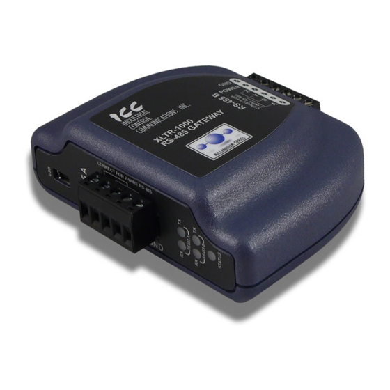
5. Gateway Overview USB connector “RS-485 A” terminal block “RS-485 A” TX and RX LEDs “RS-485 B” TX and RX LEDs Gateway status LED Gateway Overview (Front) Power terminals “RS-485 B” terminals Shield terminal Gateway Overview (Back) -
Page 15: Power Supply Electrical Interface
Voltage rating ......7 - 24VDC Minimum Current rating ..50mA (@24VDC) Typical current consumption of the XLTR-1000 when powered from a 24V • supply is approximately 15mA. ICC offers an optional 120VAC/12VDC power supply (ICC part number •... - Page 16 Figure 2: RS-485 Interface Circuitry Schematic Figure 3 highlights the terminals on the gateway’s “RS-485 B” terminal block that are specific to RS-485 network connections. Equivalent terminals exist on the “RS-485 A” terminal block for connection to that separate subnet. Figure 3: “RS-485 B”...
-
Page 17: Installation
6. Installation The gateway’s installation procedure will vary slightly depending on the mounting method used. Before mounting the gateway, install the 4 black rubber feet (Figure 4) onto the bottom of the enclosure. Figure 4: Rubber Feet 6.1 Mounting the Gateway The gateway may be mounted on a panel, a wall or a DIN rail. -
Page 18: Din Rail Mounting
6.1.2 DIN Rail Mounting The DIN rail adapter (Figure 6) can clip onto 35mm and G-type rails. To mount the gateway to a DIN rail, clip the DIN rail adapter onto the DIN rail and mount the gateway on the screws (the screws should already be seated into the adapter at the proper height). -
Page 19: Wiring Connections
6.2 Wiring Connections Note that in order to power the unit, a power supply must also be installed. Refer to section 5.1 for more information. Mount the unit via the desired method (refer to section 6.1). Connect the various networks to their respective plugs/terminal blocks. Ensure that any wires are fully seated into their respective terminal blocks, and route the network cables such that they are located well away from any electrical noise sources, such as adjustable-speed drive input power or... -
Page 20: Led Indicators
7. LED Indicators The gateway contains several different LED indicators, each of which conveys important information about the status of the unit and connected networks. These LEDs and their functions are summarized here. 7.1 Gateway Status The gateway has one dichromatic LED to indicate the status of the device. On startup, the LED blinks a startup sequence: Green, Red, Green, Red. -
Page 21: Configuration Concepts
PC. The gateway is configured by the ICC Configuration Studio PC application, and this section will provide only a brief introduction to the configuration concepts. For more detailed information on how to install and use the Configuration Studio, refer to the separately-available training resources. - Page 22 Uploading a Device’s Configuration into a Project The current configuration of an online device can be uploaded into the Project panel by selecting a device under the Online Devices list heading and then: Right-clicking on it and choosing Upload Configuration from the •...
- Page 23 Downloading a Configuration to a Device To download a configuration to an online device, first select the device under the Device Configurations heading in the Project panel, and then navigate to Device…Download Configuration to Device. If the studio is currently online with only one compatible device, then the configuration will be downloaded to the online device.
-
Page 24: General Object Editing Activities
8.2 General Object Editing Activities The following editing activities apply for all types of configuration objects and project elements. Adding an Object To add an object, click on an item (protocol driver or Node, for example) in the Project panel. Any available objects for that item will be listed in the Available Objects panel (the panel title depends on the currently-selected item). -
Page 25: Device Settings
Copying and Pasting an Object To copy an object, first click on an item in the Project panel. An object can then be copied by: Right-clicking on it and choosing Copy from the context-sensitive menu. • Pressing the <CTRL+C> keys on the keyboard. •... -
Page 26: Usb Virtual Com Port Settings
Database Endianness Selection Select the desired endianness for how data will be stored in the device’s internal database for multi-byte data types. For more information on database endianness, refer to Appendix A: Database Endianness. 8.2.2 USB Virtual COM Port Settings The device can be configured to enumerate as a USB virtual COM port, providing direct serial communications between the device and a PC through the USB connection. -
Page 27: Usb Serial Capture Window
receive error occurs on one or more characters of a packet, the sniffer will output the characters “ERR: Receive Error”. Note that because the serial sniffer mode captures packets at the protocol driver level, a protocol must be configured on the selected serial port to provide data to the USB virtual COM port. - Page 28 Clearing the Capture Log All captured data may be cleared at any time while connected to a device or after disconnecting from a device. This will also reset the connection time duration and all counters. To reset all captured data, perform one of the following actions: Select Clear Log from the Edit menu.
-
Page 29: Batch Update Mode
• 8.2.4 Batch Update Mode The ICC Configuration Studio supports a batch update mode for quickly updating firmware, and optionally, the configuration on all discovered devices without user interaction. While in batch update mode, the studio will automatically go online with a device, update the firmware, update the configuration if a matching configuration is found in the project, and then go offline with the device. -
Page 30: Internal Logic Settings
At the end of the log, the studio records statistics for the batch update session. The statistics include the following information: Devices Discovered The total number of devices discovered while in batch update mode. Successful The total number of devices that were updated successfully. Failed The total number of devices that the studio failed to update. - Page 31 8.3.1.2 Timeout Time The timeout time is the maximum number of milliseconds for a break in network communications before a timeout will be triggered. This timeout setting is configured at the protocol level as part of a driver’s configuration, and used by the protocol drivers themselves to determine abnormal loss-of-communications conditions.
-
Page 32: Database Logic
8.3.2 Database Logic 8.3.2.1 Overview A variety of database logic operations are included which provide PLC-style manipulation of database values. Categories such as logical, arithmetic and filtering operations allow for autonomous control over value modification and data movement within the database. High-level signal conditioning is also realizable via the construction of compound formulas derived from the elemental building block operations provided. - Page 33 The Indirect Copy operation outputs the value at the database location • specified by the input source to the database location specified by the output destination. This operation can be used to access different database locations dynamically. It could also be used to create reusable database logic subroutines by selecting a different input and output location for the subroutine during each execution cycle.
- Page 34 The Cosine operation calculates the expression cos(Input 1), where Input1 is • in radians. The Tangent operation calculates the expression tan(Input 1), where Input1 • is in radians. • The Arc Sine operation calculates the expression sin (Input 1), where the output is in radians.
-
Page 35: Service Objects And Diagnostics Objects
database operation can be used for this purpose, such a scenario may most typically use the output of a “compare” operation in order to control whether or not other operations should execute (e.g. execute a certain operation only when some process variable is greater than a certain value, etc.) Allowing the conditional execution of database logic operations to be based on data values obtained via communications or as a result of other database logic operations enables the construction of flexible, hierarchical and dynamic data evaluation and... - Page 36 Master/client drivers commonly also provide the ability to debug configured service objects while the driver is running by way of optional diagnostics objects. Where supported, diagnostics objects can be added to each service object, and a database address can be designated at which to store the status information. The diagnostics object is a 16-byte structure containing elements such as a transmission counter, receive counter, receive error counter, current status, and the last error of the defined service object.
-
Page 37: Rs-485 Drivers
9. RS-485 Drivers The gateway supports a variety of serial drivers on its RS-485 ports. For a list of supported protocols, refer to the Millennium Series Supported Drivers List. For detailed information on each protocol, refer to the specific protocol’s driver manual. -
Page 38: Troubleshooting
Any other number of flashes generated error the LED flashes indicates an internal device error. indicates an error Record the blink sequence and code contact ICC for further assistance. Unplug and reconnect the USB • The USB cable is cable. plugged into both the Try a different USB cable. -
Page 39: Appendix A: Database Endianness
11. Appendix A: Database Endianness A key feature of the Millennium Series gateways is the ability to change the byte order storage scheme for data in the database between big endian and little endian. The database endianness is the convention used to store multi-byte data to or retrieve multi-byte data from the database. - Page 40 Similarly, data is retrieved from the database starting at the low address. The endianness decides whether the first byte is interpreted as the least-significant byte or the most-significant byte of the multi-byte number. Here are some examples that demonstrate this. Figure 12 shows how the hex value 0x12345678 is retrieved from the database using a big endian byte order.
-
Page 41: Modbus - Profibus Example
simply stored into the database in the order they were received. Gateway endianness selection therefore has no effect on data storage or retrieval with a “bag of bytes” protocol driver. The other method is that used by networks that exchange data by means of an “object value”... -
Page 42: Modbus - Devicenet Example
In contrast, Figure 15 shows the effects of configuring the database for little- endian byte order. Holding registers 1 and 2 again have values of 0x1234 and 0x5678, respectively. However, when the PROFIBUS device receiving the input data from the gateway interprets these values, the resulting pairs of 2-byte values become 0x3412 and 0x7856, thus receiving incorrect values for holding registers 1 and 2. -
Page 43: Bacnet - Devicenet Example
Figure 16: Modbus - DeviceNet Little Endian In contrast, Figure 17 shows the effects of configuring the database for big- endian byte order. Holding registers 1 and 2 again have values of 0x1234 and 0x5678, respectively. However, when the DeviceNet device receiving the input data from the gateway interprets these values, the resulting pairs of 2-byte values become 0x3412 and 0x7856, thus receiving incorrect values for holding registers 1 and 2. - Page 44 reads analog value 0 from the BACnet network, stores the data into the database, and sends the input data onto the DeviceNet network. Figure 18 demonstrates the data flow from the BACnet network to the DeviceNet network through a gateway configured to use a little endian database. Because the DeviceNet specification defines multi-byte values within the byte array to be interpreted as little endian, it is recommended that the database be configured for little-endian byte order when using DeviceNet.
-
Page 45: Bacnet - Modbus Analog Element Example
Figure 19: BACnet - DeviceNet Big Endian 11.4 BACnet - Modbus Analog Element Example This example exhibits two networks that both use an object value scheme to exchange data. In this scenario, the database endianness is irrelevant if the data types are the same for both networks. -
Page 46: Bacnet - Modbus Binary Element Example
Figure 21: BACnet - Modbus (Analog Objects & Registers) Little Endian 11.5 BACnet - Modbus Binary Element Example This example also contains two networks that both employ an object value method for exchanging data, but unlike the previous example, the database endianness does affect the end-to-end alignment of the data. - Page 47 Figure 22: BACnet - Modbus (Binary Objects & Discretes) Little Endian However, when the database is configured for a big-endian byte order, binary values 1…8 correspond to coils 9…16, binary values 9…16 correspond to coils 1…8, and so on. This can be seen in Figure 23. Since the most significant bytes of the Modbus registers that the coils map to are now mapped to lower addresses, the alignment between the two networks’...
-
Page 48: Appendix B: Diagnostics Objects
12. Appendix B: Diagnostics Objects This section details the information that is enabled by adding a diagnostics object to a service object. Figure 24 diagrams the structure of this status information. Because this 16-byte structure resides in the database at a user-designated location, it can be accessed from any supported network or protocol in order to continuously determine the health and performance of the corresponding service object. - Page 49 Table 1: Status / Error Codes Status / Error Description Code (Hex) 0x00 No Error 0xF0 Invalid Data Address 0xF1 Data Error 0xF2 Write To Read-Only 0xF3 Read From Write-Only 0xF4 Target Busy 0xF5 Target Error 0xF6 Cannot Execute 0xF7 Mode Error 0xF8 Other Error...
-
Page 50: Appendix C: Bacnet Pics
V5.000 BACnet Protocol Revision: Product Description: The XLTR-1000 is a multiprotocol RS-485 to RS-485 gateway. This product supports native BACnet, connecting directly to the MS/TP LAN using baud rates of 9600, 19200, 38400, 57600, 76800, and 115200. The device can be configured as a BACnet Client or as a BACnet Server. - Page 51 Standard Object Types Supported: See “Object Types/Property Support Table” for object details. Data Link Layer Options: BACnet IP, (Annex J) BACnet IP, (Annex J), Foreign Device ISO 8802-3, Ethernet (Clause 7) ANSI/ATA 878.1, 2.5 Mb. ARCNET (Clause 8) ANSI/ATA 878.1, RS-485 ARCNET (Clause 8), baud rate(s) ______ MS/TP master (Clause 9), baud rate(s): 9600, 19200, 38400, 57600, 76800, 115200 MS/TP slave (Clause 9), baud rate(s): ______...
- Page 52 If this product is a communication gateway, describe the types of non-BACnet equipment/networks(s) that the gateway supports: Refer to protocol-specific manuals for other supported protocols.
- Page 53 Object Types/Property Support Table The following table summarizes the Object Types/Properties supported. Object Type Property AV MSI MSO MSV Object Identifier Object Name Object Type System Status Vendor Name Vendor Identifier Model Name Firmware Revision App Software Revision Protocol Version Protocol Revision Services Supported Object Types Supported...
- Page 54 INDUSTRIAL CONTROL COMMUNICATIONS, INC. 1600 Aspen Commons, Suite 210 Middleton, WI USA 53562-4720 Tel: [608] 831-1255 Fax: [608] 831-2045 http://www.iccdesigns.com Printed in U.S.A...
Need help?
Do you have a question about the XLTR-1000 and is the answer not in the manual?
Questions and answers