Table of Contents
Advertisement
Quick Links
Advertisement
Table of Contents

Related Manuals for ICC DNET-100


Summary of Contents for ICC DNET-100
- Page 1 NETWORK GATEWAY SERIES INDUSTRIAL CONTROL COMMUNICATIONS, INC. INDUSTRIAL CONTROL COMMUNICATIONS, INC. INDUSTRIAL CONTROL COMMUNICATIONS, INC. INDUSTRIAL CONTROL COMMUNICATIONS, INC. DNET-100 DEVICENET MULTIPROTOCOL NETWORK GATEWAY December 2003 ICC #10519-1.000-000...
- Page 2 In addition, please make sure that this instruction manual is delivered to the end user of the DNET-100, and keep this instruction manual in a safe place for future reference or unit inspection.
- Page 3 DNET-100 DeviceNet Multiprotocol Network Gateway User's Manual Part Number 10519-1.000-000 Printed in U.S.A. ©2003 Industrial Control Communications, Inc. All rights reserved Industrial Control Communications, Inc. reserves the right to make changes and improvements to its products without providing notice. Notice to Users INDUSTRIAL CONTROL COMMUNICATIONS, INC.’S PRODUCTS ARE NOT...
- Page 4 Usage Precautions Operating Environment • Please use the gateway only when the ambient temperature of the environment into which the unit is installed is within the following specified temperature limits: -10 ∼ +50°C (+14 ∼ +122°F) Operation: -40 ∼ +85°C (-40 ∼ +185°F) Storage: •...
-
Page 5: Table Of Contents
TABLE OF CONTENTS The Network Gateway Series Concept ........6 Mechanical Diagrams ..............7 Enclosure ....................7 Mounting Clip ..................8 External Interface ..................9 Feature Summary................11 Installing the Interface..............14 RS-485 Secondary Network..............14 Toshiba ASD (Common Serial) Secondary Network......15 4.2.1 Installation for G7 ASDs ..............15 4.2.2 Installation for S7, S9, A7 and VF-nC1 ASDs.........17 RS-485 Electrical Interface............19... - Page 6 Load Points................48 13.5.4 New Points................. 49 13.5.5 Xmodem Point File ..............50 13.5.6 Xmodem EDS File ..............53 13.5.7 DNET-100 Information............... 54 13.5.8 Exit & Restart................55 Network-Specific Information ..........56 14.1 DeviceNet (Primary) Network ............. 56 14.2 Secondary Networks ................58 14.2.1...
-
Page 7: The Network Gateway Series Concept
1. The Network Gateway Series Concept The DNET-100 is a member of the ICC Network Gateway Series product family. Members of this family are designed to provide a uniform interface, configuration and application experience. This commonality reduces the user’s learning curve, reducing commissioning time while simplifying support. -
Page 8: Mechanical Diagrams
2. Mechanical Diagrams 2.1 Enclosure Figure 2: Enclosure Dimensions (units are inches) -
Page 9: Mounting Clip
2.2 Mounting Clip Figure 3: Mounting Clip Dimensions (units are inches) -
Page 10: External Interface
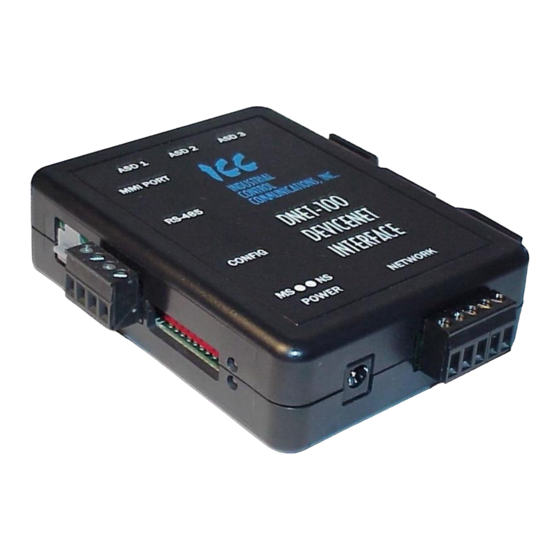
2.3 External Interface DeviceNet Power Network Figure 4: Bottom View Network RS-485 Tx RS-485 Rx Status LED Secondary Configuration Module Status Port RS-485 Switches Figure 5: Front View... - Page 11 Reserved LEDs ASD Link ASD #3 ASD #2 ASD #1 LEDs Figure 6: Top View...
-
Page 12: Feature Summary
Set. Supports the Polled and COS/Cyclic I/O connections, with consumed and produced data sizes for each connection independently selectable from 0 to 200 bytes. This product has been self-tested by ICC, Inc. and found to comply with ODVA Conformance Test Software Version A-13. - Page 13 / downloaded to a PC, which provides the capability for PC- based file backup and easy configuration copying to multiple units. Sample point files and related documentation can also be downloaded from the ICC web site, uploaded to a unit, and custom-modified to suit a specific application.
- Page 14 • For panel mounting, the mounting clip can be bolted directly to a flat panel via the two bolt holes at the top and bottom of the clip. Refer to section 2.2 for mounting clip mechanical details. Once the mounting clip is securely attached to the panel, the unit enclosure can be snapped onto the clip’s retaining tabs.
-
Page 15: Installing The Interface
4.1 RS-485 Secondary Network Note that in order to power the unit when using the secondary RS-485 network, you must also purchase the optional 120VAC/9VDC power supply (ICC part number 10456). Attach the mounting clip and unit enclosure in your desired manner (refer to page 12 for more information). -
Page 16: Toshiba Asd (Common Serial) Secondary Network
4.2 Toshiba ASD (Common Serial) Secondary Network The gateway connects to each drive via the drive’s common serial (logic level) communication port, typically located on either the main drive control board (G7), on the front of the drive enclosure under a small snap-on cover (A7, S9), on the right-hand side of the drive enclosure under a small snap-on cover (S7), or on the bottom side of the drive enclosure (VF-nC1). - Page 17 The maximum allowable length for these cables is 5 meters. Although there are many varieties and styles of CAT5 UTP cables available, ICC strongly recommends using only high-quality cables from reputable manufacturers to guarantee optimal noise immunity and cable longevity.
-
Page 18: Installation For S7, S9, A7 And Vf-Nc1 Asds
OFF. Repeat steps 1 and 2 to remove all power from the drives. Then, verify all connections. Contact ICC or your local Toshiba representative for assistance if the problem persists. 4.2.2 Installation for S7, S9, A7 and VF-nC1 ASDs... - Page 19 If the drives do not appear to power up, or do not function properly, immediately turn power OFF. Repeat steps 1 and 2 to remove all power from the drives. Then, verify all connections. Contact ICC or your local Toshiba representative for assistance if the problem persists.
-
Page 20: Rs-485 Electrical Interface
5. RS-485 Electrical Interface In order to ensure appropriate network conditions (signal voltage levels, etc.), some knowledge of the gateway’s RS-485 network interface circuitry is required. Refer to Figure 7 for a simplified network schematic of the secondary RS-485 interface circuitry. Note that the “Shield” terminal has no internal connection: its purpose is simply to provide a cable shield chaining location between devices. -
Page 21: Environmental Specifications
6. Environmental Specifications Item Specification Indoors, less than 1000m above sea level, do not Operating Environment expose to direct sunlight or corrosive / explosive gasses -10 ∼ +50 ° C (+14 ∼ +122 ° F) Operating Temperature Storage Temperature -40 ∼ +85 ° C (-40 ∼ +185 ° F) Relative Humidity 20% ∼... -
Page 22: Maintenance And Inspection
7. Maintenance and Inspection Preventive maintenance and inspection is required to maintain the gateway in its optimal condition, and to ensure a long operational lifetime. Depending on usage and operating conditions, perform a periodic inspection once every three to six months. Before starting inspections, disconnect all power sources (with ASD connections, turn off all power supplies to connected drives and wait at least five minutes after each drive’s “CHARGE”... -
Page 23: Storage And Warranty
8.2 Warranty The gateway is covered under warranty by ICC, Inc. for a period of 12 months from the date of installation, but not to exceed 18 months from the date of shipment from the factory. -
Page 24: Led Indicators
9. LED Indicators The gateway contains several different LED indicators, each of which conveys important information about the status of the unit and connected networks. These LEDs and their functions are summarized here. 9.1 ASD Port Indicators Each ASD port RJ45 connector contains two integrated green LEDs. Figure 9 indicates the functions of these LEDs. -
Page 25: Mmi Port Indicators
9.2 MMI Port Indicators The MMI port RJ45 connector also contains two integrated green LEDs. Figure 10 indicates the functions of these LEDs. RS-485 Transmit Indicator Blinks in 0.1s-long bursts when secondary RS-485 network requests are being transmitted by the gateway RS-485 Receive Indicator Blinks in 0.1s-long bursts when secondary RS-485 network... -
Page 26: Configuration Switches
10. Configuration Switches There are ten configuration DIP switches located on the front side of the gateway. Switches #1 - #6 set the DeviceNet MAC ID of the gateway (refer to Table 1). Table 1: DeviceNet MAC ID Assignment... -
Page 27: Internal Battery
“OFF” position is the “up” position. Refer to the indicator markings on the switch. The MAC ID and configured baud rate are read by the DNET-100 only on power-up or after a reset. Therefore, if either of these selections is changed... -
Page 28: Point Configuration
“point database”, containing various individual points. A “point” is simply an object that defines some sort of primary -to- secondary network mapping information. In the case of the DNET-100, a point is simply a DeviceNet parameter object, whose characteristics (attributes) are entered by the user via the serial console. -
Page 29: Parameter Configuration
12.1 Parameter Configuration As previously mentioned, each data item residing on secondary-network devices must be mapped to a unique DeviceNet parameter object to allow access via the DeviceNet network. This access may take place directly via explicit messaging, or indirectly via I/O messaging. These secondary-network data items are collectively referred to as objects . - Page 30 Let’s begin by creating our first DeviceNet parameter, which will map to Modbus register 10 (“frequency command”) on Modbus address 5. Via the DNET-100’s console, we can add a new point, and configure it as follows: DeviceNet parameter......
- Page 31 (grouping according to device application or function, for example). For instance, if three ASDs were connected to a DNET-100 gateway, parameters #1, #2 and #3 could be assigned as the frequency commands of ASD #1, ASD #2 and ASD #3, respectively.
-
Page 32: I/O Assemblies
The reason for the 2-byte increment restriction is due to the fact that all secondary-network data object values for protocols supported by the DNET-100 are 16 bits in size. Any valid DeviceNet parameter currently defined in the gateway can be included in the member list of any of the I/O assemblies. - Page 33 as members of I/O assemblies. There is no requirement to do this, however: it is perfectly acceptable to define a stand-alone parameter which is not a member of any assembly object definition, and is therefore only accessible via normal parameter object access methods (i.e. explicit messaging). Note that during I/O data exchanges, if the actual consumed data size is less than or equal to a connection instance’s configured consumed connection size, then all received data will be consumed and the connection will produce...
- Page 34 Once this configuration is complete, we will be able to send command information to, and read status information from, the Modbus devices residing on the DNET-100’s secondary network. If desired, we could have also chosen to utilize the COS/cyclic I/O connection, either instead of the polled I/O connection or in conjunction with it.
-
Page 35: Network Timeout Settings
DeviceNet network timeout. The item which determines when and how “default value” timeout processing will take place is the “Timeout Mode” selection found in the DNET-100’s Main Menu > Points > DeviceNet Setup menu. Possible values for the Timeout Mode parameter are 0-3, with the following meanings: 0 .. -
Page 36: General Configuration Procedure
Value, while those parameter objects that are exclusively members of assembly instance 101 (the COS/cyclic output assembly) will not receive timeout processing regardless of their Default Enable settings. This combination of parameter-specific Default Enable and global Timeout Mode settings allow a relatively complex and specific set of “fail-safe” behaviors to take place when unexpected failure of the DeviceNet network occurs. -
Page 37: Console Access
All that is needed is a computer with a standard serial (COM) port, some sort of communications software (such as HyperTerminal, included with Microsoft Windows operating systems), and the included MMI cable (ICC part number 10425). Any communications software and PC will work, provided they support ASCII communications at 38.4kbaud. - Page 38 Figure 13: HyperTerminal Configuration Screen #1 Figure 14: HyperTerminal Configuration Screen #2...
- Page 39 Figure 15: HyperTerminal Configuration Screen #3...
-
Page 40: Invocation
13.4 Invocation The console provides standard access and editing methods for the various configuration items (points and their associated attributes). It is important to note that unless otherwise indicated, any modifications made to the point database will become effective immediately. However, these changes will only be permanently retained when the current database is saved to a file location: if a change is made to the database and then the gateway is reset without saving those changes, then the active file will be restored upon initialization,... -
Page 41: Main Menu
13.5 Main Menu The main menu is shown in Figure 17. All gateway configuration is performed by “drilling down” into progressively lower-level menus. Figure 17: Console Main Menu All navigation and data entry commands are input by simply entering the menu selection number to the right of the “... -
Page 42: View/Edit Points
13.5.1 View/Edit Points Main menu selection number 1 displays a screen which shows a summary of the current point (parameter) configuration (see Figure 18). This screen only displays the point mapping information: in order to access a point’s DeviceNet definition information, menu selection number 1 “View/Edit a Point” must be entered with the additional argument of the targeted point number. - Page 43 Figure 19: View/Edit a Point Mapping Information: Line 1 indicates the current point mapping information. In Figure 19, it can be seen that DeviceNet Parameter 1 maps to ASD1, parameter FD00 (the ASD’s output frequency). To change the mapping information, enter menu selection number 1 with the additional arguments of the device on which the data object resides and the data object index.
- Page 44 16 characters are entered, truncation will take place. An example of entering a name would be “ 2 ASD1_output_freq ”. Help: Enter menu selection number 3 with a 24-character (max) string for the parameter’s help string. This field is used only for EDS file generation. If more than 24 characters are entered, truncation will take place.
-
Page 45: Add A New Point
allowed, then network configuration tools such as RSNetWorx will typically calculate the engineering value via Equation 1: (Actual Value Offset) Multiplier Engineerin Value ( Equation 1 ) Divisor The engineering value can then be displayed to the user in the terms specified within the Precision (menu selection number 15). - Page 46 the menu prompt and new point entry string will vary depending on the secondary network. A similar menu prompt when a Modbus secondary network is chosen would be displayed as “ > 2 [ID num] [reg num] ”, and its corresponding new point entry string would therefore be something to the effect of “...
-
Page 47: Delete Last Point
Figure 21 for an example. The top part of this screen contains the assembly objects’ membership lists and offsets assigned to each of the member parameters. All four of the DNET-100’s supported assembly objects are displayed for convenient reference. Change Size: Enter menu selection number 1 with the additional arguments... -
Page 48: Secondary Network Setup
Figure 21: DeviceNet Setup More Offsets: The assembly object membership list table displays the membership definitions 20 assembly bytes (10 offsets) at a time. If any assembly object size is larger than 20 bytes, menu selection number 3 will display the next group of offsets. When all offsets have been displayed, entering menu selection number 3 will roll back around to the initial offsets page again. -
Page 49: Save Points
13.5.2 Save Points Main menu selection number 2 allows the current gateway configuration to be saved to one of the three available file locations in the gateway’s file system. It is important to reiterate that whenever any configuration changes are performed, they are performed only on the gateway’s working memory, and that those changes will be lost unless they are saved to the gateway’s file system prior to exiting the console. -
Page 50: New Points
Refer to Figure 23 for an example of loading file “dnet_rtu”. “dnet_rtu” will then also become the active file, and will be the configuration loaded into the gateway’s working memory at the beginning of the next boot cycle. Figure 23: Loading a Point File 13.5.4 New Points Main menu selection number 4 is used to begin a new configuration from scratch. -
Page 51: Xmodem Point File
This menu selection is also useful for copying point files from one gateway to another, or for uploading pre-configured point files that have been obtained from the ICC website. Figure 25 shows an example of initiating the download of the file “Assy_Line_6”... - Page 52 file destination and the transfer protocol (Xmodem). Lastly, you will be prompted for a filename which the point file will be saved under (Figure 27). Figure 25: Downloading a Point File Figure 26: HyperTerminal "Receive File" Dialog Box Figure 27: HyperTerminal "Receive Filename” Dialog Box...
- Page 53 As soon as the filename is entered and “OK” selected, the download transfer will begin. This will only take several seconds to complete, and at the conclusion the console will indicate the status of the transfer and return to the main menu.
-
Page 54: Xmodem Eds File
Figure 29: HyperTerminal "Send File" Dialog Box 13.5.6 Xmodem EDS File Main menu selection number 6 provides the mechanism to download the custom-generated EDS (Electronic Data Sheet) file. The EDS will be generated based on the information currently residing in the working memory of the gateway. -
Page 55: Dnet-100 Information
(refer to section 15 for firmware updates). The RTC setting can be changed by entering DNET-100 Information menu selection number 1 with the additional argument of the clock string. The clock string is a specially-formatted string encoded to sequentially contain the information for the current month (mm), day (dd), year (yyyy), hour (hh), minute (mm) and second (ss). -
Page 56: Exit & Restart
Figure 31: DNET-100 Information and RTC Setting 13.5.8 Exit & Restart Type “exit” at any menu prompt to reboot the gateway and once again begin communication tasks. Note that whenever you modify the point database and are ready to restart the gateway, you must save the database to the file system prior to restarting or your changes will be lost. -
Page 57: Network-Specific Information
14. Network-Specific Information This section will discuss topics that are specific to each of the available primary and secondary network selections. 14.1 DeviceNet (Primary) Network • Table 8 outlines the objects supported within the device. For more specific details regarding the attributes and services supported by each object, refer to the separately-provided ODVA Statement of Conformance (SOC). - Page 58 connection instance’s configured consumed connection size, however, the consumed data will be ignored and the connection will not produce.
-
Page 59: Secondary Networks
14.2 Secondary Networks 14.2.1 Modbus RTU • The gateway acts as a Modbus RTU master via the secondary RS-485 port. Supported Modbus functions are indicated in Table 9. Table 9: Supported Modbus Master Functions Function Code Function Read multiple registers Write multiple registers •... -
Page 60: Toshiba Protocol
14.2.2 Toshiba Protocol • As indicated via the console during point configuration, “ASD1”, “ASD2” and “ASD3” are the only options available for secondary network addresses. Any addressing entered via the drive’s panel (“inverter number” parameter, for example) has no relevance to how that drive is accessed by the gateway. -
Page 61: Sullair Supervisor Protocol
14.2.3 Sullair Supervisor Protocol • The gateway acts as a Sullair Supervisor Protocol network monitor via the secondary RS-485 port. It can automatically adapt to the Supervisor network configuration (sequencing or non-sequencing/slave mode). • Any numerically-addressed parameter defined by the Supervisor protocol is directly accessible (machine type = parameter #1, etc.). - Page 62 • Network characteristics selections: no configuration is possible. The baud rate is fixed at 9600 baud. • The gateway Supervisor interface is primarily a system monitor and configuration device. As such, the following native Supervisor network commands are not accessible: S –...
-
Page 63: Firmware Updates
ICC is continually striving to enhance the functionality and flexibility of our products, and we therefore periodically release new embedded firmware to achieve these goals and meet customer requests. Flash firmware files and all... -
Page 64: Using The Rfu Utility
Support for downloading new application firmware to the gateway is provided by the free Rabbit Field Utility (RFU), which is a 32-bit application that runs on Microsoft Windows platforms. The RFU utility can be downloaded from ICC’s home page at http://www.iccdesigns.com. When downloading a new gateway application BSP, always confirm that you also have the latest version of RFU, as new .BIN firmware files contained in BSPs may require functionality found... - Page 65 Figure 32: RFU Main Screen The Communications Options window shown in Figure 33 then appears. Confirm that the settings are as shown, with the possible exception of the “Comm Port” settings, which depends on the COM port you are using. Click “OK”...
-
Page 66: Transmitting Firmware Files
that the correct paths to the referenced files are entered. Enter the correct paths if necessary. Figure 34: Choose File Locations Window 15.3.3 Transmitting Firmware Files When a board support package (BSP) has been downloaded and unzipped, the flash firmware file will be the one with “.BIN” as its file name extension. Once the RFU utility has been configured, the flash firmware files can be downloaded to the gateway by two different methods. -
Page 67: Wrap-Up
Figure 36: Flash File Selection Window While downloading, the RFU utility will indicate the download status. Once complete, summary information will be displayed in the bottom status bar (see Figure 37). Figure 37: Summary Information 15.4 Wrap-Up Once downloading is complete, close the RFU utility, move “CONFIG” switch #10 back to the “OFF”... -
Page 68: Notes
16. Notes... - Page 70 INDUSTRIAL CONTROL COMMUNICATIONS, INC. INDUSTRIAL CONTROL COMMUNICATIONS, INC. INDUSTRIAL CONTROL COMMUNICATIONS, INC. INDUSTRIAL CONTROL COMMUNICATIONS, INC. 2204 Timberloch Place, Suite 250 The Woodlands, TX USA 77380-1049 Tel: [281] 292-0555 Fax: [281] 292-0564 http://www.iccdesigns.com Printed in U.S.A...
Need help?
Do you have a question about the DNET-100 and is the answer not in the manual?
Questions and answers