Table of Contents
Advertisement
SERVICE MANUAL
TECHNICAL INFORMATION
FOR SERVICE PERSONNEL ONLY
RAS-18G5
SPECIFICATIONS
TYPE
MODEL
POWER SOURCE
TOTAL INPUT
TOTAL AMPERES
COOLING
CAPACITY
DIMENSIONS
(mm)
NET WEIGHT
SPECIFICATIONS AND PARTS ARE SUBJECT TO CHANGE FOR IMPROVEMENT
ROOM AIR CONDITIONER
MARCH 2011
RAC-18G5
(W)
(A)
(kW)
(B.T.U./h)
W
H
D
(kg)
INDOOR UNIT + OUTDOOR UNIT
Refrigeration & Air-Conditioning Division
PM
RAS-18G5/RAC-18G5
REFER TO THE FOUNDATION MANUAL
SPECIFICATIONS ------------------------------------------------------ 4
HOW TO USE ---------------------------------------------------------- 6
CONSTRUCTION AND DIMENSIONAL DIAGRAM ---------26
MAIN PARTS COMPONENT --------------------------------------28
WIRING DIAGRAM ---------------------------------------------------30
CIRCUIT DIAGRAM --------------------------------------------------31
PRINTED WIRING BOARD LOCATION DIAGRAM --------33
BLOCK DIAGRAM ----------------------------------------------------35
BASIC MODE ----------------------------------------------------------37
REFRIGERATING CYCLE DIAGRAM---------------------------43
DESCRIPTION OF MAIN CIRCUIT OPERATION -----------44
AUTO SWING FUNCTION -----------------------------------------48
SERVICE CALL Q & A ----------------------------------------------49
TROUBLE SHOOTING ----------------------------------------------54
PARTS LIST AND DIAGRAM --------------------------------------57
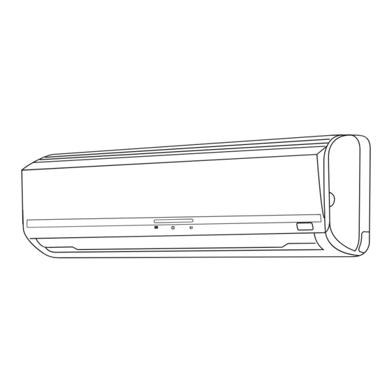
(WALL TYPE)
INDOOR UNIT
RAS-18G5
1 Ø, 50 Hz, 220-230 V
1620-1620
7.70-7.40
5.25-5.25
17,910
1030
295
207
12
NO. 0485E
CONTENTS
OUTDOOR UNIT
RAC-18G5
850
650
298
47
Advertisement
Table of Contents

Related Manuals for Hitachi RAS-18G5


Summary of Contents for Hitachi RAS-18G5
-
Page 1: Table Of Contents
NO. 0485E RAS-18G5/RAC-18G5 SERVICE MANUAL TECHNICAL INFORMATION REFER TO THE FOUNDATION MANUAL FOR SERVICE PERSONNEL ONLY CONTENTS SPECIFICATIONS ------------------------------------------------------ 4 HOW TO USE ---------------------------------------------------------- 6 CONSTRUCTION AND DIMENSIONAL DIAGRAM ---------26 MAIN PARTS COMPONENT --------------------------------------28 WIRING DIAGRAM ---------------------------------------------------30 CIRCUIT DIAGRAM --------------------------------------------------31... - Page 2 SAFETY DURING REPAIR WORK 1. In order to disassemble and repair the unit in question, be sure to disconnect the power cord plug from the power outlet before starting the work. 2. If it is necessary to replace any parts, they should be replaced with respective genuine parts for the unit, and the replacement must be effected in correct manner according to the instructions in the Service Manual of the unit.
- Page 3 WORKING STANDARDS FOR PREVENTING BREAKAGE OF SEMICONDUCTORS 1. Scope The standards provide for items to be generally observed in carrying and handling semiconductors in rela- tive manufacturers during maintenance and handling thereof. (They apply the same to handling of abnormal goods such as rejected goods being returned).
- Page 4 (6) Use a three wire type soldering iron including a grounding wire. Metal plate (of aluminium, stainless steel, etc.) Working table Resistor of 1M (1/2W) Staple Earth wire Bare copper wire (for body earth) Fig. 3. Grounding of the working table Soldering iron Grounding wire...
- Page 5 CAUTION In quiet or stop operation, slight fl owing noise of refrigerant in the refrigerating cycle is heard occasionally, but this noise is not abnormal for the operation. When it thunders near by, it is recommended to stop the operation and to disconnect the power cord plug from the power outlet for safety.
-
Page 6: Specifications
SPECIFICATIONS MODEL RAS-18G5 RAC-18G5 FAN MOTOR 30 W 40 W FAN MOTOR CAPACITOR 2.5μF, 450V FAN MOTOR PROTECTOR YES (INTERNAL) COMPRESSOR – ASH210SV-C8LU COMPRESSOR MOTOR CAPACITOR 60μF, 450VAC OVERLOAD PROTECTOR YES (INTERNAL) OVERHEAT PROTECTOR YES (INTERNAL) 3.15A FUSE (MICRO COMPUTER CIRCUIT) - Page 7 Figure showing the Installation of Indoor and Outdoor Unit In case the pipe length is more than 8m, add refrigerant R410A at 15 gram per every meter exceeds. However, pipe length shall not exceed 15m. CAUTION Be sure to completely seal any gap.
-
Page 8: Names And Functions Of Each Part
OUTDOOR UNIT Drain pipe Condensed water drain to outside. Connecting cord and insulation pipe for piping Air inlet (Back and Left side) Air outlet MODEL NAME AND DIMENSIONS MODEL WIDTH (mm) HEIGHT (mm) DEPTH (mm) RAS-18G5 1030 RAC-18G5 – 6 –... - Page 9 INDOOR UNIT INDICATORS OPERATION LAMP This lamp lights during operation. TIMER LAMP This lamp lights when the timer is working. FILTER LAMP When the device is operated for a total of about 200 hours, the FILTER lamp lights to indicate that it is time to clean the fi...
- Page 10 Note Avoid to use the room air conditioner for cooling operation when the outside temperature is below ● 21°C (70°F). The recommended maximum and minimum operating temperatures of the hot and cold sides should be as below: Minimum Maximum Indoor Dry bulb °C Wet bulb °C Outdoor...
-
Page 11: Safety Precaution
SAFETY PRECAUTION Please read the “Safety Precaution” carefully before operating the unit to ensure correct usage of the unit. ● Pay special attention to signs of “ Warning” and “ Caution”. The “Warning” section contains matters which, ● if not observed strictly, may cause death or serious injury. The “Caution” section contains matters which may result in serious consequences if not observed properly. - Page 12 PRECAUTIONS DURING OPERATION The product shall be operated under the manufacturer specifi cation and ● not for any other intended use. Do not attempt to operate the unit with wet hands, this could cause fatal ● accident. When operating the unit with burning equipments, regularly ventilate the ●...
-
Page 13: Names And Functions Of Remote Control Unit
NAMES AND FUNCTIONS OF REMOTE CONTROL UNIT REMOTE CONTROLLER This controls the operation of the indoor unit. Signal range to reach indoor unit is about 7 meters. If inverter lamp is used, the range of control may be shorter. This unit can be fi xed on a wall using the fi xture provided. Before fi xing it, make sure the indoor unit can be controlled from the remote controller. -
Page 14: Cooling Operation
COOLING OPERATION Use the device for cooling when the outdoor temperature is 21 ~ 43°C. If indoor humidity is very high (over 80%), some dew may form on the air outlet grille of the indoor unit. Press the button so that the display indicates (COOL). -
Page 15: Dehumidifying Operation
DEHUMIDIFYING OPERATION Use the device for dehumidifying when the room temperature is over 16°C. When it is under 15°C, the dehumidifying function will not work. Press the button so that the display indicates (DEHUMIDIFY). Dehumidifying operation starts with a beep. The FAN SPEED is set at LOW automatically. -
Page 16: Circulation Operation
CIRCULATION OPERATION Press the button so that the display indicates (CIRCULATION). Circulating operation starts with a beep. Press the FAN SPEED button and select the desired FAN SPEED (the display indicates your choice). Press the temperature control button to set to the desired temperature. -
Page 17: How To Set The Sleep Timer
HOW TO SET THE SLEEP TIMER Press the (SLEEP) button, and the display changes as shown below. Mode Indication 1 hour 2 hours 3 hours 7 hours Sleep timer Sleep timer off Sleep Timer: The device will continue working for the designated number of hours and then turn off. -
Page 18: How To Set The Timer
HOW TO SET THE TIMER ■ ON Timer and OFF Timer are available. ■ Operation stop at setting time OFF Timer Reservation OFF TIME setting ● Select the OFF TIME by pressing the (OFF) Button. ● Setting time will change according to the below sequence when you press the button. -
Page 19: Adjusting The Air Deflectors
ADJUSTING THE AIR DEFLECTORS Adjustment of the conditioned air in the upward and downward directions. The horizontal air defl ector is automatically set to the proper angle suitable for each operation. The defl ector can be swung up and down continuously and also set to the desired angle using the “... -
Page 20: How To Exchange The Batteries In The Remote Controller
HOW TO EXCHANGE THE BATTERIES IN THE REMOTE CONTROLLER When using the remote control, if there is no response from the air conditioner unit and/or the remote control has fading and dim displays, the batteries in the remote control device need to be removed and replaced with new ones Remove the cover as shown in the fi... - Page 21 THE IDEAL WAYS OF OPERATION Suitable Room Temperature Install curtain or blinds Warning It is possible Freezing temperature to reduce heat is bad for health and a entering the waste of electric power. room through windows. Ventilation Effective Usage Of Timer At night, please use the “OFF or ON timer Caution operation mode”, together with your wake up...
- Page 22 FOR USER’S INFORMATION The Air Conditioner And The Heat Source In The Room Caution If the amount of heat in the room is above the cooling capability of the air conditioner (for example: more people entering the room, using heating equipments and etc.), the preset room temperature cannot be achieved.
-
Page 23: Attaching The Air Purifying Filters
ATTACHING THE AIR PURIFYING FILTERS CAUTION Cleaning and maintenance must be carried out when fi lter lamp lights. Before cleaning, stop operation and switch off the power supply. Open the front panel ● Pull up the front panel by holding it at both sides with both hands. - Page 24 MAINTENANCE CAUTION Cleaning and maintenance must be carried out when fi lter lamp lights. Before cleaning, stop operation and switch off the power supply. 1. PRE-FILTER Clean the pre-fi lter, as it removes dust inside the room. In case the pre-fi lter is full of dust, the air fl...
- Page 25 Washable Front Panel ● Remove the front panel and wash with clean water. Wash it with a soft sponge. After using neutral detergent, wash thoroughly with clean water. ● When front panel is not removed, wipe it with a soft dry cloth. Wipe the remote controller thoroughly with a soft dry cloth.
- Page 26 CAUTION ● Please use earth line. Do not place the earth line near water or gas pipes, lightning-conductor, or the earth line of telephone. Improper installation of earth line may cause electric shock. ● A circuit breaker should be installed depending on the mounting site of the unit. Without a circuit breaker, the danger of electric shock exists.
- Page 27 AFTER SALE SERVICE AND WARRANTY WHEN ASKING FOR SERVICE, CHECK THE FOLLOWING POINTS CONDITION CHECK THE FOLLOWING POINTS ● Is the fuse all right? ● Is the voltage extremely high or low? When it does not operate ● Is the circuit breaker “ON”? ●...
-
Page 28: Construction And Dimensional Diagram
CONSTRUCTION AND DIMENSIONAL DIAGRAM MODEL RAS-18G5 Note: 1. Servicing space of 100mm or more is required on the left and right sides of the indoor unit and also 50mm or more space is required above the unit 2. Insulated pipes should be used for both the narrow and wide dia. pipes. - Page 29 MODEL RAC-18G5 – 27 –...
-
Page 30: Main Parts Component
MAIN PARTS COMPONENT THERMOSTAT Thermostat Specifi cations MODEL RAS-18G5 THERMOSTAT MODEL COOL OPERATION MODE 15.6 (60.1) INDICATION 15.3 (59.5) TEMPERATURE 23.6 (74.5) INDICATION °C (°F) 23.3 (73.9) 31.6 (88.9) INDICATION 31.3 (88.3) FAN MOTOR Fan Motor Specifi cations MODEL RAS-18G5... - Page 31 COMPRESSOR MOTOR Compressor Motor Specifi cations MODEL RAC-18G5 COMPRESSOR MODEL ASH210SV-C8LU PHASE SINGLE RATED VOLTAGE 220 ~ 230 V RATED FREQUENCY 50 Hz LOCKED ROTOR CURRENT 40 A POLE NUMBER CONNECTION 20°C RM = 1.69 (68°F) RA = 1.54 RESISTANCE VALUE 75°C RM = 2.06 (167°F)
- Page 32 – 30 –...
-
Page 33: Circuit Diagram
CIRCUIT DIAGRAM Remote Control – 31 –... -
Page 34: Printed Wiring Board Location Diagram
PRINTED WIRING BOARD LOCATION DIAGRAM MODEL RAS-18G5 – 33 –... - Page 35 – 35 –...
-
Page 36: Basic Mode
BASIC MODE MODEL RAS-18G5/RAC-18G5 Operation mode Cooling Sensor dehumidi cation Circulation Control function ON / OFF switch, basic mode Both operation lamp during Sensor dehumidi cation at OFF timer operation mode. Timer operation ON timer ““HI””, ““MED””, or ““LO”” operation is executed Automatic according to the thermostat signal. - Page 37 Operation mode Cooling Sensor dehumidifi cation Circulation Control function Sleep mode The set temperature ● after sleep shift in sensor dehumidifi cation The operation is switched OFF at the set time. operation is limited ● by 16°C. Notes: 60 minutes after the sleep key is switched on, sleep operation is started. ●...
- Page 38 Table 1 Speci cations (2) Compensation ““room temperature”” is used. Item RAS-18G5 The ““Attained”” state is monitored and a ““Not attained”” check is Automatic done to revise the compensation time (HT). Circulator Operation switching Sensor dehumidi...
-
Page 39: Refrigerating Cycle Diagram
REFRIGERATING CYCLE DIAGRAM MODEL RAS-18G5/RAC-18G5 – 43 –... -
Page 40: Description Of Main Circuit Operation
DESCRIPTION OF MAIN CIRCUIT OPERATION 1. ON / OFF The “ON / OFF” and “Timer reserve button” and “Sleeping” function independently. Their operations are shown in Fig. 1-1. Fig. 1-1 Timer operation – 44 –... - Page 41 2. Reset Circuit The reset circuit is used to reset the program to its initial settings when the power is turned on or when the ● power is recovered after a power failure. The micro computer is reset when the reset input is “Lo”, and operation is possible when the reset input is ●...
- Page 42 3. Buzzer Circuit When the buzzer is to be activated, buzzer output pin of the micro computer alternates between ON and OFF repeatedly at 4kHz and Q302 is turned ON/OFF accordingly. A 4kHz voltage is applied to the buzzer and the diaphragm of the buzzer vibrates to output 4kHz sound. 4.
- Page 43 5. Service Operation Circuit SERVICE SW Use the service switch to select “Cooling” temporarily when the interior electric equipment has troubled. ● Setting the switch to “Cooling” causes continuous cooling room temperature control. To control the room ● temperature, turn on and off the disconnect switch. To protect the compressor, wait at least 3 minutes before turning on again.
- Page 44 – 48 –...
-
Page 45: Service Call Q
SERVICE CALL Q & A Cooling operation While cooling, the compressor sometimes Check whether frost sticks on the heat stops abruptly. exchanger of indoor unit or not. Wait for 3 – 4 minutes until the frost melts. Dehumidifying operation The fan speed does not change during The fan speed is always LO at a dehumidifying a dehumidifying operation. - Page 46 Common, etc. There is a difference between the room There may be a difference between the temperature setting and actual room room temperature setting and actual room temperature. temperature on account of the room structure, air fl ow, etc. If there is a difference from the room temperature, adjust the set temperature to keep living space at a comfortable temperature.
-
Page 47: Trouble Shooting
TROUBLE-SHOOTING No cooling *1 Before using the service switch, disengage No operation at all. and engage the plug. Do not operate the Operates by setting the service remote controller. switch to forced cooling? Check the following parts and replace if faulty 1) Current fuse Remove and check the continuity across. - Page 48 Timer-Lamp, break-down checking in blinking sign. Check the break-down factor from the frequency of timer-lamp blinking. Mode of Timer-Lamp blinking Indication Factor Estimated Break-Down Part Force cooling operation Check force cooling switch at indoor electrical. Unit is under forcible operation –...
-
Page 49: Parts List And Diagram
PARTS LIST AND DIAGRAM INDOOR UNIT MODEL : RAS-18G5 – 53 –... - Page 50 MODEL RAS-18G5 PART N0. Q’TY / UNIT PARTS NAME RAS-18G5 PMRAS-S18CAK R02 CABINET PMRAS-40CNH2 R23 MOUNTING PLATE PMRAS-70YHA FAN MOTOR PMRAS-70YHA TANGENTIAL FLOW FAN PMRAS-25CNH2 005 P-BEARING ASSY PMRAS-51CHA1 004 FAN MOTOR BASE PMRAS-S18CAK R03 CYCLE ASSY PMRAS-51CHA1 R20 FAN COVER...
- Page 51 PARTS LIST AND DIAGRAM OUTDOOR UNIT MODEL : RAC-18G5 – 55 –...
- Page 52 MODEL RAC-18G5 PART N0. Q’TY / UNIT PARTS NAME RAC-18G5 PMRAC-50NH4 SV-COVER PMRAC-S18CAK S01 COMPRESSOR PMRAC-18GH4 COMPRESSOR RUBBER PMRAC-50NH4 VALVE (2S) PMRAC-18GH4 VALVE (4S) PMRAC-63CA1 CONDENSER PMRAC-40CNH2 S18 FAN MOTOR SUPPORT PMRAC-S18CXK 902 FAN MOTOR PMRAC-30CH7 PROPELLER FAN PMRAC-63CA1 TERMINAL BOARD (2P) PMRAC-63CHA2 S07 COMPRESSOR CAPACITOR PMRAC-63CHA2 S08...
- Page 53 PM NO. 0485E RAS-18G5 / RAC-18G5 Made in Malaysia...
Need help?
Do you have a question about the RAS-18G5 and is the answer not in the manual?
Questions and answers