Table of Contents
Advertisement
Quick Links
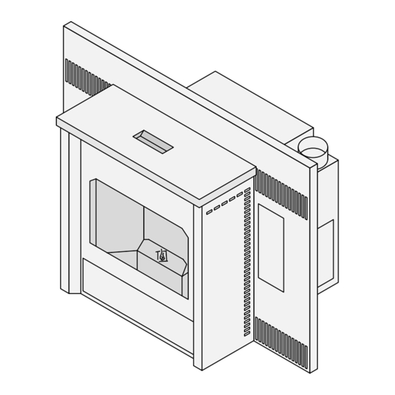
AGP Pellet Insert
-- Please read this entire manual before
installation and use of this pellet fuel-
burning room heater. Failure to follow
these instructions could result in
property damage, bodily injury, or even
death.
-- Contact local building or fire officials
about restrictions and installation
inspection requirements in your area.
-- Save these instructions.
Installer: After installation give this manual to the home-
owner and explain operation of this insert.
Consumer: Retain this manual for future reference.
$10.00
Part # 100-01341
Copyright 2015, T.I.
4141230
Masonry Fireplace
•
•
Factory-Built (Metal)Fireplace
•
Mobile Home Approved
Tested and Listed by:
ASTM E1509-4 ULC-S628
Travis Industries, Inc.
www.travisproducts.com
12521 Harbour Reach Drive
Mukilteo, WA 98275
Advertisement
Table of Contents

Subscribe to Our Youtube Channel
Related Manuals for Travis Industries AGP PI


Summary of Contents for Travis Industries AGP PI
- Page 1 -- Save these instructions. Installer: After installation give this manual to the home- Travis Industries, Inc. owner and explain operation of this insert. www.travisproducts.com Consumer: Retain this manual for future reference.
-
Page 2: Introduction
Do not mail your Bill of Sale to us. Model: AGP PI We suggest that you attach your Bill of Sale to this page so that you will have all the information you need in one place should the need for Serial Number: service or information occur. -
Page 3: Table Of Contents
Replacement Parts ..........46 Manual Mode ............27 Door Parts ............46 To Start ..............27 Wiring Diagram ............47 To Shut Down ............27 Thermostat Installation .......... 51 © Travis Industries 4141230 100-01341... - Page 4 This heater is designed and approved to prevent the possibility of a house for pelletized wood fuel only. fire. The instructions must be strictly adhered to. Do not use makeshift methods or compromise in the installation. © Travis Industries 4141230 100-01341...
- Page 5 NOT BE maintain your heater may lead to INSTALLED IN THE BEDROOM accumulation of soot, creosote, and (per H.U.D. requirements). Check ash, and smoke spillage or fire in with local building officials. your home. © Travis Industries 4141230 100-01341...
- Page 6 Manual instructions that you will need at a later time. Always follow the instructions in this manual. Travis Industries, Inc. grants no The exhaust system should be checked at least twice a year for warranty, implied or stated, for any build-up of soot or creosote.
-
Page 7: Heating Specifications
Watts during Start-Up Sequence ................350 (approximately) Watts during Operation ................... 250 (approximately) Fuel This heater is designed and approved for pelletized wood fuel only (all grades). Emissions 0.66 Grams per Hour (EPA Phase II Approved) © Travis Industries 4141230 100-01341... -
Page 8: Before You Begin
AGP Pellet Insert Side Panels (SKU 94400030, 94400031, or 94400032) Installation Options This insert must be installed into a clean undamaged fireplace . Fireplace must be: Masonry Fireplace (Code-Conforming UBC Masonry Fireplace) - or - Factory Built (Metal) Fireplace © Travis Industries 4141230 100-01341... -
Page 9: Planning The Installation
(For Qualified Installers Only) Planning the Installation HINT: Have an authorized Travis Industries dealer install this heater. If you install the heater yourself, have your dealer review your installation plans. HINT: Inspect the chimney and clean as necessary before installing the heater. NOTE: The convection blower is open to the fireplace cavity and may circulate odors from the fireplace. -
Page 10: Electrical Requirements
Do not route the electrical cord underneath, in front of, or over the heater. HINT: Travis Industries manufactures a Insert Wiring Kit (97200315) that allows the power cord to be routed through the fireplace, concealing the power cord. © Travis Industries... -
Page 11: Hopper Extension Set-Up
The hopper top is shipped attached to the hopper assembly with shipping screws. Follow the instructions below to attach the hopper top to the hopper assembly using the screws included in the owner’s pack. Determine the correct hopper extension based on the table below. Shipping Screw (both sides) © Travis Industries 4141230 100-01341... -
Page 12: Hopper Extension Setup
Place the hopper top over the hopper assembly. Line up the holes in the hopper top with the holes on the hopper assembly. Use the 9 screws included in the owner’s pack to secure the hopper top to the hopper assembly. © Travis Industries 4141230 100-01341... -
Page 13: Clearances
Place the insert so the back edge of the baseplete extends 14-1/4" (362mm) into the fireplace. Run the power cord to the side along the front of the fireplace (do not route it under the insert). © Travis Industries 4141230 100-01341... -
Page 14: Venting The Pellet Insert
The chimney liner must conform to the Class 3 requirements of CAN/ULC-S636, Standard for Lining Systems for Existing Masonry or Factory-Built Chimneys and Vents, or CAN/ULC-S640, Standard for Lining Systems for New Masonry Chimneys. © Travis Industries 4141230 100-01341... -
Page 15: Travis Vent Kits
Installation (For Qualified Installers Only) Travis Vent Kits 20’ Vent Kit 98900052 35’ Vent Kit 98900053 © Travis Industries 4141230 100-01341... -
Page 16: Mobile Home Requirements
Must be made with 1-¾” (45mm) diameter or larger metal or aluminum duct with a metal screen attached to the end to keep out rodents (P.V.C. or other combustible materials may not be used). We recommend the Travis Industries Outside Air Kit (part # 99200136 – additional duct may be required). -
Page 17: Detachable Vent Connector
(4) sheet metal screws. Apply additional RTV silicone to the area around the connection to ensure an air-tight seal. NOTE: All vent connections should be made with the tapered section facing downwards (see photos below). © Travis Industries 4141230 100-01341... -
Page 18: Restrictor Adjustment
Follow the directions below to adjust the restrictor to the closed position. To adjust the restrictor to closed position: a) Remove the burn platform. b) Loosen the two screws. c) Slide the restrictor down. d) Tighten the screws. © Travis Industries 4141230 100-01341... -
Page 19: Surround Panel & Control Panel Installation & Removal
– skip to step 5).. Each side panel is held in place with two screws (see photo below, to the left). Use a phillips screwdriver to loosen these screws 2 turns. 2 Turns 2 Screws Hold Side Panel in Place © Travis Industries 4141230 100-01341... - Page 20 4. Slide each side panel forward and place aside. The side panels have slots that fit over the screws. NOTE: When re-installing the side panel, make sure the tabs on the panel insert into the slots on the front of the insert © Travis Industries 4141230 100-01341...
- Page 21 6. Carefully slide the surround panel over the hopper lid, taking care to prevent scratching. When sliding the panel into place, lift up on the panel to prevent scratching (use plastic from the stove packaging to prevent scratching). © Travis Industries 4141230 100-01341...
- Page 22 Double-check panel alignment to verify all hooks have engaged. Hooks 8. Slide the insert into place, making sure to protect the hearth. 9. Attach the side panels (see steps 3 and 4). © Travis Industries 4141230 100-01341...
-
Page 23: Installation Into A Masonry Fireplace
Seal the cover plate with silicone. “L” Vent Flex Section HINT: Paint the interior of the fireplace with latex paint to prevent fireplace odors from entering the home. Outside air may be drawn from the ash cleanout. © Travis Industries 4141230 100-01341... -
Page 24: Installation Into A Factory-Built (Metal) Fireplace
You may remove the leveling bolts and structural components of the factory built be removed leaving he fireplace attach telescoping legs to support the fireplace may not be removed or altered. floor outer wrap. insert on raised fireplaces. © Travis Industries 4141230 100-01341... -
Page 25: Safety Notice
DO NOT USE CHEMICALS OR FLAMMABLE FLUIDS TO START THIS HEATER. Location of Controls The control panel is located on the right panel, behind an access door. Open the access door to access the controls. © Travis Industries 4141230 100-01341... -
Page 26: Loading Pellets
Open doors and windows to the room to vent these fumes. You may also notice oil burning off of the interior of the insert. This rust- stopping agent will soon dissipate. Allow 48 hours for the paint to cure. © Travis Industries 4141230 100-01341... -
Page 27: Manual Mode
45 minutes. To Adjust the Heat Turn the HEAT knob on the control panel to the left (lower heat) or right (higher heat). The HEAT knob adjusts the rate of pellets feeding into the insert. © Travis Industries 4141230 100-01341... -
Page 28: To Adjust The Fan
Auto-Fan Turn the FAN knob to the AUTO-FAN setting on the control panel to automatically adjust the fan speed based on the feed rate into the hopper. This allows for more efficient operation. © Travis Industries 4141230 100-01341... -
Page 29: Tstat (Thermostat) Mode
(or to low) once the thermostat setting is met. Wireless thermostats are available from Travis Industries. See your dealer for details. To Start the Insert in TSTAT Mode Press the TSTAT button on the control panel. -
Page 30: Changing The Tstat Program
Heater runs at setting set Heater will run for 15 minutes. If thermostat still on control panel dial. open, heater turns off. NOTE: This program is not recommended for areas with little heating requirements (mild climates, small rooms, etc.). © Travis Industries 4141230 100-01341... -
Page 31: Thermostat Program 2
CLOSED TO KEEP THE POSSIBILITY OF SMOKE SPILLAGE TO A MINIMUM. NOTE: Travis Industries recommends a minimum vertical vent of 5’ to ensure adequate draft during a power outage. NOTE: The exhaust blower will start and run up to 20 minutes every time power is interrupted (or the power cord is unplugged and plugged in). -
Page 32: Insert Maintenance
If the ashes are disposed of by burial in soil or otherwise locally dispersed, they should be retained in the closed container until all cinders have been thoroughly cooled. © Travis Industries 4141230 100-01341... -
Page 33: Insert Maintenance Tools
(ashes that solidify into a clump). The most likely causes of clinkers are: Poor pellet quality The door or glass has an air leak The exhaust system requires cleaning © Travis Industries 4141230 100-01341... -
Page 34: Cleaning The Fire Platform
Slide the the visual deflector to the left while lifting from the right. Once the pin disengages from the visual deflector on the left side, the visual deflector may be removed from the firebox. © Travis Industries 4141230 100-01341... - Page 35 3. Use the cleaning tool to scrape away hardened clinkers or buildup on the fire platform. Use the narrow tip to clear any plugged holes. The fire platform must be free from buildup for the pellets to burn completely. © Travis Industries 4141230 100-01341...
- Page 36 4. Brush away flyash around the fire platform using the brush included with the insert. The flyash will fall into the ashpan below. Brush the flat surfaces to remove flyash Lift the fire platform out of the firebox and remove any flyash below the burn platform. © Travis Industries 4141230 100-01341...
-
Page 37: Cleaning The Heat Exchange Tubes
2. Hook the cleaning tool onto the heat exchange scraper rod as shown below. 3. Move the scraper rod back and forth a few times to clean the heat exchange tubes. ( NOTE: Door must be shut while cleaning the heat exchange tubes. © Travis Industries 4141230 100-01341... -
Page 38: Cleaning The Glass
2. Remove the ashpan from the appliance and properly dispose of the ashes (see “Disposal of Ashes” on page 32 for details). NOTE: Make sure the ashpan is pushed in 100% when replaced (this allows for full flyash coverage). © Travis Industries 4141230 100-01341... -
Page 39: Cleaning Behind The Firebox Liners
To remove, lift it up and slide it out. 3. Remove the side liners. They have keyhole slots that fit over screws on the side of the firebox. Lift them up, tilt them inwards, then remove. © Travis Industries 4141230 100-01341... -
Page 40: Cleaning The Exhaust Duct
1. Open the door. 2. Remove the ashpan. 3. Remove the two exhaust duct covers as shown below. 4. Use a brush or vacuum cleaner to clean out the exhaust ducts and the area inside the firebox. © Travis Industries 4141230 100-01341... -
Page 41: Access And Clean Components
1. Remove the insert from the fireplace (see above). 2. Loosen the 8 screws holding the intake duct cover in place (11/32” nutdriver). Remove the intake duct cover by sliding it up and off the studs (the gasket will remain in place). © Travis Industries 4141230 100-01341... - Page 42 (the gasket will remain in place). 4. Clean the exhaust blower with a bottle brush or vacuum. NOTE: Take care to prevent damaging the combustion blower impellers. © Travis Industries 4141230 100-01341...
-
Page 43: Cleaning The Convection Blower
NOTE: Do not over-tighten the wingnuts when replacing (the rubber grommets must flex to absorb vibrations). Remove the 2 Wingnuts Remove all dust and debris from the convection blower. NOTE: Take care to prevent damaging the convection blower impellers. © Travis Industries 4141230 100-01341... -
Page 44: Cleaning The Negative Pressure Tube
While open, use a flashlight to look up the vent to check for build-up. WHENEVER ANY PORTION OF THE PELLET VENT IS DISCONNECTED, THE JOINTS MUST BE SEALED WITH RTV 500° F. SILICONE SEALANT, UNLESS OTHERWISE SPECIFIED BY THE VENT MANUFACTURER. © Travis Industries 4141230 100-01341... -
Page 45: Adjusting The Door Cam
Open the ashpan access door and inspect the gasket around the door. Re-attach or replace the gasket if necessary. Re-attach, or replace the gasket if necessary. NOTE: Ask your authorized Travis dealer to demonstrate how to check a door seal. © Travis Industries 4141230 100-01341... -
Page 46: Troubleshooting Table
NOTE: Always check to make sure pellets are in the hopper and the fire platform is clean. Replacement Parts Contract your Travis Industries Dealer for replacement parts. Use only replacement parts from Travis Industries designed specifically for this heater. Door Parts... -
Page 47: Wiring Diagram
Safety Snap Disc Snap Disc 200° NC 200° NC Encoder Molex Exhaust Blower Hopper Lid Flow Switch Switch Convection Metering Push Blower Power Cord Auger Motor Auger Motor Ground Igniter Common 1077 White White White © Travis Industries 4141230 100-01341... - Page 48 EXTENSION material underneath appliance. U.S. ENVIRONMENTAL PROTECTION AGENCY: Certified to comply with July 1990 particulate emission standards. DATE OF MANUFACTURE 2013 2014 2015 Jan. Feb. Mar. Apr. June July Aug. Sep. Oct. Nov. Dec. 1056 © Travis Industries 4141230 100-01341...
- Page 49 16. If for any reason any section of this warranty is declared invalid, the balance of the warranty remains in effect and all other clauses shall remain in effect. 17. This 7 year warranty is the only warranty supplied by Travis Industries, Inc., the manufacturer of the appliance. All other warranties, whether express or implied, are hereby expressly disclaimed and purchaser’s recourse is expressly limited to the warranties set forth herein.
- Page 50 At that time, you may be asked to ship your appliance, freight charges prepaid, to TRAVIS INDUSTRIES, INC. TRAVIS INDUSTRIES, INC., at its option, will repair or replace, free of charge, your appliance if it is found to be defective in material or workmanship within the time frame stated within this 7 year warranty.
-
Page 51: Thermostat Installation
(orientation does not matter). Make sure the wires do not contact hot or moving components. See the instructions included with the thermostat for further details. © Travis Industries 4141230 100-01341... - Page 52 Heating Specifications ........7 Venting the Pellet Insert ........14 Hopper Extension Set-up ......... 11 Yearly Maintenance - Clean the Negative Important Information ......... 2 Pressure Tube ..........44 Insert Maintenance ........... 32 Insert Maintenance Tools ......... 33 © Travis Industries 4141230 100-01341...
Need help?
Do you have a question about the AGP PI and is the answer not in the manual?
Questions and answers