Monogram ZV48R Installation Instructions Manual
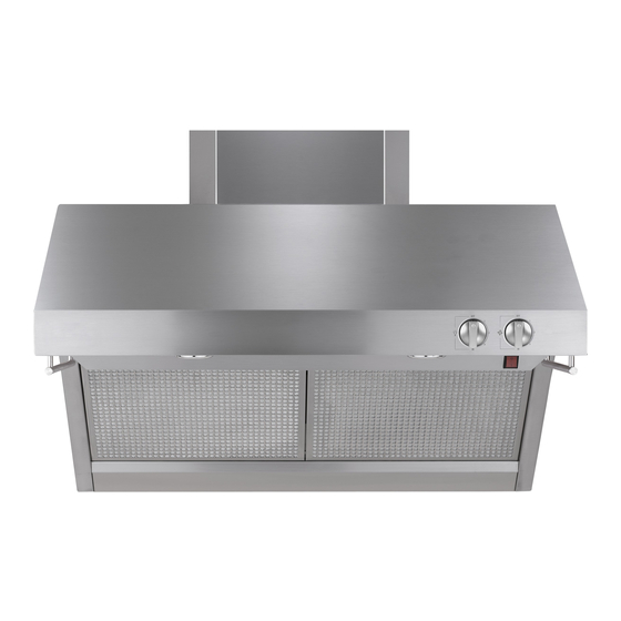
30", 36" and 48" professional restaurant style vent hoods
Hide thumbs
Also See for ZV48R:
- Installation instructions manual (32 pages) ,
- Installation instructions manual (16 pages) ,
- Installation instructions manual (18 pages)

Related Manuals for Monogram ZV48R


Summary of Contents for Monogram ZV48R
- Page 1 Installation Instructions If you have questions, call 800.GE.CARES or visit our website at: www.monogram.com 30", 36" and 48" Professional Restaurant Style Vent Hoods Models: ZV48R ZV36R ZV30R...
-
Page 2: Installation Instructions
Installation Instructions BEFORE YOU BEGIN WARNING: TO REDUCE THE RISK OF FIRE, ELECTRICAL SHOCK OR Read these instructions completely and carefully. INJURY TO PERSONS, OBSERVE THE FOLLOWING: • I MPORTANT - Save these instructions for local A. Use this unit only in the manner intend ed by the inspector’s use. -
Page 3: Table Of Contents
Hoods may be Warming installed with the Shelf shelf or back- guard alone, u a r d or with both as B a c k g shown. Model ZV48R Model ZV36R Model ZV30R... -
Page 4: Installation Clearances
6" Duct Cover Soffit Installation 12" Duct Cover SO FF IT SO FF IT 6" Duct Covers Hood Model 6” Duct Cover Dimensions 30" Min. 32" Min. ZV48R ZX48DC6 6"H x 19-11/16"W x 11-7/8"D 36" Max. 38" Max. ZV36R ZX36DC6 6"H x 15-3/4"W x 11-7/8"D ZV30R ZX36DC6 6"H x 15-3/4"W x 11-7/8"D 12"... -
Page 5: Installation Height, Duct Cover Accessories
Advance Planning DETERMINE INSTALLATION HEIGHT, DUCT COVER ACCESSORIES These vent hoods must be installed 30" min. to Restaurant-Style Hoods Restaurant-Style Hoods with 36" max. above the standard 36" high cook- without Warming Shelf Shelf Installed ing surface. When installed with the warming Installed shelf, allow 32" min. to 38" max. clearance. The *Possible *Possible Actual 6" 12" 6" 12" exact hood installation height is determined Hood Hood Ceiling Duct Duct Duct... -
Page 6: Advance Planning
Advance Planning ADVANCE PLANNING POWER SUPPLY IMPORTANT - (Please read carefully) Ductwork Planning WARNING: • These vent hoods are equipped for 10" round ductwork. For best performance, use 10" round ductwork on the FOR PERSONAL SAFETY, THIS APPLIANCE MUST BE PROP- 48" wide hoods. 30" and 36" hoods may be transitioned ERLY GROUNDED. to 8" round. AVERTISSEMENT – • This hood may be vented vertically through upper cabi- POUR DES RAI- nets, soffit or ceiling. A duct transition piece is supplied SONS DE SÉCURITÉ, CET APPAREIL DOIT ÊTRE CORRECTE- for vertical exhaust. Use locally supplied elbows to vent MENT MIS À LA TERRE. horizontally through the rear wall. • Determine the exact location of the vent hood. Remove house fuse or open circuit breaker before begin- • Plan the route for venting exhaust to the outdoors. ning installation. • Use the shortest and straightest duct route possible. -
Page 7: Duct Fittings
Advance Planning Equivalent Quantity Total DUCT FITTINGS Duct Piece Length* Used Length Use this chart to compute maximum 10" round permissable lengths for duct runs to to 8" round 5 ft. outdoors. Round, 1 ft. For best results, use 10" diameter duct. straight (per foot length) Note: Do not exceed maximum permissable 8" Dia. 17 ft. equivalent lengths! 90° elbow 10" Dia. 24 ft. Maximum recommended duct length for these hoods: 150 feet 8" Dia. 10 ft. -
Page 8: Tools And Materials Required
Installation Preparation TOOLS AND MATERIALS REQUIRED (NOT SUPPLIED) Hammer Duct tape Electric or battery operated Key Hole Saw Wire cutter/ drill and 1/8", 3/8" bits stripper Duct Tape 10" round Pencil and tape measure 762Dia5 Wire Cutter/Stripper metal duct, Key Hole Saw length to Safety glasses Wire nuts suit installation. Phillips and flat Spirit level blade screwdrivers... -
Page 9: Parts Provided
Installation Preparation PARTS PROVIDED Locate the parts packed with the hood. Wood Support Duct Transition with Original Screws with Damper 2 Stainless Steel Grease Filters (3 filters with 48" models) Heat Lamp 761Dia28 (2 with 48" models) 490Dia66 2 Implement Rods and 4 Stand-offs Backguard Allen Wrench 761Dia30 Grease Tray For Implement Rods Warming Shelf 490Dia57 HARDWARE PACKAGE 4 Phillips head screws to secure the transition to Locate and check con- the hood outlet on the top tents. -
Page 10: Step 1, Determine Ductwork And Wiring Locations
Installation Instructions STEP 1 DETERMINE HOOD, DUCTWORK AND WIRING LOCATIONS • Use a level to draw the cooktop centerline location. Draw the line to ceiling height. 9-7/8" • Measure desired distance from the bottom of the hood to the cooking surface. Top of Hood Note: If you are installing the hood with duct covers, be sure to read “Using Duct Cover Accessories” page 7. Exact installation Wood height may be determined by use of one or more duct covers. -
Page 11: Step 2A Install Hood Onto Wall
Installation Instructions STEP 2A INSTALL HOOD ONTO WALL IMPORTANT: Framing must be capable of supporting up to 150 lbs. Install Transition Onto Top of Hood SKIP THIS STEP IF INSTALLING BENEATH A SOFFIT OR CABINET, GO TO STEP 2B. • Locate at least 2 vertical studs at the wood support. Duct • Center the supplied wood support, left to right and below the Transition... -
Page 12: Step 2B, Install Hood Beneath Soffit
“A” Centerline “B” Hood If Bottom Is Recessed to Stud and Width At Keyhole Slots the Top Push Back Back to Wall ZV48R 23-9/16" 47-15/16" Wall ZV48R 17-9/16" 35-15/16" ZV36R 14-9/16" 29-15/16" Top View • Drive mounting screws into the studs until they protrude Front of Hood 2" 1/4". The 1/4" gap will provide clearance to engage the 8-1/8"... -
Page 13: Step 3 Connect Ductwork
Installation Instructions STEP 5 INSTALL DUCT COVERS STEP 3 CONNECT DUCTWORK • Install ductwork, making connections in direction of Note: For easier handling, remove cardboard insert after airflow as illustrated. film is peeled off. • Secure joints in ductwork with sheetmetal screws. • Wrap all duct joints Remove protective film from duct covers. If more than with duct tape for one duct cover is used, secure each piece together with an airtight seal. screws provided. • Use duct tape to • Place the duct cover(s) on top of the hood. seal the flange Air Flow • From inside the hood, secure the duct cover to the top... -
Page 14: Step 7 Install Filters
Installation Instructions STEP 7 INSTALL FILTERS • Insert the grease filter into the opening and drop into • Drop grease tray into the hood. The rear tabs should the bottom. Raise filter to the top and lock into place. engage the slots in the hood track. • To remove the filters, grasp the handle, push the filter up and lift out. STEP 8 INSTALL BACKGROUND AND SHELF This hood can be installed with the warming shelf and backguard together or with the warming shelf or backguard alone. INSTALL BACKGUARD: INSTALL SHELF OVER BACKGUARD: • Remove packaging. -
Page 15: Step 9, Install Shelf Only
Installation Instructions STEP 9 INSTALL SHELF "ONLY" STEP 10 INSTALL IMPLEMENT RODS • Remove shelf packaging and protective film. • If installing the shelf alone, without the backguard, place shelf against the bottom of the hood and mark the screw hole locations "B" on the wall. • Drill two 1/8" pilot holes. • If the drill did not enter the studs, enlarge holes to 3/8". • Insert the wall anchors into the enlarged holes. Remove the screws from the wall anchors. Screw • Install 2 shoulder screws into holes "D" in the bottom of Stand-offs the hood flange leaving 1/8" gap. Into • Engage shoulder screws into the key hole slots in the top Hood of the shelf. - Page 16 Note: While performing installations described in this book, safety glasses or goggles should be worn. For Monogram local service in your area, call ® 1.800.444.1845. Note: Product improvement is a continuing endeavor at General Electric. Therefore, materials, appearance and specifications are subject to change without notice. Pub. No. 49-80152-5 GE Consumer & Industrial GE Appliances...
Need help?
Do you have a question about the ZV48R and is the answer not in the manual?
Questions and answers