JVC dla-x3 User Manual
Hide thumbs
Also See for dla-x3:
- Instructions manual (79 pages) ,
- Firmware update instructions (6 pages) ,
- Remote control manual (25 pages)
Table of Contents
Advertisement
1
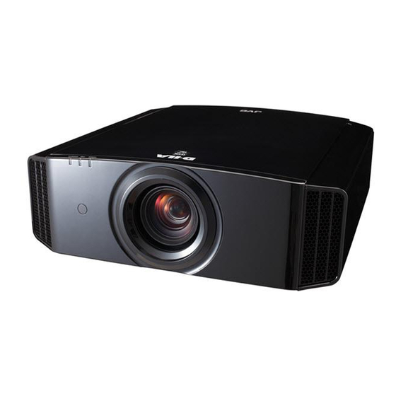
Controls and features
Main body - Front
③ Indicator
STANDBY/ON
LAMP
④ Exhaust Vent
① Lens
This is a projection lens. Please do not look
inside during projection.
② Remote receiver (front)
Please aim the remote control at this area when
using it.
* There is also a remote receiver at the rear.
Main body - Bottom
⑤ Inlets ⑥ Manual button for
14
Getting started
WARNING
lens cover
⑦ Feet
① Lens
② Remote receiver (front)
③ Indicator
Please see "About the indicator display" for
details. (Reference page: 16)
④ Exhaust Vent
Warm air flows out in order to cool the interior of
the set. Please do not block the vents.
⑤ Inlets (at 3 points on the rear/
bottom)
In order to cool the inside of the unit, air is let
inside. Do not block or prevent the outflow of
hot air. Doing so could lead to failure of the unit.
* There are inlets at two points on the right and
left sides of the rear side. (Reference page: 15)
⑥ Manual operation button of the
lens cover
The lens cover can be opened when pressed
down.It is used for maintenance and not used
during normal use.
⑦ Feet
The height (0 to 5 mm) can be adjusted by
turning the foot.
④ Exhaust
Vent
Advertisement
Table of Contents


Need help?
Do you have a question about the dla-x3 and is the answer not in the manual?
Questions and answers