
Related Manuals for Daikin SiBE07-618_D


Summary of Contents for Daikin SiBE07-618_D
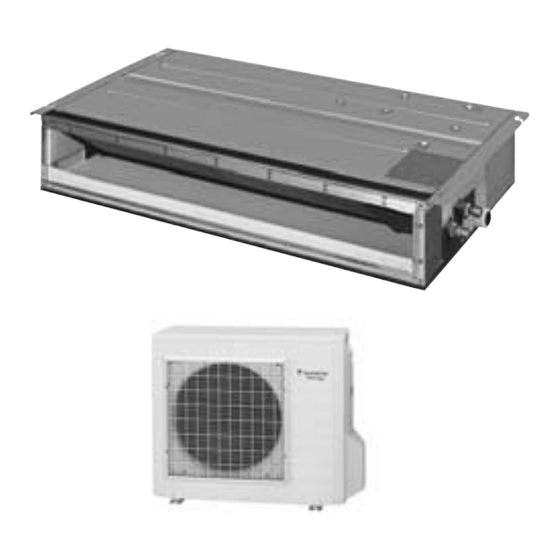
- Page 1 SiBE07-618_D Service Manual Inverter Pair Duct Connected Type C-Series [Applied Models] ● Inverter Pair : Cooling Only ● Inverter Pair : Heat Pump...
- Page 2 SiBE07-618_D Inverter Pair Duct Connected Type C-Series Cooling Only Indoor Unit FDKS50CVMB FDKS60CVMB Outdoor Unit RKS50E2(3)V1B RKS50F2V1B RKS50G2V1B RKS60E2(3)V1B RKS60F2(3)V1B Heat Pump Indoor Unit FDXS50CVMB FDXS60CVMB Outdoor Unit RXS50E2(3)V1B RXS50F2V1B RXS50G2V1B RXS60E2(3)V1B RXS60F2(3)V1B Table of Contents...
-
Page 3: Table Of Contents
SiBE07-618_D 1. Introduction .....................v 1.1 Safety Cautions ..................v 1.2 Used Icons ....................ix Part 1 List of Functions ..............1 1. Functions....................2 Part 2 Specifications ..............5 1. Specifications ..................6 1.1 Cooling Only.....................6 1.2 Heat Pump ....................9 Part 3 Printed Circuit Board Connector Wiring Diagram ... 12 1. - Page 4 SiBE07-618_D 2.2 AUTO · DRY · COOL · HEAT · FAN Operation ........45 2.3 POWERFUL Operation ................47 2.4 OUTDOOR UNIT QUIET Operation............48 2.5 HOME LEAVE Operation ...............49 2.6 TIMER Operation ...................51 Part 6 Service Diagnosis............. 53 1. Caution for Diagnosis................54 1.1 Troubleshooting with LED ..............54...
- Page 5 SiBE07-618_D Part 8 Trial Operation and Field Settings......... 126 1. Pump Down Operation................127 2. Forced Cooling Operation Mode ............128 3. Trial Operation ..................129 4. Field Settings ..................130 4.1 When 2 Units are Installed in 1 Room..........130 4.2 Facility Setting Switch (cooling at low outdoor temperature)....131 4.3 Jumper and Switch Settings..............131...
-
Page 6: Introduction
Introduction SiBE07-618_D 1. Introduction Safety Cautions Cautions and Be sure to read the following safety cautions before conducting repair work. The caution items are classified into “ Warning” and “ Caution”. The “ Warning” Warnings items are especially important since they can lead to death or serious injury if they are not followed closely. - Page 7 SiBE07-618_D Introduction Warning Be sure to wear a safety helmet, gloves, and a safety belt when working at a high place (more than 2 m). Insufficient safety measures may cause a fall accident. In case of R-410A refrigerant models, be sure to use pipes, flare nuts and tools for the exclusive use of the R-410A refrigerant.
- Page 8 Introduction SiBE07-618_D 1.1.2 Cautions Regarding Safety of Users Warning Be sure to use parts listed in the service parts list of the applicable model and appropriate tools to conduct repair work. Never attempt to modify the equipment. The use of inappropriate parts or tools may cause an electrical shock, excessive heat generation or fire.
- Page 9 SiBE07-618_D Introduction Warning Check to make sure that the power cable plug is not dirty or loose, then insert the plug into a power outlet securely. If the plug has dust or loose connection, it may cause an electrical shock or fire.
-
Page 10: Used Icons
Introduction SiBE07-618_D Caution Be sure to measure the insulation resistance after the repair, and make sure that the resistance is 1 MΩ or higher. Faulty insulation may cause an electrical shock. Be sure to check the drainage of the indoor unit after the repair. -
Page 11: Part 1 List Of Functions
SiBE07-618_D Part 1 List of Functions 1. Functions....................2 List of Functions... -
Page 12: Functions
Functions SiBE07-618_D 1. Functions Category Functions Category Functions Basic Inverter (with Inverter Power Control) Health & Air-Purifying Filter — — Function Clean –10 –10 Operation Limit for Cooling (°CDB) Photocatalytic Deodorizing Filter — — ~46 ★ –15 Air-Purifying Filter with Photocatalytic Operation Limit for Heating (°CWB) - Page 13 SiBE07-618_D Functions Category Functions Category Functions Basic Inverter (with Inverter Power Control) Health & Air-Purifying Filter — — Function Clean –10 –10 Operation Limit for Cooling (°CDB) Photocatalytic Deodorizing Filter — — ~46 ★ –15 Air-Purifying Filter with Photocatalytic Operation Limit for Heating (°CWB) —...
- Page 14 Functions SiBE07-618_D Category Functions Category Functions Basic Inverter (with Inverter Power Control) Health & Air-Purifying Filter — — Function Clean –10 –10 Operation Limit for Cooling (°CDB) Photocatalytic Deodorizing Filter — — ~46 ★ –15 Air-Purifying Filter with Photocatalytic Operation Limit for Heating (°CWB) —...
-
Page 15: Part 2 Specifications
SiBE07-618_D Part 2 Specifications 1. Specifications ..................6 1.1 Cooling Only.....................6 1.2 Heat Pump ....................9 Specifications... -
Page 16: Specifications
Specifications SiBE07-618_D 1. Specifications Cooling Only 50 Hz, 230 V Indoor Units FDKS50CVMB FDKS60CVMB Models Outdoor Units RKS50E2(3)V1B RKS60E2(3)V1B 5.0 (2.0 ~ 5.3) 6.0 (2.0 ~ 6.5) Capacity Rated (Min. ~ Max.) Btu/h 17,100 (6,800 ~ 18,100) 20,500 (6,800 ~ 22,200) - Page 17 SiBE07-618_D Specifications 50 Hz, 230 V Indoor Units FDKS50CVMB FDKS60CVMB Models Outdoor Units RKS50F2V1B RKS60F2V1B 5.0 (1.7 ~ 5.3) 6.0 (1.7 ~ 6.5) Capacity Rated (Min. ~ Max.) Btu/h 17,100 (5,800 ~ 18,100) 20,500 (5,800 ~ 22,200) kcal/h 4,300 (1,460 ~ 4,560)
- Page 18 Specifications SiBE07-618_D 50 Hz, 230 V Indoor Units FDKS50CVMB FDKS60CVMB Models Outdoor Units RKS50G2V1B RKS60F3V1B 5.0 (1.7 ~ 5.3) 6.0 (1.7 ~ 6.5) Capacity Rated (Min. ~ Max.) Btu/h 17,100 (5,800 ~ 18,100) 20,500 (5,800 ~ 22,200) kcal/h 4,300 (1,460 ~ 4,560)
-
Page 19: Heat Pump
SiBE07-618_D Specifications Heat Pump 50 Hz, 230 V Indoor Units FDXS50CVMB FDXS60CVMB Models RXS50E2(3)V1B RXS60E2(3)V1B Outdoor Units Cooling Heating Cooling Heating 5.0 (2.0 ~ 5.3) 5.8 (2.0 ~ 6.0) 6.0 (2.0 ~ 6.5) 7.0 (2.0 ~ 8.0) Capacity Rated (Min. ~ Max.) - Page 20 Specifications SiBE07-618_D 50 Hz, 230 V Indoor Units FDXS50CVMB FDXS60CVMB Models RXS50F2V1B RXS60F2V1B Outdoor Units Cooling Heating Cooling Heating 5.0 (1.7 ~ 5.3) 5.8 (1.7 ~ 6.0) 6.0 (1.7 ~ 6.5) 7.0 (1.7 ~ 8.0) Capacity Rated (Min. ~ Max.)
- Page 21 SiBE07-618_D Specifications 50 Hz, 230 V Indoor Units FDXS50CVMB FDXS60CVMB Models RXS50G2V1B RXS60F3V1B Outdoor Units Cooling Heating Cooling Heating 5.0 (1.7 ~ 5.3) 5.8 (1.7 ~ 6.0) 6.0 (1.7 ~ 6.5) 7.0 (1.7 ~ 8.0) Capacity Rated (Min. ~ Max.)
-
Page 22: Part 3 Printed Circuit Board Connector Wiring Diagram
SiBE07-618_D Part 3 Printed Circuit Board Connector Wiring Diagram 1. Printed Circuit Board Connector Wiring Diagram........13 1.1 Indoor Unit....................13 1.2 Outdoor Unit ...................15 Printed Circuit Board Connector Wiring Diagram... -
Page 23: Printed Circuit Board Connector Wiring Diagram
SiBE07-618_D Printed Circuit Board Connector Wiring Diagram 1. Printed Circuit Board Connector Wiring Diagram Indoor Unit Connectors and PCB(1): Control PCB Other Parts 1) S1 Connector for AC fan motor 2) S7 Connector for AC fan motor (Hall IC) 3) S21... - Page 24 Printed Circuit Board Connector Wiring Diagram SiBE07-618_D PCB Detail PCB (1): Control PCB LED A 2P131149-1 PCB (2): Display PCB LED3 LED2 RTH1 LED1 2P084375-1 Printed Circuit Board Connector Wiring Diagram...
-
Page 25: Outdoor Unit
SiBE07-618_D Printed Circuit Board Connector Wiring Diagram Outdoor Unit Connectors and PCB (1): Main PCB Other Parts 1) S10 Connector for terminal board (indoor - outdoor transmission) 2) S20 Connector for electronic expansion valve coil 3) S40 Connector for overload protector... - Page 26 Printed Circuit Board Connector Wiring Diagram SiBE07-618_D PCB Detail PCB (1): Main PCB AC1 E1 (3.15A) (30A) S101 2P169046-1 (3.15A) 2P169046-5 2P169046-7 PCB (2): Service Monitor PCB LED A SW4-B SW4-C S102 3P169059-1 Printed Circuit Board Connector Wiring Diagram...
-
Page 27: Part 4 Function And Control
SiBE07-618_D Part 4 Function and Control 1. Main Functions..................18 1.1 Temperature Control ................18 1.2 Frequency Principle................18 1.3 Fan Speed Control for Indoor Units............20 1.4 Program Dry Operation ................21 1.5 Automatic Operation................22 1.6 Thermostat Control.................23 1.7 NIGHT SET Mode ..................24 1.8 HOME LEAVE Operation ...............25 1.9 Inverter POWERFUL Operation .............26... -
Page 28: Main Functions
Main Functions SiBE07-618_D 1. Main Functions Temperature Control Definitions of The definitions of temperatures are classified as following. Temperatures Room temperature: temperature of lower part of the room Set temperature: temperature set by remote controller Room thermistor temperature: temperature detected by room temperature thermistor... - Page 29 SiBE07-618_D Main Functions Drawing of The following drawing shows a schematic view of the inverter principle: Inverter Refrigerant circulation rate (high) high speed Amount of heat Amount of heat exchanged air (large) exchanged air (large) high f low f Amount of heat...
-
Page 30: Fan Speed Control For Indoor Units
Main Functions SiBE07-618_D Fan Speed Control for Indoor Units Outline Phase control and fan speed control contains 9 steps: LLL, LL, SL, L, ML, M, MH, H, and HH. The airflow rate can be automatically controlled depending on the difference between the room thermistor temperature and the target temperature. -
Page 31: Program Dry Operation
SiBE07-618_D Main Functions Program Dry Operation Outline Program dry operation removes humidity while preventing the room temperature from lowering. Since the microcomputer controls both the temperature and airflow rate, the temperature adjustment and fan adjustment buttons are inoperable in this mode. -
Page 32: Automatic Operation
Main Functions SiBE07-618_D Automatic Operation Outline Automatic Cooling / Heating Function When the AUTO mode is selected with the remote controller, the microcomputer automatically determines the operation mode as cooling or heating according to the room temperature and the set temperature at start-up, and automatically operates in that mode. -
Page 33: Thermostat Control
SiBE07-618_D Main Functions Thermostat Control Thermostat control is based on the difference between the room thermistor temperature and the target temperature. Thermostat OFF Condition The temperature difference is in the zone A. Thermostat ON Condition The temperature difference returns to the zone C after being in the zone A. -
Page 34: Night Set Mode
Main Functions SiBE07-618_D NIGHT SET Mode Outline When the OFF timer is set, the NIGHT SET Mode is automatically activated. The NIGHT SET Mode keeps the airflow rate setting. Detail The NIGHT SET Mode continues operation at the target temperature for the first one hour, then automatically raises the target temperature slightly in the case of cooling, or lowers it slightly in the case of heating. -
Page 35: Home Leave Operation
SiBE07-618_D Main Functions HOME LEAVE Operation Outline HOME LEAVE operation is a function that allows you to record your favorite set temperature and airflow rate. You can start your favorite operation mode simply by pressing the [HOME LEAVE] button on the remote controller. -
Page 36: Inverter Powerful Operation
Main Functions SiBE07-618_D Inverter POWERFUL Operation Outline In order to exploit the cooling and heating capacity to full extent, operate the air conditioner by increasing the indoor fan rotating speed and the compressor frequency. Detail When POWERFUL button is pressed, the fan speed and target temperature are converted to the following states for 20 minutes. -
Page 37: Other Functions
SiBE07-618_D Main Functions 1.10 Other Functions 1.10.1 Hot-Start Function In order to prevent the cold air blast that normally comes when heating operation is started, the temperature of the indoor heat exchanger is detected, and either the airflow is stopped or is made very weak thereby carrying out comfortable heating of the room. -
Page 38: Function Of Thermistor
Function of Thermistor SiBE07-618_D 2. Function of Thermistor Four way valve Compressor (R11582) A Outdoor Heat 1. The outdoor heat exchanger thermistor is used for controlling target discharge pipe temperature. The system sets the target discharge pipe temperature according to the... -
Page 39: Control Specification
SiBE07-618_D Control Specification 3. Control Specification Mode Hierarchy Outline There are two modes; the one is the normal operation mode and the other is the forced operation mode for installation and providing service. Detail For Cooling Only Model There are following modes; stop and cooling (including drying). -
Page 40: Frequency Control
Control Specification SiBE07-618_D Frequency Control Outline Frequency is determined according to the difference between the room thermistor temperature and the target temperature. The function is explained as follows. 1. How to determine frequency 2. Frequency command from the indoor unit (Difference between the room thermistor temperature and the target temperature) 3. - Page 41 SiBE07-618_D Control Specification 2. Determine upper limit frequency The minimum value is set as an upper limit frequency among the frequency upper limits of the following functions: Compressor protection, input current, discharge pipe temperature, heating peak-cut, freeze- up protection, defrost.
-
Page 42: Controls At Mode Changing / Start-Up
Control Specification SiBE07-618_D Controls at Mode Changing / Start-up 3.3.1 Preheating Operation Outline The inverter operation in open phase starts with the conditions of the outdoor temperature, the discharge pipe temperature, and the radiation fin temperature (internal temperature of PM1). -
Page 43: Discharge Pipe Temperature Control
SiBE07-618_D Control Specification 3.3.4 3-minute Standby Turning on the compressor is prohibited for 3 minutes after turning it off. (Except when defrosting.) 3.3.5 Compressor Protection Function When turning the compressor from OFF to ON, the upper limit of frequency is set as follows. -
Page 44: Input Current Control
Control Specification SiBE07-618_D Input Current Control Outline The microcomputer calculates the input current during the compressor is running, and sets the frequency upper limit from the input current. In case of heat pump model, this control which is the upper limit control of the frequency takes priority to the lower limit of control of four way valve operation compensation. -
Page 45: Freeze-Up Protection Control
SiBE07-618_D Control Specification Freeze-up Protection Control Outline During cooling operation, the signal sent from the indoor unit controls the operating frequency limitation and prevents freezing of the indoor heat exchanger. (The signal from the indoor unit is divided into zones.) Detail The operating frequency limitation is judged with the indoor heat exchanger temperature. -
Page 46: Outdoor Fan Control
Control Specification SiBE07-618_D Outdoor Fan Control 1. Fan OFF delay when stopped The outdoor fan is turned OFF 60 seconds after the compressor stops. 2. Fan ON control to cool down the electrical box The outdoor fan is turned ON when the electrical box temperature is high while the compressor is OFF. -
Page 47: Defrost Control
SiBE07-618_D Control Specification 3.10 Defrost Control Outline Defrosting is carried out by the cooling cycle (reverse cycle). The defrosting time or outdoor heat exchanger temperature must be more than a certain value to finish. Detail Conditions for Starting Defrost The starting conditions is determined with the outdoor temperature and the outdoor heat exchanger temperature. -
Page 48: Electronic Expansion Valve Control
Control Specification SiBE07-618_D 3.11 Electronic Expansion Valve Control Outline The following items are included in the electronic expansion valve control. Electronic expansion valve is fully closed 1. Electronic expansion valve is fully closed when turning on the power. 2. Pressure equalizing control Open Control 1. - Page 49 SiBE07-618_D Control Specification 3.11.1 Fully Closing with Power ON The electronic expansion valve is initialized when turning on the power. The opening position is set and the pressure equalization is developed. 3.11.2 Pressure Equalization Control When the compressor is stopped, the pressure equalization control is activated. The electronic expansion valve opens, and develops the pressure equalization.
- Page 50 Control Specification SiBE07-618_D 3.11.6 Disconnection of the Discharge Pipe Thermistor Outline The disconnection of the discharge pipe thermistor is detected by comparing the discharge pipe temperature with the condensing temperature. If the discharge pipe thermistor is disconnected, the electronic expansion valve opens according to the outdoor temperature and the operation frequency, and operates for a specified time, and then stops.
-
Page 51: Malfunctions
SiBE07-618_D Control Specification 3.12 Malfunctions 3.12.1 Sensor Malfunction Detection Sensor malfunction may occur in the thermistor. Relating to Thermistor Malfunction 1. Outdoor heat exchanger thermistor 2. Discharge pipe thermistor 3. Radiation fin thermistor 4. Outdoor temperature thermistor Relating to CT Malfunction... -
Page 52: Part 5 Operation Manual
SiBE07-618_D Part 5 Operation Manual 1. System Configuration................43 2. Operation Manual..................44 2.1 Remote Controller ..................44 · · · · 2.2 AUTO COOL HEAT FAN Operation........45 2.3 POWERFUL Operation ................47 2.4 OUTDOOR UNIT QUIET Operation............48 2.5 HOME LEAVE Operation ...............49 2.6 TIMER Operation ...................51... -
Page 53: System Configuration
SiBE07-618_D System Configuration 1. System Configuration After the installation and test operation of the room air conditioner have been completed, it should be operated and handled as described below. Every user would like to know the correct method of operation of the room air conditioner, to check if it is capable of cooling (or heating) well, and to know a clever method of using it. -
Page 54: Operation Manual
Operation Manual SiBE07-618_D 2. Operation Manual Remote Controller Remote Controller < ARC433B69, B76 > 1. Signal transmitter: 7. MODE selector button: • It sends signals to the indoor unit. • It selects the operation mode. (AUTO/DRY/COOL/HEAT/FAN) (page 10.) 2. Display: 8. -
Page 55: Auto · Dry · Cool · Heat · Fan Operation
SiBE07-618_D Operation Manual AUTO · DRY · COOL · HEAT · FAN Operation AUTO · DRY · COOL · HEAT · FAN Operation The air conditioner operates with the operation mode of your choice. From the next time on, the air conditioner will operate with the same operation mode. -
Page 56: To Change The Air Flow Rate Setting
Operation Manual SiBE07-618_D To change the air flow rate setting 5. Press “FAN setting button”. DRY mode AUTO or COOL or HEAT or FAN mode Five levels of air flow rate setting from “ ” to “ ” plus “... -
Page 57: Powerful Operation
SiBE07-618_D Operation Manual POWERFUL Operation POWERFUL Operation POWERFUL operation quickly maximizes the cooling (heating) effect in any operation mode. You can get the maximum capacity . To start POWERFUL operation 1. Press “POWERFUL button”. • POWERFUL operation ends in 20 minutes. -
Page 58: Outdoor Unit Quiet Operation
Operation Manual SiBE07-618_D OUTDOOR UNIT QUIET Operation OUTDOOR UNIT QUIET Operation OUTDOOR UNIT QUIET operation lowers the noise level of the outdoor unit by changing the frequency and fan speed on the outdoor unit. This function is convenient during night. -
Page 59: Home Leave Operation
SiBE07-618_D Operation Manual HOME LEAVE Operation HOME LEAVE Operation HOME LEAVE operation is a function which allows you to record your preferred temperature and air flow rate settings. To start HOME LEAVE operation 1. Press “HOME LEAVE button”. • “... - Page 60 Operation Manual SiBE07-618_D What’s the HOME LEAVE operation? Is there a set temperature and air flow rate which is most comfortable, a set temperature and air flow rate which you use the most? HOME LEAVE operation is a function that allows you to record your favorite set temperature and air flow rate.
-
Page 61: Timer Operation
SiBE07-618_D Operation Manual TIMER Operation TIMER Operation Timer functions are useful for automatically switching the air conditioner on or off at night or in the morning. You can also use OFF TIMER and ON TIMER in combination. To use OFF TIMER operation •... -
Page 62: To Use On Timer Operation
Operation Manual SiBE07-618_D To use ON TIMER operation • Check that the clock is correct. If not, set the clock to the present time. 1. Press “ON TIMER button”. is displayed. blinks. 2. Press “TIMER Setting button” until the time setting reaches the point you like. -
Page 63: Part 6 Service Diagnosis
SiBE07-618_D Part 6 Service Diagnosis 1. Caution for Diagnosis................54 1.1 Troubleshooting with LED ..............54 2. Problem Symptoms and Measures ............55 3. Service Check Function ................56 4. Troubleshooting ..................59 4.1 Error Codes and Description ..............59 4.2 Indoor Unit PCB Abnormality ..............60 4.3 Freeze-up Protection Control or Heating Peak-cut Control....61... -
Page 64: Caution For Diagnosis
Caution for Diagnosis SiBE07-618_D 1. Caution for Diagnosis Troubleshooting with LED Indoor Unit The operation lamp blinks when any of the following errors is detected. 1. When a protection device of the indoor unit or the outdoor unit is activated, or when the thermistor malfunctions. -
Page 65: Problem Symptoms And Measures
SiBE07-618_D Problem Symptoms and Measures 2. Problem Symptoms and Measures Symptom Check Item Details of Measure Reference Page The units does not operate. Check the power supply. Check to make sure that the rated voltage is — supplied. Check the type of the indoor units. -
Page 66: Service Check Function
Service Check Function SiBE07-618_D 3. Service Check Function 1. When the timer cancel button is held down for 5 seconds, “ 00 ” indication appears on the Check Method 1 temperature display section. CANCEL TIMER CANCEL button TIMER < ARC433 Series >... - Page 67 SiBE07-618_D Service Check Function Check Method 2 1. Press the center of the TEMP button and the MODE button at the same time. (R4272) The figure of the ten’s place blinks. (R4273) 2. Press the TEMP▲ or ▼ button and change the figure until you hear the sound of “beep” or “pi pi”.
- Page 68 Service Check Function SiBE07-618_D 5. Press the TEMP▲ or ▼ button and change the figure until you hear the sound of “beep”. (R4277) 6. Diagnose by the sound. ★ “pi” : The figure of the ten’s place does not accord with the error code.
-
Page 69: Troubleshooting
SiBE07-618_D Troubleshooting 4. Troubleshooting Error Codes and Description Reference Error Codes Description Page System Normal — U0★ Refrigerant shortage Low-voltage detection or over-voltage detection Signal transmission error (between indoor unit and outdoor unit) Unspecified voltage (between indoor unit and outdoor unit) -
Page 70: Indoor Unit Pcb Abnormality
Troubleshooting SiBE07-618_D Indoor Unit PCB Abnormality Remote Controller Display Method of Evaluation of zero-cross detection of power supply by the indoor unit PCB. Malfunction Detection Malfunction There is no zero-cross detection in approximately 10 seconds. Decision Conditions Supposed Wrong models interconnected... -
Page 71: Freeze-Up Protection Control Or Heating Peak-Cut Control
SiBE07-618_D Troubleshooting Freeze-up Protection Control or Heating Peak-cut Control Remote Controller Display Method of Freeze-up protection control During cooling operation, the freeze-up protection control (operation halt) is activated Malfunction according to the temperature detected by the indoor heat exchanger thermistor. - Page 72 Troubleshooting SiBE07-618_D Troubleshooting Be sure to turn off the power switch before connecting or disconnecting Caution connectors, or parts may be damaged. Check No.06 Check the air passage. Refer to P.95 Is there any short circuit? Provide sufficient air passage.
-
Page 73: Fan Motor (Ac Motor) Or Related Abnormality
SiBE07-618_D Troubleshooting Fan Motor (AC motor) or Related Abnormality Remote Controller Display Method of The rotation speed is detected by the Hall IC while the fan motor is operating. The rotation speed determines the error. Malfunction Detection Malfunction The detected rotation speed does not reach the demanded rotation speed of the target tap, and is less than 50% of the maximum fan motor rotation speed. -
Page 74: Thermistor Or Related Abnormality (Indoor Unit)
Troubleshooting SiBE07-618_D Thermistor or Related Abnormality (Indoor Unit) C4 , C9 Remote Controller Display Method of The temperatures detected by the thermistors determine thermistor errors. Malfunction Detection Malfunction The thermistor input is more than 4.96 V or less than 0.04 V during compressor operation. -
Page 75: Signal Transmission Error (Between Indoor Unit And Outdoor Unit)
SiBE07-618_D Troubleshooting Signal Transmission Error (between Indoor Unit and Outdoor Unit) Remote Controller Display Method of The data received from the outdoor unit checked whether it is normal. Malfunction Detection Malfunction The data sent from the outdoor unit cannot be received normally, or the content of the data is abnormal. -
Page 76: Unspecified Voltage (Between Indoor Unit And Outdoor Unit)
Troubleshooting SiBE07-618_D Unspecified Voltage (between Indoor Unit and Outdoor Unit) Remote Controller Display Method of The supply power is detected for its requirements (different from pair type and multi type) by the indoor / outdoor transmission signal. Malfunction Detection Malfunction The pair type and multi type are interconnected. -
Page 77: Outdoor Unit Pcb Abnormality
SiBE07-618_D Troubleshooting Outdoor Unit PCB Abnormality Remote Controller Display Method of Detection within the program of the microcomputer Malfunction Detection Malfunction The program of the microcomputer is in abnormal running order. Decision Conditions Supposed Defective outdoor unit PCB Noise Causes... -
Page 78: Ol Activation (Compressor Overload)
Troubleshooting SiBE07-618_D OL Activation (Compressor Overload) Remote Controller Display Method of A compressor overload is detected through compressor OL. Malfunction Detection Malfunction If the error repeats twice, the system is shut down. Reset condition: Continuous run for about 60 minutes without any other error Decision ∗... -
Page 79: Compressor Lock
SiBE07-618_D Troubleshooting 4.10 Compressor Lock Remote Controller Display Method of A compressor lock is detected by checking the compressor running condition through the Malfunction position detection circuit. Detection Malfunction Judging from the current waveform generated when high-frequency voltage is applied to the compressor. -
Page 80: Dc Fan Lock
Troubleshooting SiBE07-618_D 4.11 DC Fan Lock Remote Controller Display Method of An error is determined with the high-voltage fan motor rotation speed detected by the Hall IC. Malfunction Detection Malfunction The fan does not start in 30 seconds even when the fan motor is running. -
Page 81: Input Overcurrent Detection
SiBE07-618_D Troubleshooting 4.12 Input Overcurrent Detection Remote Controller Display Method of An input overcurrent is detected by checking the input current value being detected by CT with Malfunction the compressor running. Detection Malfunction The following CT input with the compressor running continues for 2.5 seconds. -
Page 82: Four Way Valve Abnormality
Troubleshooting SiBE07-618_D 4.13 Four Way Valve Abnormality Remote Controller Display Method of The room temperature thermistor, the indoor heat exchanger thermistor, the outdoor Malfunction temperature thermistor, and the outdoor heat exchanger thermistor are checked if they function within their normal ranges in each operation mode. - Page 83 SiBE07-618_D Troubleshooting Troubleshooting Be sure to turn off the power switch before connecting or disconnecting Caution connectors, or parts may be damaged. Check No.05 Refer to P.94 Four way valve coil Correct it. disconnected (loose)? Check No.06 Refer to P.95 Harness out of connector? Reconnect it.
-
Page 84: Discharge Pipe Temperature Control
Troubleshooting SiBE07-618_D 4.14 Discharge Pipe Temperature Control Remote Controller Display Method of An error is determined with the temperature detected by the discharge pipe thermistor. Malfunction Detection Malfunction If the temperature detected by the discharge pipe thermistor rises above A°C, the compressor stops. -
Page 85: High Pressure Control In Cooling
SiBE07-618_D Troubleshooting 4.15 High Pressure Control in Cooling Remote Controller Display Method of High-pressure control (operation half, frequency drop, etc.) is activated in cooling mode if the Malfunction temperature sensed by the outdoor heat exchanger thermistor exceeds the limit. Detection Malfunction The temperature sensed by the outdoor heat exchanger thermistor rises above about 60°C. -
Page 86: Compressor System Sensor Abnormality
Troubleshooting SiBE07-618_D 4.16 Compressor System Sensor Abnormality Remote Controller Display Method of The system checks the supply voltage and the DC voltage before the compressor starts. The system checks the compressor current right after the compressor starts. Malfunction Detection Malfunction The supply voltage and the DC voltage is obviously low or high. -
Page 87: Position Sensor Abnormality
SiBE07-618_D Troubleshooting 4.17 Position Sensor Abnormality Remote Controller Display Method of A compressor start-up failure is detected by checking the compressor running condition through Malfunction the position detection circuit. Detection Malfunction If the error repeats 8 times, the system is shut down. - Page 88 Troubleshooting SiBE07-618_D Troubleshooting Be sure to turn off the power switch before connecting or disconnecting Caution connectors, or parts may be damaged. Check No.14 Turn off the power. Refer to P.99 Check the power supply voltage. Voltage as rated? Correct the power supply.
-
Page 89: Ct Or Related Abnormality
SiBE07-618_D Troubleshooting 4.18 CT or Related Abnormality Remote Controller Display Method of A CT or related error is detected by checking the compressor running frequency and CT- detected input current. Malfunction Detection Malfunction The compressor running frequency is more than A Hz, and the CT input current is below B... - Page 90 Troubleshooting SiBE07-618_D Troubleshooting Be sure to turn off the power switch before connecting or disconnecting Caution connectors, or parts may be damaged. Check No.12 Turn off the power and turn it on Refer to P.98 again. Check No.14 Start operation.
-
Page 91: Thermistor Or Related Abnormality (Outdoor Unit)
SiBE07-618_D Troubleshooting 4.19 Thermistor or Related Abnormality (Outdoor Unit) H9 , J3 , J6 , P4 Remote Controller Display Method of This type of error is detected by checking the thermistor input voltage to the microcomputer. Malfunction A thermistor error is detected by checking the temperature sensed by each thermistor. - Page 92 Troubleshooting SiBE07-618_D In case of “ H9 ” “ J3 ” “ J6 ” Troubleshooting Be sure to turn off the power switch before connecting or disconnecting Caution connectors, or parts may be damaged. Check No.06 Refer to P.95 Turn on the power again.
-
Page 93: Electrical Box Temperature Rise
SiBE07-618_D Troubleshooting 4.20 Electrical Box Temperature Rise Remote Controller Display Method of An electrical box temperature rise is detected by checking the radiation fin thermistor with the compressor off. Malfunction Detection Malfunction With the compressor off, the radiation fin temperature is above A °C. - Page 94 Troubleshooting SiBE07-618_D Troubleshooting Be sure to turn off the power switch before connecting or disconnecting Caution connectors, or parts may be damaged. Check No.07 WARNING Turn off the power and turn it on Refer to P.96 again. To cool the electrical components,...
-
Page 95: Radiation Fin Temperature Rise
SiBE07-618_D Troubleshooting 4.21 Radiation Fin Temperature Rise Remote Controller Display Method of A radiation fin temperature rise is detected by checking the radiation fin temperature with the Malfunction compressor on. Detection Malfunction The radiation fin temperature with the compressor on is above A °C. - Page 96 Troubleshooting SiBE07-618_D Troubleshooting Be sure to turn off the power switch before connecting or disconnecting Caution connectors, or parts may be damaged. Turn off the power and turn it on Check No.07 again to start the system. Refer to P.96 Check No.09...
-
Page 97: Output Overcurrent Detection
SiBE07-618_D Troubleshooting 4.22 Output Overcurrent Detection Remote Controller Display Method of An output overcurrent is detected by checking the current that flows in the inverter DC section. Malfunction Detection Malfunction A position signal error occurs while the compressor is running. - Page 98 Troubleshooting SiBE07-618_D Troubleshooting Be sure to turn off the power switch before connecting or disconnecting Caution connectors, or parts may be damaged. ∗ An output overcurrent signal may result from wrong internal wiring. If the wires have been Check No.07 disconnected and reconnected and the system is interrupted by an output overcurrent, take the following procedure.
-
Page 99: Refrigerant Shortage
SiBE07-618_D Troubleshooting 4.23 Refrigerant Shortage Remote Controller Display Method of Refrigerant shortage detection I: Malfunction Refrigerant shortage is detected by checking the input current value and the compressor output frequency. If the refrigerant is short, the input current is smaller than the normal value. - Page 100 Troubleshooting SiBE07-618_D Troubleshooting Be sure to turn off the power switch before connecting or disconnecting Caution connectors, or parts may be damaged. Check No.04 Refer to P.93 Any thermistor Replace them in position. disconnected? * Discharge pipe thermistor * Indoor or outdoor heat exchanger thermistor * Room temperature thermistor Check No.06...
-
Page 101: Low-Voltage Detection Or Over-Voltage Detection
SiBE07-618_D Troubleshooting 4.24 Low-voltage Detection or Over-voltage Detection Remote Controller Display Method of Low-voltage detection: Malfunction An abnormal voltage drop is detected by the DC voltage detection circuit. Detection Over-voltage detection: An abnormal voltage rise is detected by the over-voltage detection circuit. -
Page 102: Signal Transmission Error (On Outdoor Unit Pcb)
Troubleshooting SiBE07-618_D 4.25 Signal Transmission Error (on Outdoor Unit PCB) Remote Controller Display Method of Communication error between microcomputer mounted on the main microcomputer and PM1. Malfunction Detection Malfunction The abnormality is determined when the data sent from the PM1 can not be received for 9 seconds. -
Page 103: Check
SiBE07-618_D Check 5. Check How to Check 5.1.1 Electronic Expansion Valve Check Check No.04 Conduct the followings to check the electronic expansion valve (EV). 1. Check to see if the EV connector is correctly connected to the PCB. 2. Turn the power off and on again, and check to see if the EV generate latching sound. -
Page 104: Four Way Valve Performance Check
Check SiBE07-618_D 5.1.2 Four Way Valve Performance Check Check No.05 Turn off the power and turn it on again. ∗ Four way valve coil Start heating operation. Cooling / Dry : No continuity Heating : Continuity voltage at 220 - 240... -
Page 105: Thermistor Resistance Check
SiBE07-618_D Check 5.1.3 Thermistor Resistance Check Check No.06 Disconnect the connectors of the thermistors from the PCB, and measure the resistance of each thermistor using tester. The relationship between normal temperature and resistance is shown in the table and the graph below. -
Page 106: Installation Condition Check
Check SiBE07-618_D 5.1.4 Installation Condition Check Check No.07 Installation condition check Check the allowable dimensions of the air Change the installation suction and location or direction. discharge area. Is the discharged Change the installation air short-circuited? location or direction. Is the outdoor heat... -
Page 107: Outdoor Fan System Check
SiBE07-618_D Check 5.1.6 Outdoor Fan System Check Check No.09 DC motor Check the outdoor fan system. Fan motor lead wire connector Outdoor fan running? Reconnect the connector. disconnected? Outdoor fan system is functioning. Go to Check No. 15. (R7159) 5.1.7 Power Supply Waveforms Check Check No.10... -
Page 108: Capacitor Voltage Check
Check SiBE07-618_D 5.1.9 Capacitor Voltage Check Check No.12 Before this check, be sure to check the main circuit for short circuit. With the circuit breaker still on, measure the voltage according to the drawing of the model in question. Be careful never to touch any live parts. - Page 109 SiBE07-618_D Check 5.1.11 “Inverter Checker” Check Check No.14 Characteristics If abnormal stop occurs due to compressor startup failure or overcurrent output when using inverter unit, it is difficult to judge whether it is caused by the compressor failure or other failure (control PCB, power module, etc.).
- Page 110 Check SiBE07-618_D Diagnose method (Diagnose according to 6 LEDs lighting status.) (1) When all the LEDs are lit uniformly, the compressor is defective. → Replace the compressor. (2) When the LEDs are not lit uniformly, check the power module. →...
-
Page 111: Hall Ic Check
SiBE07-618_D Check 5.1.12 Rotation Pulse Input on the Outdoor Unit PCB Check Check No.15 <Outdoor fan motor> Make sure that the voltage of 320 ± 30 V is applied. 1. Set operation off and power off. Disconnect the connector S70. -
Page 112: Part 7 Removal Procedure
SiBE07-618_D Part 7 Removal Procedure 1. Outdoor Unit..................103 1.1 Removal of Outer Panels ..............103 1.2 Removal of Outdoor Fan / Fan Motor...........107 1.3 Removal of Electrical Box ..............111 1.4 Removal of PCB...................116 1.5 Removal of Sound Blanket / Thermistors..........119 1.6 Removal of Four Way Valve..............121 1.7 Removal of Electronic Expansion Valve..........122... -
Page 113: Outdoor Unit
SiBE07-618_D Outdoor Unit 1. Outdoor Unit Note: Illustrations are for heat pump models as representative. Removal of Outer Panels Procedure Warning Be sure to wait for 10 minutes or more after turning off all power supplies before disassembling work. Step... - Page 114 Outdoor Unit SiBE07-618_D Step Procedure Points The discharge grille has 4 hooks. Remove the 6 screws of the front panel. Front panel (R12284) Push the front panel and lift the shield plate Shield plate to unfasten the hooks. (1) Push the front panel.
- Page 115 SiBE07-618_D Outdoor Unit Step Procedure Points Unfasten the left side Lift the front panel while hooks, and then the pushing the left side panel right side hook. inwards. Remove the front panel. Lift the front panel and unfasten the right side hook.
- Page 116 Outdoor Unit SiBE07-618_D Step Procedure Points 2. Remove the stop valve cover. Remove the screw of the stop valve cover. Stop valve cover (R5252) Pull down the stop valve cover to unfasten the hooks and remove The stop valve cover has 6 hooks.
-
Page 117: Removal Of Outdoor Fan / Fan Motor
SiBE07-618_D Outdoor Unit Removal of Outdoor Fan / Fan Motor Procedure Warning Be sure to wait for 10 minutes or more after turning off all power supplies before disassembling work. Step Procedure Points 1. Remove the electrical box Preparation cover. - Page 118 Outdoor Unit SiBE07-618_D Step Procedure Points (R5258) 2. Remove the fan motor. Disconnect the connector for the fan [S70] motor [S70]. (R5259) Release the fan motor lead wire from the 7 hooks. Fan motor lead wire (R5260) Removal Procedure...
- Page 119 SiBE07-618_D Outdoor Unit Step Procedure Points Remove the washer- The screw has reverse fitted nut of the outdoor winding. fan. Nut size: M6 10 mm (R12236) Outdoor fan (R5262) When reassembling, align mark of the outdoor fan with D-cut section of the motor shaft.
- Page 120 Outdoor Unit SiBE07-618_D Step Procedure Points Release the fan motor When reassembling, put the lead wire from the 2 fan motor lead wire through hooks and pull the fan the back of the fan motor (so motor out. as not to be entangled with the outdoor fan).
-
Page 121: Removal Of Electrical Box
SiBE07-618_D Outdoor Unit Removal of Electrical Box Procedure Warning Be sure to wait for 10 minutes or more after turning off all power supplies before disassembling work. Step Procedure Points Remove the 2 screws Preparation of the shield plate. Remove the top panel and the front panel according to the “Removal of Outer... - Page 122 Outdoor Unit SiBE07-618_D Step Procedure Points Disconnect the 2 earth wires. Earth wires (R5269) Remove the 3 screws of the right side panel. Right side panel (R5270) Remove the screw of the electrical box. Removal Procedure...
- Page 123 SiBE07-618_D Outdoor Unit Step Procedure Points Unfasten the hooks and When reassembling, insert remove the right side the 2 hooks of the lower part panel. and the 1 hook of the upper Hook back. (R5272) Hooks (R5273) Disconnect the connectors of the front...
- Page 124 Outdoor Unit SiBE07-618_D Step Procedure Points Release the clamp of the compressor relay harness with pliers. Compressor relay harness (R5277) Detach the clamp and release the thermistor Clamp Hook lead wires from the hook. Thermistor lead wire (R5278) Remove the screw.
- Page 125 SiBE07-618_D Outdoor Unit Step Procedure Points Release the harness of the outdoor temperature thermistor from the hook. (R9403) Lift and remove the electrical box. Electrical box (R5279) Removal Procedure...
-
Page 126: Removal Of Pcb
Outdoor Unit SiBE07-618_D Removal of PCB Procedure Warning Be sure to wait for 10 minutes or more after turning off all power supplies before disassembling work. Step Procedure Points Disconnect the Preparation [S102] connectors from the [S52] Remove the electrical box service monitor PCB according to the “Removal of... - Page 127 SiBE07-618_D Outdoor Unit Step Procedure Points Unfasten the hook on the right. Open the terminal board. Disconnect the 1: Black harnesses. 2: White 3: Red L1: Black L2: Brown N1: White N2: Blue (R5285) Disconnect the 2 connectors for the reactor [HR1] [HR2].
- Page 128 Outdoor Unit SiBE07-618_D Step Procedure Points Remove the 3 screws of the main PCB. Main PCB (R5287) Unfasten the 4 hooks. Hooks (R5288) Lift up and remove the Refer to page 16 for detail. main PCB. Main PCB (R5289) Removal Procedure...
-
Page 129: Removal Of Sound Blanket / Thermistors
SiBE07-618_D Outdoor Unit Removal of Sound Blanket / Thermistors Procedure Warning Be sure to wait for 10 minutes or more after turning off all power supplies before disassembling work. Step Procedure Points Remove the sound blanket (back). Sound blanket (back) - Page 130 Outdoor Unit SiBE07-618_D Step Procedure Points Remove the sound Sound blanket blanket (top lower). (top lower) (R11398) Remove the sound blanket (inner). Sound blanket (inner) (R5296) Release the discharge Be careful not to lose the clip pipe thermistor. for the thermistor.
-
Page 131: Removal Of Four Way Valve
SiBE07-618_D Outdoor Unit Removal of Four Way Valve Procedure Warning Be sure to wait 10 minutes or more after turning off all power supplies before disassembling work. Step Procedure Points Remove the screw and remove the four way Warning valve coil. -
Page 132: Removal Of Electronic Expansion Valve
Outdoor Unit SiBE07-618_D Removal of Electronic Expansion Valve Procedure Warning Be sure to wait for 10 minutes or more after turning off all power supplies before disassembling work. Step Procedure Points Pull out the electronic expansion valve coil. Electronic expansion valve coil... -
Page 133: Removal Of Compressor
SiBE07-618_D Outdoor Unit Removal of Compressor Procedure Warning Be sure to wait for 10 minutes or more after turning off all power supplies before disassembling work. Step Procedure Points Remove the terminal cover. Terminal cover (R5302) Disconnect the lead wires of the compressor. - Page 134 Outdoor Unit SiBE07-618_D Procedure Points Step Release the clamp with pliers to detach the compressor lead wires. Remove the putty. Before working, make sure that the refrigerant Warning gas is empty in the circuit. Be careful not to get yourself...
- Page 135 SiBE07-618_D Outdoor Unit Step Procedure Points Remove the 2 nuts of Cautions for restoration the compressor. 1. Restore the piping by non- oxidation brazing. 2. It is required to prevent the carbonization of the oil inside the four way valve and the deterioration of the gaskets affected by heat.
-
Page 136: Part 8 Trial Operation And Field Settings
SiBE07-618_D Part 8 Trial Operation and Field Settings 1. Pump Down Operation................127 2. Forced Cooling Operation Mode ............128 3. Trial Operation ..................129 4. Field Settings ..................130 4.1 When 2 Units are Installed in 1 Room..........130 4.2 Facility Setting Switch (cooling at low outdoor temperature)....131 4.3 Jumper and Switch Settings..............131... -
Page 137: Pump Down Operation
SiBE07-618_D Pump Down Operation 1. Pump Down Operation Outline In order to protect the environment, be sure to conduct pump down operation when relocating or disposing the unit. Detail 1) Remove the valve caps from the liquid stop valve and the gas stop valve. -
Page 138: Forced Cooling Operation Mode
Forced Cooling Operation Mode SiBE07-618_D 2. Forced Cooling Operation Mode Outline Forced cooling operation mode includes only forced cooling. Detail Item Forced Cooling Conditions 1) The outdoor unit is not abnormal and not in the 3-minute standby mode. 2) The outdoor unit is not operating. -
Page 139: Trial Operation
SiBE07-618_D Trial Operation 3. Trial Operation Outline 1. Measure the supply voltage and make sure that it falls in the specified range. 2. Trial operation should be carried out in either cooling or heating mode. 3. Carry out the trial operation in accordance with the operation manual to ensure that all functions and parts, such as flap movement, are working properly. -
Page 140: Field Settings
Field Settings SiBE07-618_D 4. Field Settings When 2 Units are Installed in 1 Room When 2 indoor units are installed in 1 room, 1 of the 2 pairs of indoor unit and wireless remote controller can be set for different addresses. -
Page 141: Facility Setting Switch (Cooling At Low Outdoor Temperature)
SiBE07-618_D Field Settings Facility Setting Switch (cooling at low outdoor temperature) Outline For Cooling Only Model This function is limited only for facilities (the target of air conditioning is equipment (such as computer)). Never use it in a residence or office (the space where there is a human). -
Page 142: Application Of Silicon Grease To A Power Transistor And A Diode Bridge
Application of Silicon Grease to a Power Transistor and a Diode Bridge SiBE07-618_D 5. Application of Silicon Grease to a Power Transistor and a Diode Bridge Applicable All outdoor units using inverter type compressor for room air conditioner. Models When the printed circuit board (PCB) of an outdoor unit is replaced, it is required that silicon grease (*1) is certainly applied to the heat radiation part (the contact point to the radiation fin) of the power transistor and diode bridge. -
Page 143: Part 9 Appendix
SiBE07-618_D Part 9 Appendix 1. Piping Diagrams..................134 1.1 Indoor Unit....................134 1.2 Outdoor Unit ..................135 2. Wiring Diagrams..................136 2.1 Indoor Unit....................136 2.2 Outdoor Unit ..................137 Appendix... -
Page 144: Piping Diagrams
Piping Diagrams SiBE07-618_D 1. Piping Diagrams Indoor Unit FDKS50/60CVMB, FDXS50/60CVMB INDOOR UNIT ( 6.4CuT ) HEAT EXCHANGER THERMISTOR ON HEAT FIELD PIPING ( 6.4CuT ) EXCH. SIROCCO FAN FAN MOTOR FIELD PIPING (A CuT ) (A CuT ) REFRIGERANT FLOW... -
Page 145: Outdoor Unit
SiBE07-618_D Piping Diagrams Outdoor Unit 1.2.1 Cooling Only RKS50/60E2(3)V1B, RKS50/60F2V1B, RKS50G2V1B, RKS60F3V1B OUTDOOR UNIT HEAT EXCHANGER 7.9CuT OUTDOOR AIR TEMPERATURE THERMISTOR 7.9CuT 7.9CuT 7.9CuT 12.7CuT 7.9CuT CAPILLARY TUBE 1 7.9CuT 4.0CuT 7.9CuT MUFFLER WITH 7.9CuT 4.0CuT 7.9CuT REFRIGERANT FLOW FILTER CAPILLARY TUBE 2 6.4CuT... -
Page 146: Wiring Diagrams
Wiring Diagrams SiBE07-618_D 2. Wiring Diagrams Indoor Unit FDKS50/60CVMB, FDXS50/60CVMB PCB1 PCB2 V1TR outdoor 3.15A FIELD WIRING. TERMINAL FOR CAUTION TRANSMISSION CENTRALIZED CONTROL NOTE THAT OPERATION WILL CIRCUIT RESTART AUTOMATICALLY IF THE MAIN POWER SUPPLY IS TURNED OFF AND THEN BACK SIGNAL ON AGAIN. -
Page 147: Outdoor Unit
SiBE07-618_D Wiring Diagrams Outdoor Unit 2.2.1 Cooling Only RKS50F2V1B, RKS50G2V1B X12A MRM20 3.15A POWER SUPPLY MRM10 6(P) + + + 7(N) X11A TO INDOOR UNIT 3.15A PCB1 SHEET METAL S101 indoor FIELD WIRING t° t° t° 1 S102 PCB2 (OUTDOOR) (DISCHARGE) - Page 148 Wiring Diagrams SiBE07-618_D RKS60F3V1B MRM20 POWER SUPPLY 3.15A MRM10 6(P) 7(N) TO INDOOR UNIT X11A 3.15A MRC W PCB1 SHEET METAL S101 indoor FIELD WIRING t˚ t˚ t˚ S102 PCB2 (OUTDOOR) (DISCHARGE) LED A (CONDENSER) outdoor Z1C~Z6C : FERRITE CORE...
- Page 149 SiBE07-618_D Wiring Diagrams RXS50/60E2(3)V1B, RXS60F2V1B MRM20 3.15A POWER SUPPLY MRM10 6(P) + + + 7(N) X11A TO INDOOR UNIT 3.15A PCB1 SHEET METAL S101 indoor FIELD WIRING t° t° t° S102 PCB2 (OUTDOOR) (DISCHARGE) LED A (CONDENSER) outdoor Z1C ~ Z4C...
- Page 150 Daikin Industries, Ltd.’s products are manufactured for export to numerous countries throughout the Warning world. Daikin Industries, Ltd. does not have control over which products are exported to and used in a particular country. Prior to purchase, please therefore confirm with your local authorised importer, distributor and/or retailer whether this product conforms to the applicable standards, and is suitable for use, in the region where the product will be used.
Need help?
Do you have a question about the SiBE07-618_D and is the answer not in the manual?
Questions and answers