
Related Manuals for Thermal Dynamics AUTO-CUT 300 XT


Summary of Contents for Thermal Dynamics AUTO-CUT 300 XT
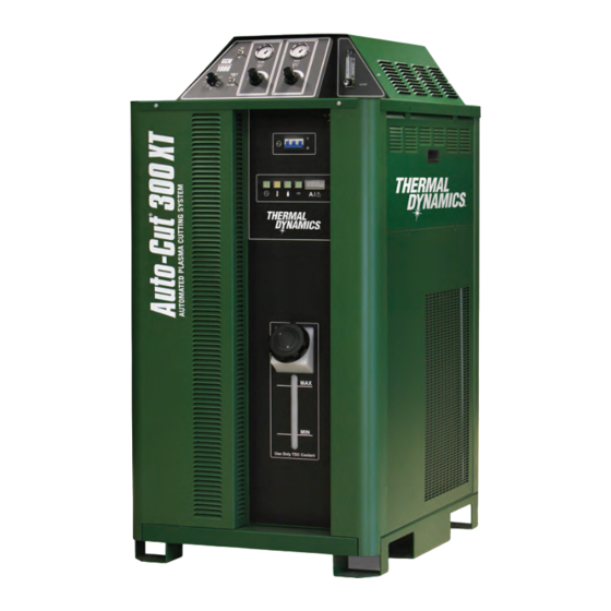
- Page 1 ® 480V AUTO-CUT 300 XT ™ PLASMA CUTTING SYSTEM Operating Manual Revision: AE Issue Date: May 27, 2015 Manual No.: 0-5300 ThermalDynamics.com...
- Page 2 ® WE APPRECIATE YOUR BUSINESS! Congratulations on your new Thermal Dynamics product. We are proud to have you as our customer and will strive to provide you with the best service and reliability in the industry. This product is backed by our extensive warranty and world-wide service network.
- Page 3 Manufacturer assumes no liability for its use. Plasma Cutting Power Supply, Auto-Cut 300 XT™ ® Operating Manual No. 0-5300 Published by: Thermal Dynamics Corporation. 2800 Airport Rd. Denton, Texas 76207 www.thermal-dynamics.com © Copyright 2013, 2014, 2015 by Thermal Dynamics Corporation.
- Page 4 Be sure this information reaches the operator. You can get extra copies through your supplier. CAUTION These INSTRUCTIONS are for experienced operators. If you are not fully familiar with the principles of operation and safe practices for arc welding and cutting equipment, we urge you to read our booklet, “Precautions and Safe Practices for Arc Welding, Cutting, and Gouging,”...
- Page 5 ASSUREZ-VOUS QUE CETTE INFORMATION EST DISTRIBUÉE À L’OPÉRATEUR. VOUS POUVEZ OBTENIR DES COPIES SUPPLÉMENTAIRES CHEZ VOTRE FOURNISSEUR. ATTENTION Les INSTRUCTIONS suivantes sont destinées aux opérateurs qualifiés seulement. Si vous n’avez pas une connaissance approfondie des principes de fonctionnement et des règles de sécurité pour le soudage à l’arc et l’équipement de coupage, nous vous suggérons de lire notre brochure «...
- Page 6 This Page Intentionally Blank...
-
Page 7: Table Of Contents
TABLE OF CONTENTS SECTION 1: SAFETY .......................1-1 1.01 Safety Precautions - ENGLISH ..............1-1 1.02 Précautions de sécurité - FRENCH CANADIAN ........1-6 SECTION 2: SPECIFICATIONS ....................2-1 2.01 General Description Of The System ............2-1 2.02 Plasma Power Supply .................2-1 2.03 Plasma Cutting Torch ..................2-1 2.04 System Component Layout .................2-1 2.05... - Page 8 TABLE OF CONTENTS SECTION 6: REPLACEMENT ASSEMBLIES & PARTS ............6-1 6.01 Replacement Power Supply ................6-1 6.02 Leads and Cables ..................6-1 6.03 Power Supply External Replacement Parts ..........6-3 6.04 Power Supply Replacement Parts - Lower Right Side ........6-4 6.05 Power Supply Replacement Parts - Upper Right Side ........6-5 6.06 Power Supply Replacement Parts - Left Side ..........6-6 6.07...
-
Page 9: Section 1: Safety
AUTO-CUT 300 XT SECTION 1: SAFETY 1.01 Safety Precautions - ENGLISH WARNING: These Safety Precautions are for your protection. They summarize precautionary information from the references listed in Additional Safety Information section. Before performing any installation or operating procedures, be sure to read and follow the safety precautions listed below as well as all other manuals, material safety data sheets, labels, etc. - Page 10 AUTO-CUT 300 XT ELECTRICAL SHOCK -- Contact with live electrical parts and ground can cause severe injury or death. DO NOT use AC welding current in damp areas, if movement is confined, or if there is danger of falling. 1. Be sure the power source frame (chassis) is connected to the ground system of the input power.
- Page 11 AUTO-CUT 300 XT CYLINDER HANDLING -- Cylinders, if mishandled, can rupture and violently release gas. Sudden rupture of cylinder, valve, or relief device can injure or kill. Therefore: 1. Use the proper gas for the process and use the proper pressure reducing regulator designed to operate from the compressed gas cylinder.
- Page 12 AUTO-CUT 300 XT Meaning of symbols - As used throughout this manual: Means Attention! Be Alert! Your safety is involved. Means immediate hazards which, if not avoided, will result in immediate, serious per- DANGER sonal injury or loss of life.
- Page 13 AUTO-CUT 300 XT This Page Intentionally Blank Manual 0-5300 SAFETY INSTRUCTIONS...
-
Page 14: Précautions De Sécurité - French Canadian
AUTO-CUT 300 XT 1.02 Précautions de sécurité - FRENCH CANADIAN AVERTISSEMENT : Ces règles de sécurité ont pour but d’assurer votre protection. Ils récapitulent les informations de précaution provenant des références dans la section des Informations de sécurité sup- plémentaires. Avant de procéder à l’installation ou d’utiliser l’unité, assurez-vous de lire et de suivre les précautions de sécurité... - Page 15 AUTO-CUT 300 XT 5. Assurez-vous de ne pas excéder la capacité de l’équipement. Par exemple, un câble de soudage surchargé peut surchauffer et provoquer un incendie. 6. Une fois les opérations terminées, inspectez l’aire de travail pour assurer qu’aucune étincelle ou projec- tion de métal incandescent ne risque de provoquer un incendie ultérieurement.
- Page 16 AUTO-CUT 300 XT LES VAPEURS ET LES GAZ -- peuvent causer un malaise ou des dommages corporels, plus particu- lièrement dans les espaces restreints. Ne respirez pas les vapeurs et les gaz. Le gaz de protection risque de causer l’asphyxie.
- Page 17 AUTO-CUT 300 XT 4. N’utilisez pas l’équipement de façon abusive. Gardez l’équipement à l’écart de toute source de chaleur, notamment des fours, de l’humidité, des flaques d’eau, de l’huile ou de la graisse, des atmosphères corrosives et des intempéries. 5. Laissez en place tous les dispositifs de sécurité et tous les panneaux de la console et maintenez-les en bon état.
- Page 18 AUTO-CUT 300 XT MISE EN GARDE L’équipement pourrait basculer s’il est placé sur une surface dont la pente dépasse 15°. Vous pourriez vous blesser ou endommager l’équipement de façon importante. 15° Art# A-12726 MISE EN GARDE Soulevez à l’aide de la méthode et des points d’attache illustrés afin d’éviter de vous blesser ou d’endommager...
-
Page 19: Section 2: Specifications
AUTO-CUT 300 XT SECTION 2: SPECIFICATIONS 2.01 General Description Of The System A typical Auto-Cut 300 XT™ plasma cutting system includes: • One Power Supply • General Purpose Plasma Cutting Torch with Connecting Leads • Torch Spare Parts Kit The components are connected at installation. -
Page 20: Power Supply Specifications & Electrical Requirements
AUTO-CUT 300 XT 2.05 Power Supply Specifications & Electrical Requirements Auto-Cut 300 XT™ Specifications & Design Features Max OCV (U0) 425 vdc Minimum Output Current 5 Amps Max Output Current 300 Amps Output Voltage 60 - 180 vdc 300 Amp System... -
Page 21: Power Supply Dimensions
AUTO-CUT 300 XT 2.06 Power Supply Dimensions 55 inch 1397 mm 40.6 inch 1031.2 mm 610 lb / 277 kg 27.5 inch 698.5 mm Art # A-11918 Manual 0-5300 SPECIFICATIONS... -
Page 22: Power Supply Rear Panel Features
AUTO-CUT 300 XT 2.07 Power Supply Rear Panel Features J56 Gas Control J58 Arc Starter Gas Selection Switch Plasma Gas - In System Earth Water - In Ground Shield Gas - In Customer C.C.M. Optional Port J55 To Gas Control... -
Page 23: Gas Requirements
The customer will provide all gases and pressure regulators. Gases must be of high quality. Pressure regulators shall be equipped with stainless-steel diaphragms and installed as close as possible to the Gas Console. Auto-Cut 300 XT™ Power Supply: Gas Pressures, Flows, and Quality Requirements Quality... - Page 24 AUTO-CUT 300 XT 2.10 XT -301 Torch Specifications A. Torch Dimensions Art # A-11538 End Cap 19" 2.25" 482.7 mm 57.15 mm Mounting Tube 2.0" 15.5" 50.8 mm 393.8 mm 6.3" 160.1 mm 2.4" 61 mm 3.98" 101.1 mm 2.7"...
- Page 25 AUTO-CUT 300 XT C. Torch Parts (Generic Parts Shown) Cartridge Shield Retainer Assemble First Art # A-11915 D. Parts - In - Place (PIP) The torch is designed for use with a power supply which senses coolant return flow to confirm that torch parts are in place.
-
Page 26: Xt Tm -301 Torch Specifications
AUTO-CUT 300 XT E. Type Cooling Combination of gas stream through torch and liquid cooling. F. XT -301 Torch Data (with Auto-Cut 300 XT™ Power Supply) -301 Torch Ratings (when used with Auto-Cut 300 XT™Power Supply) Ambient 104° F Temperature 40°... -
Page 27: Section 3: Installation
Cooling System Requirements Coolant must be added to the system on installation. The amount required varies with torch leads length. Victor Thermal Dynamics recommends the use of its coolants 7-3580 and 7-3581 (for low temperatures). Coolant Capabilities Cat. Number and Mixture... -
Page 28: Cables And Leads Identification
AUTO-CUT 300 XT 3.02 Cables and Leads Identification Refer to section 3.05 and 3.06 for ground connections and ground cables. Arc Starter / Gas Control Module G: Torch Lead Set, Shielded (GCM-1000XT) - Coolant Supply Pilot Return w/ Negative Control... -
Page 29: Cables & Leads Identification
AUTO-CUT 300 XT 3.03 Cables & Leads Identification #8 AWG Cable Pilot Return, Power Supply to Arc Starter 2/0 (70 mm ) Cable Negative Lead, Power Supply to Arc Starter Green Green Coolant Leads, Power Supply to Arc Starter Control Cable, Power Supply... -
Page 30: Position The Power Supply
AUTO-CUT 300 XT 3.04 Position the Power Supply WARNING Do not touch live electrical parts. Disconnect input power conductors from de-energized supply line before moving unit. FALLING EQUIPMENT can cause serious personal injury and equipment damage. Use the lifting eye when using straps to lift the power supply. -
Page 31: Connect Input Power And Ground Cables
AUTO-CUT 300 XT 3.05 Connect Input Power and Ground Cables Connect Input Power and System Ground Cables 1. Remove the input power cover to the right of the coolant filter at the rear of the power supply. To do this remove the two screws then lift up and pull away. -
Page 32: Connect Work Cable To Power Supply
AUTO-CUT 300 XT 3.06 Connect Work Cable to Power Supply 1. Remove the output power cover to the left of the coolant filter at the rear of the power supply. To do this remove the two screws then lift up and pull away. -
Page 33: Ground Connections
For Victor Thermal Dynamics components it is recommended to use a minimum of 10 AWG (European 6 mm wire or flat copper braid with cross section equal to or greater than 10 AWG connected to the cutting table frame. - Page 34 AUTO-CUT 300 XT C. Creating An Earth Ground 1. To create a solid, low resistance, earth ground, drive a 1/2 in (12 mm) or greater diameter copper clad ground rod at least 6 - 8 ft (1.8 - 2.4 m) into the earth so that the rod contacts moist soil over most of its length. Depend- ing on location, a greater depth may be required to obtain a low resistance ground (see NOTE).
- Page 35 AUTO-CUT 300 XT R = 1.2K, 15W (2.2K, 25W for 220 VAC) Ground Rod with other connections removed Triad N-68X Triad N-68X 0.1 VAC = 1 OHM, 0.3 VAC = 3 OHM, etc. 220 VAC 120 VAC Utility (building) GND...
-
Page 36: Connect Gas And Coolant Supply Lines
AUTO-CUT 300 XT 3.09 Connect Gas and Coolant Supply Lines 1. Connect the gas supply lines to the appropriate input ports as shown, upper left. NOTE! Coolant lines are factory installed. If attaching optional HE400 see subsection 3.14 Plasma Gas - In... -
Page 37: Cables For Cnc, Arc Starter/Gas Control
AUTO-CUT 300 XT 3.10 Cables for CNC, Arc Starter/Gas Control 1. Connect one end of each cable to the power supply. Some cables shown are options and may not apply to your system. 2. Connect the other end of the CNC cable to the CNC device. -
Page 38: Set Switches On The Command - Control Module
AUTO-CUT 300 XT 3.11 Set Switches on the Command - Control Module Remove the power supply upper right side. Set switches on the CCM (Command-Control Module) per the illustra- tions. Switch settings and connection details are provided in the Appendix. Any changes made require a restart of the power supply. - Page 39 AUTO-CUT 300 XT CAUTION Printed circuit boards in the Command - Control Module are static - sensitive. Discharge any built-up static charges in your body or surroundings before touching the printed circuit boards. SW11 SW12 SW13 SW-6: OK-to-Move: Contact closure, 120VAC @ 1A (Factory default setting) or DC Volts (16-18vdc@ up to 100 ma.)
-
Page 40: Height Control Connections
AUTO-CUT 300 XT 3.12 Height Control Connections The terminal strip provides connections to negative Arc Volts (Torch or electrode), Tip Volts (Pilot) and Work. These are for a height control that requires connection to the full non-divided arc voltage. Also available on the terminal strip are 120VAC and 24 VAC. -
Page 41: Connect Torch Leads To The Gas Control Module / Arc Starter
AUTO-CUT 300 XT 3.13 Connect Torch Leads to the Gas Control Module / Arc Starter 1. Remove the top cover from the Gas Control Module / Arc Starter. 2. Pass the torch leads and coolant leads through the torch leads port on the back of the module. Ensure that the leads outer jacket slides into the port. - Page 42 AUTO-CUT 300 XT Coolant Return Coolant Supply Connection (Tagged Red) Connection (Tagged Green) Plasma Gas Connection Shield Gas Connection Torch Leads Art # A-04832 5. Fold the end of the leads outer jacket back over the connection ring inside the module. Slide the leads clamp over the jacket and fasten the clamp and jacket to the connection ring.
-
Page 43: Torch Head Installation And Connection
AUTO-CUT 300 XT 3.14 Torch Head Installation and Connection Install the Torch as follows: 1. Install the torch mounting block on the cutting table (gantry). Fasten the block in place. 2. Leave the end cap in place on the torch leads. Remove and discard the protective end caps from the Mount- ing Tube. -
Page 44: Install Consumable Torch Parts
AUTO-CUT 300 XT 5. Slide the positioning tube down to the torch head. Hold the torch head stationary. Rotate the positioning tube onto the torch head. Pull the leads back as needed to ensure a proper fit through the Mounting Tube. - Page 45 AUTO-CUT 300 XT 4. Insert the stack of consumable parts into the cartridge. Ensure that the large O-ring on the torch tip fits completely into the cartridge. If any part of the O-ring protrudes from the cartridge, the parts are not seated properly.
- Page 46 AUTO-CUT 300 XT 5. Use the removal tool to hold the cartridge assembly, while turning the shield cap onto the cartridge assem- bly. When this group is fully assembled, the shield should protrude from the front of the shield cup 0.063”...
- Page 47 AUTO-CUT 300 XT 7. Confirm proper parts assembly as shown. Torch Head Torch Head O-Ring 0.063 - 0.083" (1.6 - 2.1 mm) Protrusion Art # A-07202 8. Slide the ohmic clip over the shield cup if using ohmic torch height sensing.
-
Page 48: Voltage Divider For Ihc Torch Height Control
AUTO-CUT 300 XT 3.16 Voltage Divider for iHC Torch Height Control For best plasma cutting performance it is necessary to maintain a constant height (standoff) above the metal while cutting. Cutting tables use a Torch Height Control (THC), also called a Z axis control, most of which use feedback from the arc voltage to control the height. - Page 49 AUTO-CUT 300 XT Control Cable. The iHC board can be supplied with a wire harness and connector (shown in previous image), to be installed in the rear panel hole labeled “Height Control” . The connector mates with a cable from the iHC. For other height control V-D boards a strain relief can be installed in this hole for those cables.
-
Page 50: 3:17 Fill Cooling System
AUTO-CUT 300 XT 3:17 Fill Cooling System 1. Fill the coolant tank to the level shown, with Thermal Dynamics coolant. The coolant level is visible through the translucent coolant tank. The amount of coolant required varies with torch leads length. - Page 51 2. After the complete system has been installed, check that the coolant has been pumped through the system as follows (see NOTE): NOTE! The system will most likely require more coolant after turning the system ON for the first time. a.
- Page 52 This Page Intentionally Blank...
-
Page 53: Section 4: Operation
AUTO-CUT 300 XT SECTION 4: OPERATION 4.01 Power Supply Indicators AC Indicator Gas Indicator Status Indicator Temp Indicator DC Indicator Art # A-11909 AC Power Lamp Indicates unit has passed the input power tests and AC power is being supplied to the inverter modules via the input contactor when the ON/OFF switch is in ON position. -
Page 54: Control Console Features
AUTO-CUT 300 XT 4.02 Control Console Features Art # A-11917 Shield Gas Plasma Gas Pressure Gauge Pressure Gauge Run / Set Selector Amperage PLASMA SHIELD Selector SHIELD GAS H 2 0 MIST H 2 0 MIST GCM 1000 XT GAS CONTROL MANAGEMENT SYSTEM... -
Page 55: System Operation
AUTO-CUT 300 XT 4.03 System Operation This section contains operating information which is specific to the power supply. WARNING Frequently review the safety precautions in Section 1. If the power supply cord has a plug or is not permanently connected to power, be sure the power to the outlet is disconnected when inserting the plug into the outlet. - Page 56 AUTO-CUT 300 XT 3. Set Gas Pressures a. Place RUN/SET switch in SET mode. b. Adjust plasma and shield pressure regulators to correct pressure or correct flow if using H O Mist option. (refer to cut chart manual for required pressure/flow.) c.
-
Page 57: Gas Selection
AUTO-CUT 300 XT Operational Suggestions 1. Wait four minutes before setting the ON/OFF switch to OFF after operation. This allows the cooling fans to run to dissipate operating heat from the power supply. 2. For maximum parts life, do not operate the pilot arc any longer than necessary. -
Page 58: Power Supply Status Codes
AUTO-CUT 300 XT 3. Water Shield • Normally used with nitrogen. • Provides very smooth cut surface. • Reduces smoke and heat input to the workpiece. • Effective up to 1/2 inch (12.7 mm) maximum material thickness. • Tap water provides low operating expense. - Page 59 AUTO-CUT 300 XT CCM Status Code Group 2 -- Plasma Power Supply Code Message Remedy / Comments Missing AC Phase Blown fuse, Bad power cable connection; Defective System Bias PCB Not used Reserved for legacy product Not used Reserved for legacy product...
- Page 60 AUTO-CUT 300 XT Code Message Remedy / Comments Inverter 1A Incom- Unsupported Inverter Revision; Ribbon cable CCM J31 to Inverter Module 1 Section A dam- patible Revision aged; CCM code version incompatible with Inverter revision or model Inverter 1B Incom- Unsupported Inverter Revision;...
- Page 61 AUTO-CUT 300 XT Code Message Remedy / Comments Not used Reserved for other model with another inverter section Inverter Input Voltage fault; voltage out of range or missing phase at AC Input of Inverter Inverter 3A Input Module 3 Section A; Poor AC Power Quality; Defective W2 contactor; Loose or open connec- Voltage Error tion between input terminals and W2 contactor or contactor and input of Inverter Section;...
- Page 62 AUTO-CUT 300 XT Code Message Remedy / Comments Inverter 2A No Input Inverter section may have no input power. Contactor W1 not closed; Defective contactor or CB4 Power tripped; Inverter section input not connected; Defective Inverter. Inverter 2B No Input Inverter section may have no input power.
- Page 63 AUTO-CUT 300 XT CCM Status Code Group 4 -- Torch Coolant System Code Message Remedy / Comments Coolant Level low Check coolant level, add as needed. Coolant flow as measured by flow switch FS1 is less than 0.7 gpm (0.25 for Pak200i);...
- Page 64 AUTO-CUT 300 XT CCM Status Code Group 6 -- CCM Code Message Remedy / Comments Analog Voltage Error Defective CCM, replace. ADC or DAC error Defective CCM, replace. Reserved No information available; Contact customer service Data Memory error Defective CCM, replace.
-
Page 65: Cut Quality
AUTO-CUT 300 XT 4.06 Cut Quality Cut quality requirements differ depending on application. For instance, nitride build-up and bevel angle may be major factors when the surface will be welded after cutting. Dross-free cutting is important when finish cut quality is desired to avoid a secondary cleaning operation. - Page 66 AUTO-CUT 300 XT Direction of Cut The plasma gas stream swirls as it leaves the torch to maintain a smooth column of gas. This swirl effect results in one side of a cut being more square than the other. Viewed along the direction of travel, the right side of the cut is more square than the left.
-
Page 67: Section 5: Maintenance
AUTO-CUT 300 XT SECTION 5: MAINTENANCE 5.01 General Maintenance Perform the following checks periodically to ensure proper system performance. Power Supply Maintenance Schedule Daily Check coolant level; add coolant as needed. Check gas hose connections and pressures. Check cooling fan; clean as needed. -
Page 68: Coolant Replacement Procedure
AUTO-CUT 300 XT 5.03 Coolant Replacement Procedure Replace coolant as follows: 1. Disconnect the system from main input power. 2. Remove the lower right side panel. 3. Locate the coupling in the coolant line that comes from the bottom of the coolant tank, #1 in the following illustration. -
Page 69: Arc Starter Service
AUTO-CUT 300 XT 5.04 Arc Starter Service Arc Starter Service Chart Symptom Cause Check Remedy Flush system, Coolant has become conductive Use conductivity meter replace coolant. Pilot return wire not connected Visual inspection Connect Wire. Spark gap set too close Check with feeler gauge Set to 0.063”... -
Page 70: Arc Starter Spark Gap Adjustment
AUTO-CUT 300 XT 5.05 Arc Starter Spark Gap Adjustment 1. Shut off input power. Remove the top console cover. 2. Adjust the spark gap as shown. Re-install the top cover. 0.063" ± 0.002" 1.6 ± 0.05 mm Art # A-11913 5-�... -
Page 71: Section 6: Replacement Assemblies & Parts
Control Cable Positioning Primary power Tube Torch CNC Cable Work Cable Work Art # A-11902_AB Leads Catalog Numbers; Auto-Cut 300 XT Power Supply, XT-301 Torch Leads Length 125 ft 3 ft 5 ft 10 ft 15 ft 25 ft 35 ft... - Page 72 AUTO-CUT 300 XT NOTE! Supply lead set includes Pilot Return Cable, Negative Cable, Coolant Supply & Return Hoses, and Control Cable. #8 AWG Cable Pilot Return, Power Supply to Arc Starter 2/0 (70 mm ) Cable Negative Lead, Power Supply...
-
Page 73: Power Supply External Replacement Parts
AUTO-CUT 300 XT 6.03 Power Supply External Replacement Parts Item # Description Catalog # GCM 1000 XT Top Cover 9-7345 Power and Leads Cable Covers 9-7346 Lifting Eye, Cable 9-7347 Upper Side Covers (2 total) 9-7301 Lower Left Side Cover... -
Page 74: Power Supply Replacement Parts - Lower Right Side
AUTO-CUT 300 XT 6.04 Power Supply Replacement Parts - Lower Right Side Item # Description Catalog # Coolant Tank, Cap 9-7305 Coolant Tank 9-7306 Sensor, Coolant level 9-7307 Pump, Coolant, Assembly (with motor) 9-7309 Pump, Coolant, Assembly (no motor) 9-7422... -
Page 75: Power Supply Replacement Parts - Upper Right Side
AUTO-CUT 300 XT 6.05 Power Supply Replacement Parts - Upper Right Side Item # Description Ref. Des. Catalog # Relays, Pump / Fan MC3 / MC2 9-7314 Relay, Inrush Control 9-7336 Relay, Inrush 9-7337 Resistor, Inrush 9-7376 Auxilliary Transformer 9-7315... -
Page 76: Power Supply Replacement Parts - Left Side
AUTO-CUT 300 XT 6.06 Power Supply Replacement Parts - Left Side Item # Description Ref. Des. Catalog # Suppressor PCB 9-9254 Main Contactor (2 total) W1, W2 9-7318 Inverter Module, Full (2 total) 480 VAC 9-7330 Inverter Module, Partial 480 VAC... -
Page 77: Power Supply Replacement Parts Ras - Gcm 1000 Xt
AUTO-CUT 300 XT 6.07 Power Supply Replacement Parts RAS - GCM 1000 XT Item # Description Ref. Des. Catalog # Gas Solenoid (3 required per unit) 9-6319 Water Filter Assembly 8-3460 HF Transformer 9-4959 Pressure Switch 9-6318 PCB, RAS1000 RF Cap Board... -
Page 78: Power Supply Replacement Parts - Rear Panel
AUTO-CUT 300 XT 6.08 Power Supply Replacement Parts - Rear Panel Item # Description Breaker Rating Cicuit Rating Ref. Des. Catalog # Coolant Filter Assy. 9-7320 Coolant Filter 9-7322 Gas Selection Switch 9-3325 Fuse, 8A SB 500V (2 total) 9-7377... -
Page 79: Power Supply Replacement Parts - Front Of Gcm1000 Xt
AUTO-CUT 300 XT 6.09 Power Supply Replacement Parts - Front of GCM1000 XT Item # Description Catalog # Pressure Gauge 8-6800 Gas Regulator 9-9509 Run/Set Selector Switch 9-3426 Potentiometer with Knob 9-2685 Shield Gas Selector Switch 9-3427 Flowmeter, H 9-7762... -
Page 80: Recommended Gas Supply Hose
AUTO-CUT 300 XT 6.10 Recommended Gas Supply Hose Item # Description Catalog 3/8”Gray Synflex Hose. No fittings included. Catalog number per foot 9-3616 �-10 REPLACEMENT PARTS Manual 0-5300... -
Page 81: Section 7: Torch Maintenance
AUTO-CUT 300 XT SECTION 7: TORCH MAINTENANCE 7.01 Consumable Removal 1. Use the removal tool to hold the Shield Cup & Cartridge Assembly stationary. Turn the Shield Cup to remove it from the Cartridge Assembly Cartridge Tool Assembled Cartridge Art # A-04344_AB Shield Cup 2. -
Page 82: O-Ring Lubrication
Art # A-04066_AC Art # A-04071_AC CAUTION Use only Thermal Dynamics No. 9-4893 O-Ring Lubricant (Christo Lube MCG-129) with this torch part. Use of other lubricants may cause irreparable damage to the torch. 7.03 Parts Wear Replace the Gas Distributor if it is charred or cracked. -
Page 83: Torch Consumables Installation
AUTO-CUT 300 XT 7.04 Torch Consumables Installation 1. Install the consumables as follows: WARNINGS Do not install consumables into the Cartridge while the Cartridge is attached to the Torch Head. Keep foreign materials out of the consumables and Cartridge. Handle all parts carefully to avoid damage, which may affect torch performance. - Page 84 AUTO-CUT 300 XT 1: Stack Parts 2: Press Cartridge onto Stacked Parts Electrode Plasma Gas Distributor O-Ring on Tip No Gaps Between Parts Shield Gas Cartridge Covers Distributor O-Ring on Torch Tip Shield Cap 4: Check Shield Cap Protrusion 3: Thread Shield Cup onto Cartridge...
- Page 85 AUTO-CUT 300 XT 2. Remove the Removal Tool from the Cartridge and install the assembled Cartridge onto the Torch Head. CAUTION The cartridge assembly must cover the O-Ring on the torch head. Do not force the cartridge if it will not tighten fully. Remove the cartridge assembly and gently clean the threads on the torch head with a wire brush.
- Page 86 AUTO-CUT 300 XT E. Coolant Leak Trouble-Shooting Never operate the system if coolant leaks from torch. A steady drip indicates that torch parts are damaged or in- stalled improperly. Operating the system in this condition can damage the torch head. Refer to the following chart for guidance on coolant leakage from the torch head.
-
Page 87: Appendix 1: Cnc Control Module
AUTO-CUT 300 XT APPENDIX 1: CNC Control Module Control PCB Connections (LV) OK To Move 2 High +10V Analog Current Control Wiper / Input Low (-) Divided Arc Volts Output Start/Stop Input Stop (NC) (LV) OK To Move 2 CNC Plasma Enable... -
Page 88: Cnc Functions
AUTO-CUT 300 XT CNC functions CNC I/O circuits provide at least 1000V galvanic isolation from the plasma power supply. While the CNC circuits are isolated from the power supply, many of the signal returns on J15 and TB1, TB2 & TB3 are common to each other. - Page 89 AUTO-CUT 300 XT Internal CNC connections. TB1, TB2 & TB3 on CCM module. Connections are provided on the CCM module TB1, TB2 & TB3 terminal blocks including most of the rear panel functions plus some additional features. All these signals are isolated from the plasma power supply but signals marked (comm.) and (-) are common to each other.
- Page 90 AUTO-CUT 300 XT CNC Input / Output Descriptions All inputs except the Analog Current Control are digital active low (contact or SW closure). CNC Enable / Disable ( input) — Requires closed connection rated for 10 ma. @ 20VDC for unit to operate.
- Page 91 AUTO-CUT 300 XT OK to Move2 – Provides a second set of N.O. contacts that close when arc transfer is detected. Contacts are rated for maximum of 24 VAC/DC @ 1A. Simplified CNC Circuit. +10V @ 10ma. For Remote CC Pot – Previously CCM versions if one wanted to use a potentiometer for the Remote Analog Current Control (CC) input an external 10 V supply was required for Pot High..
- Page 92 AUTO-CUT 300 XT Simplified CNC Circuit Autocut 300 XT Simplified CNC OK TO MOV E SELECT 18 V D C or Con tacts SW6A D C VO LT S +18VDC OK2 (cont act) C ONTA CT S +10V (CC Pot Hi )
- Page 93 AUTO-CUT 300 XT J54 - Rem ote HM I & CN C CO M M (100) 1 - 24 V AC (101) 2 - 24 V AC Re t (102) 3- Jumper to 24 V AC Harness to Relay PCB...
- Page 94 AUTO-CUT 300 XT CNC Connections Cutting Machine CNC Cable Power Supply START/STOP ..Source, 16 VDC, 10 ma..Divided Arc V (-) ..Divided Arc V (+) ..Pre Flow ON (+) ..Pre Flow ON (-) ..Corner Current Reduction (+)
-
Page 95: Cnc Cable Color Code
AUTO-CUT 300 XT CNC Cable Color Code TABLE 1: CABLE ITEM#4 COLOR CODE TABLE COLOR SIGNAL DESCRIPTION LOCATION WHITE/BLUE START CNC (+) WHITE/VIOLET START CNC (-) WHITE/BROWN/VIOLET DIV ARC (-) WHITE/BROWN DIV ARC(+) YELLOW PREFLOW ON (+) GREEN COMM 1K... -
Page 96: Appendix 2: Ccm Cpu Pcb Layout
AUTO-CUT 300 XT APPENDIX 2: CCM CPU PCB Layout = Test Point Art # A-11675_AB A-10 APPENDIX Manual 0-5300... - Page 97 AUTO-CUT 300 XT CCM CPU PCB Test Points ISO +5.0V +24V +3.3V ISO GND +5.0V TOTAL DEMAND 3.3V=400A TP10 TP11 CPU TEMP SENSE TP12 +3.3VA TP13 -15VDAC TP1� TP15 +15VDAC TP16 CLKO TP18 OSC_CLOCK LED Reference Fiber Out 2 Fiber Out 1...
-
Page 98: Appendix 3: Ccm I/O Pcb Layout
AUTO-CUT 300 XT APPENDIX 3: CCM I/O PCB Layout = Test Point A-12 APPENDIX Manual 0-5300... - Page 99 AUTO-CUT 300 XT CCM I/O PCB J Connectors BASIC CNC Test Points EXTENDED CNC RELAY - INTERFACE BOARD /COOLANT FANS ON /TORCH PUMP ON ARC / TIP VOLTS LOW COOLANT FLOW (SW) TEST GAS BOX COOLANT FLOW SIGNAL (PULSE) +15V ISOLATED...
-
Page 100: Appendix 4: Pilot Pcb Layout
AUTO-CUT 300 XT APPENDIX 4: Pilot PCB Layout = Test Point Art # A-11677 A-1� APPENDIX Manual 0-5300... - Page 101 AUTO-CUT 300 XT Pilot PCB Test Points PILOT GATE TP� LED Reference Green PILOT ENABLE Green +5V Manual 0-5300 APPENDIX A-15...
-
Page 102: Appendix 5: Relay And Interface Pcb Layout
AUTO-CUT 300 XT APPENDIX 5: Relay and Interface PCB Layout = Test Point Art # A-11678_AB A-1� APPENDIX Manual 0-5300... - Page 103 AUTO-CUT 300 XT Relay and Interface PCB Test Points -15V +5VDC +12V +24V +15V +5VDC LED Reference Green 1 TORCH GAS ON Green PILOT ENABLE Green PILOT CURRENT DETECTED Green WORK CURRENT DETECTED Green CONTACTORS ON Green RF ON Green FANS ON...
-
Page 104: Appendix 6: Display Pcb Layout
AUTO-CUT 300 XT APPENDIX 6: Display PCB Layout = Test Point Art # A-11679 A-1� APPENDIX Manual 0-5300... - Page 105 AUTO-CUT 300 XT Display PCB Test Points +5VDC +24VDC Manual 0-5300 APPENDIX A-19...
-
Page 106: Appendix 7: System Bias Pcb Layout
AUTO-CUT 300 XT APPENDIX 7: System Bias PCB Layout = Test Point Art # A-11680 A-20 APPENDIX Manual 0-5300... - Page 107 AUTO-CUT 300 XT System Bias PCB Test Points 24VDC DC INPUT POSITIVE TP� Vcc1 Vcc2 GATE PRIMARY GND +12V PRIMARY P_ISOL_GND TP10 DC SENSE POSITIVE LED Reference MISSING PHASE AC V HIGH AC V LOW Green VAC_IDA Green +12V PRIMARY...
-
Page 108: Appendix 8: Main Inverter Bottom Pcb Layout
AUTO-CUT 300 XT APPENDIX 8: Main Inverter Bottom PCB Layout = Test Point A-22 APPENDIX Manual 0-5300... - Page 109 AUTO-CUT 300 XT Main Inverter Bottom PCB Test Points GATE 2A GATE 1A GATE 3A GATE 4A GATE 2B GATE 1B GATE 4B GATE 3B TP10 +12VP TP11 +12VDC TP12 THERMISTOR SIDE A TP13 THERMISTOR SIDE B TP14 +5VDC TP15...
-
Page 110: Appendix 9: Main Inverter Top Pcb Layout
AUTO-CUT 300 XT APPENDIX 9: Main Inverter Top PCB Layout = Test Point A-2� APPENDIX Manual 0-5300... - Page 111 AUTO-CUT 300 XT Main Inverter Top PCB Test Points GATE 2A GATE 1A GATE 3A GATE 4A GATE 2B GATE 1B GATE 4B GATE 3B TP10 +12VP TP11 +12VDC TP12 THERMISTOR SIDE A TP13 THERMISTOR SIDE B TP14 +5VDC TP15...
-
Page 112: Appendix 10: Control And Fault Pcb Layout
AUTO-CUT 300 XT APPENDIX 10: Control and Fault PCB Layout = Test Point Art # A11683_AB A-2� APPENDIX Manual 0-5300... - Page 113 AUTO-CUT 300 XT Control and Fault PCB Test Points TP22 +12VDC TP23 +5VDC TP24 GATE 1+ TP25 A_OUT1 TP2� B_OUT1 TP27 GATE 1- TP2� I_SNS1 TP29 GATE 2+ TP30 I_DMD1 0.5V-6.7V TP31 GATE 2- TP32 -12VDC TP33 START 2 TP34...
-
Page 114: Appendix 11: Cap Bias Bottom Pcb Layout
AUTO-CUT 300 XT APPENDIX 11: Cap Bias Bottom PCB Layout Art # A-11685_AB A-2� APPENDIX Manual 0-5300... -
Page 115: Appendix 12: Cap Bias Top Pcb Layout
AUTO-CUT 300 XT APPENDIX 12: Cap Bias Top PCB Layout Art # A-11686_AB Manual 0-5300 APPENDIX A-29... -
Page 116: Appendix 13: Suppressor Pcb Layout
AUTO-CUT 300 XT APPENDIX 13: Suppressor PCB Layout Art # A-11684_AB A-30 APPENDIX Manual 0-5300... -
Page 117: Appendix 14: Cooling Diagram
AUTO-CUT 300 XT APPENDIX 14: COOLING DIAGRAM Manual 0-5300 APPENDIX A-31... -
Page 118: Appendix 15: System Schematic
AUTO-CUT 300 XT APPENDIX 15: System Schematic pg 1 INVERTER MODULE (IM) #3 (top) IM #3 Section B (upper) AC INPUT J105B J100 -- 30 CKT RIBBON J104B J103B 019X502700 J105A AC INPUT IM #3 Section A (lower) J100 -- 30 CKT RIBBON... - Page 119 AUTO-CUT 300 XT TO CCM CPU PCB J36 (Sht 2, C3) TORCH (49F) (49) ELECTRODE (-) (51F) PILOT BOARD TEST POINTS WORK (+) LED'S TP1 GND (49) TP2 PILOT GATE D2 PILOT ENABLE TP3 +5V J102B D11 +5V OUTPUT TO CCM...
-
Page 120: Appendix 16: System Schematic Pg2
AUTO-CUT 300 XT APPENDIX 16: System Schematic pg2 AMBIENT J12 = Mini-Fit Jr COOLANT 400 VAC -- Single 18 AWG in pins 1 & 4 (90) 480 VAC -- Single 18 AWG in pins 1 & 8 230 VAC -- 18 AWG wires in pins 1,5,2,6... - Page 121 AUTO-CUT 300 XT TO PILOT PCB J70 - HE (70) 230 VAC to HE 400 (70) Fan Control 230 VAC _ SW (D2) 230 VAC Ret 230 VAC _ SW _ RET (D2) (96) ARC_SUPPRESSOR Pump Motor Control J59 - RAS...
-
Page 122: Appendix 17: Advanced Troubleshooting
AUTO-CUT 300 XT APPENDIX 17: Advanced Troubleshooting System Overview The Auto-Cut 200 & 300 XT & Ultra-Cut 100, 200, 300 & 400 XT power supplies include one, two or three inverter mod- ules (IM). Each IM may have either 1 or 2 inverter sections designated A or B sections. - Page 123 AUTO-CUT 300 XT will only have ribbon cables in J31 & J32; a 200A will have J31-J33 filled with the others empty. 300A will have J34 missing with the others filled. Other boards in the system include the System Bias Supply, the Relay & Interface PCB, Display PCB, Pilot PCB and AC Suppression PCB.
- Page 124 AUTO-CUT 300 XT The AC Suppression PCB has capacitors and other transient suppression components to protect the system from transients on the AC lines. It also provides power for the neon AC present indicators which illuminate when AC power is connected even with ON-OFF switch, CB1, off.
- Page 125 AUTO-CUT 300 XT Status codes. The codes for the power supply are displayed on the Display PCB 4 digit numerical display. Some codes refer to the Gas Controls but more detailed Gas Control codes will be found on the individual gas controls. The gas con- trols used with the XT family of plasma supplies have not changed.
- Page 126 AUTO-CUT 300 XT Power Supply Status Codes Group 1, Process Codes Plasma Enable Is Disabled Code 101 is activated by either an open circuit between TB1-1 & 2 on CCM I/O PCB or Plasma Enable switched off on the GCM 2010 or on the TSC 3000. TB1-1 & 2 comes from the factory with a jumper installed. An in- staller may remove the jumper and connect a separate Plasma Enable switch or use the Plasma Enable wires included in the 37 pin CNC cable used with the Ultra-Cut XT &...
- Page 127 AUTO-CUT 300 XT If a TSC 3000 is not connected or unit is an Auto-Cut, K7 on the Relay PCB is de-energized and GND is con- nected through its normally closed contacts. If the TSC is connected, 24 VAC through a jumper in the TSC 3000 energizes K7, opening its NC contacts and now GND connects through the TDC 3000 Plasma Enable switch.
- Page 128 AUTO-CUT 300 XT Pilot Ignition Failure Code 102 is activated when there is no pilot current after 15 seconds of firing the Arc Starter. Pilot ignition requires the Pilot board to be enabled, pilot switch (IGBT) turned on and high voltage pulses (HF) from the arc Starter (either the Remote Arc Starter RAS 1000 XT or GCM 1000 XT or the arc starter built in to the AC 200 XT) applied between the tip and the electrode of the torch.
- Page 129 AUTO-CUT 300 XT Arc starter without Spark Gap (Ultra-Cut) 1. Check for power to the RAS 1000XT’s Ignition Module during the 15 seconds following preflow (ignition phase). Arc starter power comes through the rear panel circuit breaker CB4, make sure it isn’t tripped.
- Page 130 AUTO-CUT 300 XT Reasons why RAS Control relay would not close: 6. Pilot current flowing. There actually is pilot current flowing somewhere. Unlikely as it would normally set the 208 fault but we have to rule it out. a. Disconnect J41 on the Pilot board, if HF still doesn’t fire and the Relay board Pilot LED, D11, is still on, it’s due to a fault in the detection circuits.
- Page 131 AUTO-CUT 300 XT Troubleshooting Pilot Board problems. 1. The Pilot board is behind the CCM in the AC 300 XT and all Ultra-Cut XTs or on the upper section of the second inverter module in an AC 200 XT and has two LEDs. The first one, D11, a green LED, indicates the board has bias power and should be on all the time when the unit is turned on.
- Page 132 AUTO-CUT 300 XT Transfer Lost Arc transferred to metal for at least 50 ms. then went out. Causes for 104 code: • Cut demand set much lower than recommended for torch parts, i.e. 100A consumables in torch but cut current set for 30 or 50A (or zero). Current may be too low to keep arc on.
- Page 133 AUTO-CUT 300 XT Visible Pilot: • First the obvious, make sure the work lead is connected both to the work and the power supply. Also make sure the work itself is making good electrical contact with cutting table. If rusty or painted metal, you may need to clean a spot and attach the work lead directly to the metal.
- Page 134 AUTO-CUT 300 XT • A broken pilot wire in the torch lead making intermittent contact can allow piloting or sometimes the torch can transfer using only HF (high frequency). This intermittent connection will upset the tip voltage measurement and can result in the 108 code. Symptom is - it may cut for a short time then fault. Check for an open/broken torch lead pilot wire.
- Page 135 AUTO-CUT 300 XT • Inverter over temperature sets the Fault signal and LED but has its own fault signal to the CCM. See OT Flt below. OT FLT (D14, OT FLT, Inverter Control and Fault board) • Inverter over temperature lights LED D14 on the Inverter Control and Fault board and will latch the fault signal and it’s LED but also has its own separate fault so that will be reported as a code in the range of...
- Page 136 AUTO-CUT 300 XT 2. If D3, Missing Phase LED, is not on check for voltage at J27-3 & 4 on the CCM. Normal voltage, with no missing phase, at J27 (or J62 on the System Bias board) pin 3 and pin 4, relative to I/O PCB ground. (TP1) should be between 10-14VDC with pin 3 being a couple volts higher than pin 4.
- Page 137 AUTO-CUT 300 XT Defective Sensor • The work current sensor, HCT1, receives power, +15VDC and -15VDC from the Relay PCB. Both must be present for the sensor to work properly. Measure between Relay PCB TP1 (or J1-4) to J1-1 for +15VDC and to J1-2 for -15VDC.
- Page 138 AUTO-CUT 300 XT Pilot PCB Pilot current signal is on the 10 pin ribbon cable (Pilot J42, Relay PCB J3) between pins 8 (-) and 9 (+). With no current, the signal should be zero +/- 0.05 V. Also the Relay board has an LED, D11, “Pilot Current Detected”, which will light if the pilot current signal exceeds 0.15V.
- Page 139 AUTO-CUT 300 XT Possible causes for work current signal too high: • HCT1 Work Current Sensor • Relay PCB • CCM Possible cause for work current to low. • All the above plus a short to chassis caused by: o User installed equipment connect behind the current sensor that makes a connection to work or earth allowing current flow to bypass work sensor.
- Page 140 AUTO-CUT 300 XT 4. If it’s the first inverter section or it’s a 100A unit so there’s no other inverter to swap cables with, replace the inverter. Additional hint: Inverter control PCBs have a green LED, D24, PWM ON, that lights when that section is enabled and has a demand signal.
- Page 141 AUTO-CUT 300 XT Possible causes: • Wrong voltage inverter (very unlikely but easy to check). • System Bias board wrong J61 jumper (unlikely but easy to check) • Defective inverter. • Ribbon Cable • CCM • System Bias board defective.
- Page 142 AUTO-CUT 300 XT Troubleshooting: 1. Check that all cables are connected, latches locked down, at both the inverter and CCM ends. 2. If this fault occurs it’s most likely on a 100A unit which only has one section (1B) in addition to the 1A sec- tion.
- Page 143 AUTO-CUT 300 XT If the fault is E239 that means it is currently active, that is, currently detected as being too high. If it’s L239 that means the voltage too high previously but it is not too high now. Applying START will clear the fault unless it becomes active again.
- Page 144 AUTO-CUT 300 XT Troubleshooting: 1. If the fault is L240, applying START will clear the fault unless it becomes active again. An occasional problem may be due to incoming voltage dips or sags (voltage drops lasting from ½ cycle to as much as a minute).
- Page 145 AUTO-CUT 300 XT 247-252 Inverter Fault Once the input contactors close applying voltage to the inverters several tests are performed. The Inverter Fault signal latches on so even if the cause has gone away you can see that there was a fault as indicated by red LED D1, INV FLT on the inverter Control &...
- Page 146 AUTO-CUT 300 XT 259-264 Inverter Over Temperature due to high Ambient. The CCM measures the ambient temperature where the cooling air enters the louvers on the left side of the front panel. If an inverter goes over temperature and we have determined that the ambient exceeds 40 deg C we will get one or more of the high ambient codes, 252-264.
- Page 147 AUTO-CUT 300 XT Possible causes: • The 3 input phases, J103-105 to that inverter section not connected. • The circuit breaker CB2 providing the 120 VAC to the contactor (and Remote Arc Starter) has tripped. • The contactor powering that section (and others) defective.
- Page 148 AUTO-CUT 300 XT Inverter ID Reading Fault. Refer to section for codes 225-230 for a description of the ID signals. If this code appears it means one of these ID signals has gone false some time after power up. Possible causes: •...
- Page 149 Gas pressure faults only show up when you try to start the torch, not during purging or setting flows . With the Auto-Cut 200 XT and the Auto-Cut 300 XT (GCM 1000 XT), the gas pressure sensor is only on the plasma gas and is in series with Run/Set switch.
- Page 150 AUTO-CUT 300 XT 310-313 DFC 3000 Auto Gas Faults. These different codes displayed on the power simply indicate one of the Auto Gas modules (DPC for codes 310 or 311; DMC for 312 and 313 could be either) is reporting a fault. You need to refer to the specific modules blinking red LED status indicator and the Status code tables for more information.
- Page 151 AUTO-CUT 300 XT Troubleshooting: 1. Confirm visually that the level switch float is below the coolant, if not add more coolant to the tank. 2. Check J7 on the Relay board. a. If properly connected remove J7 and check continuity between pins 2 and 4 (pins 2 & 3 of J71 on the switch itself).
- Page 152 AUTO-CUT 300 XT Coolant overheated. TS1 is a linear negative temperature coefficient (NTC) resistor sensor attached to the brass fitting at the exit of the bypass valve. Here we determine the coolant being supplied to the torch is below the required temperature which is currently 75 deg C (167F).
- Page 153 AUTO-CUT 300 XT 3. Check for 230 VAC at either of the fan connectors, J72 & J73. It may also be measured at the rear panel con- nector J70 for the HE400XT fan. a. If the fans are not getting 230 VAC, measure for 24 VAC on the coil of MC2. If present and the relay contacts aren’t closed the relay is defective.
- Page 154 AUTO-CUT 300 XT Some consumables use an extension on the coolant tube. A missing extension will not allow the check valve to open. Internal Check Valve Fingers Coolant Tube Extension Art # 12312 No Power to the Pump Motor The pump motor is powered by 230 VAC controlled by the MC3 control relay. During the 4 minutes after turning on power, before the 404 fault code is displayed, measure for 230 VAC at the motor connector J16 pin 1 to pin 3.
- Page 155 AUTO-CUT 300 XT Turn the on the unit. You will have 4 minutes to perform the test/adjustment before the system times out with a coolant flow fault. If that happens recycling the power gives you another 4 minutes. 1. The pressure on the gauge should be close to 173 (170-175) PSI. If it is the pump and the bypass are OK.
- Page 156 AUTO-CUT 300 XT Coolant Overheated due to High Ambient As described in the section for codes 259-264 the CCM measures the ambient temperature using sensor TS2 and, like with the inverters, if the coolant is over temperature we first check the ambient and if it is above 40 deg C we attribute the cause of the coolant over temperature to high ambient and of course the solution is to lower the ambient or reduce the duty cycle.
- Page 157 AUTO-CUT 300 XT d. Excessive electrical interference. While the fiber is immune to EMI it can bother circuits at either end. Check that all the grounding connections are connected per the manual and are clean and tight. Check the resistance of the ground rod (with all wires disconnected from it). It may have increased due to dryer weather conditions.
- Page 158 AUTO-CUT 300 XT Group 6 codes relate to the CCM and program updates. One exception is 619 which is a coolant flow switch FS1 fault. 601-611 Various CCM CPU board internal faults. For most of these faults try recycling the power but if the problem returns only thing to do is replace the CCM.
- Page 159 AUTO-CUT 300 XT 615-617 No Update File for CCM, DPC or DMC found Program files for the CCM, DMC & DPC may be updated through the plasma supply’s USB port. The GCM2010 is updated by other means. For a unit with GCM 2010 the CCM may still be updated using the USB. Program update files are in the format Cx_x_0.S (CCM);...
-
Page 160: Appendix 18: Publication History
Add Sect. 6 ‘Current transducer’. ECO-B2681 May 27, 2015 AE Returned to Thermal Dynamics trade dress. Added new safety section. New safety icons throughout. Updated Gas Requirement chart. Added note to grounding art Sec. 3 and weekly maint. check Sec. 5. Updated spark gap specs sec. 5. Updated pump and motor spare parts list in Sec. - Page 162 Fax: +86 21-64483032 Singapore Sales Office Ph: +65 6832-8066 Fax: +65 6763-5812 • U.S. Customer Care: 866-279-2628 / 800-535-0557 Canada Customer Care: 905-827-4515 / 800-588-1714 International Customer Care: 940-381-1212 / 940-483-8178 © 2015 Thermal Dynamics Corp. thermal-dynamics.com Printed in U.S.A.
Need help?
Do you have a question about the AUTO-CUT 300 XT and is the answer not in the manual?
Questions and answers