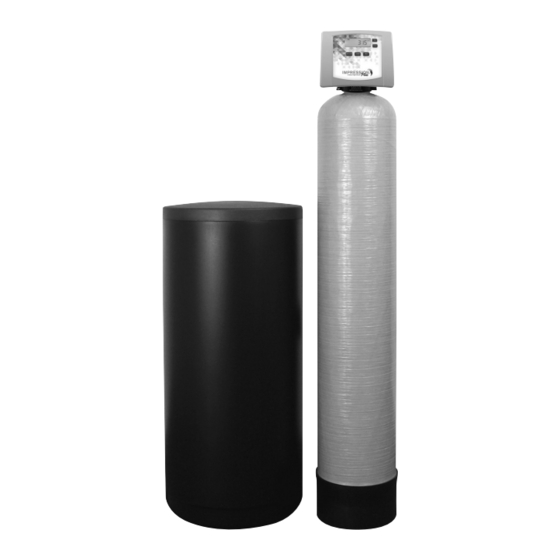
Water Right IMP-844 Installation Instructions And Owner's Manual
Impression plus series metered water softeners
Hide thumbs
Also See for IMP-844:
- Installation instructions & owner's manual (32 pages) ,
- Installation instructions & owner's manual (28 pages) ,
- Installation instructions & owner's manual (32 pages)
Advertisement
Table of Contents
- 1 Table of Contents
- 2 Preinstallation Instructions for Dealers
- 3 Bypass Valve
- 4 Installation
- 5 Programming Procedures
- 6 Operating Displays and Instructions
- 7 Start-Up Instructions
- 8 Troubleshooting Guide
- 9 Replacement Parts
- 10 Installation Fitting Assemblies
- 11 Specifications
- 12 Warranty
- 13 Quick Reference Guide
- Download this manual
Advertisement
Table of Contents

Subscribe to Our Youtube Channel
Related Manuals for Water Right IMP-844


Summary of Contents for Water Right IMP-844
- Page 1 Impression Plus Series ® Metered Water Softeners For Models: • IMP-844 • IMP-948 • IMP-1044 • IMP-1054 • IMP-1248 • IMP-1354 For Cabinet Models: • IMPC-835 • IMPC-935 • IMPC-1035...
-
Page 2: Table Of Contents
TABLE OF CONTENTS Preinstallation Instructions for Dealers ......3 Bypass Valve ..........3-4 Installation . -
Page 3: Preinstallation Instructions For Dealers
PREINSTALLATION INSTRUCTIONS FOR DEALERS: The manufacturer has preset the water treatment unit’s sequence of cycles, cycle times, salt dose, exchange capacity and salt dose refill time. The dealer should read this page and guide the installer regarding hardness, day override, and time of regeneration, before installation. - Page 4 1. NORMAL OPERATION POSITION: The inlet and outlet handles point in the direction of flow indicated by the engraved arrows on the control valve. Water flows through the control valve for normal operation of a water softener. During the regeneration cycle this position provides regeneration water to the unit, while also providing untreated water to the distribution system (Fig.
-
Page 5: Installation
INSTALLATION: GENERAL INSTALLATION & SERVICE WARNINGS The control valve, fittings and/or bypass are designed to accommodate minor plumbing misalignments. There is a small amount of “give” to properly connect the piping, but the water softener is not designed to support the weight of the plumbing. Do not use Vaseline, oils, other hydrocarbon lubricants or spray silicone anywhere. - Page 6 6. INLET/OUTLET PLUMBING: Be sure to install bypass valve onto main control valve before beginning plumbing. Make provisions to bypass outside hydrant and cold hard water lines at this time. Install an inlet shutoff valve and plumb to the unit’s bypass valve inlet located at the right rear as you face the unit.
- Page 7 9. BRINE TANK CONNECTION: Install the 3/8" O.D. polyethylene tube from the Refill Elbow to the Brine Valve in the brine tank. 10. OVERFLOW LINE CONNECTION: An overflow drain line is recommended where a brine overflow could damage furnishings or the building structure. Your softener is equipped with a brine tank safety float which greatly reduces the chance of an accidental brine overflow.
-
Page 8: Programming Procedures
PROGRAMMING PROCEDURES: 1. Set time of day: Time of day should only need to be set after extended power outages or when daylight saving time begins or ends. If an extended power outage occurs, the time of day will flash on and off indicating that the time should be reset. -
Page 9: Operating Displays And Instructions
2. Programming cont’d: STEP 4 – REGENERATION HOUR: The manufacturer has factory set 2:00 A.M. as the default. This is the hour of day for regeneration and can be reset by using + or — buttons. “AM/PM” toggles after 12. The default time is 2:00 a.m. (recommended for a normal household). Press to go to step 5. - Page 10 3. MANUAL REGENERATION: Sometimes there is a need to regenerate before the control valve calls for it. This may be needed if a period of heavy water use is anticipated or when the system has been operated without salt. • To initiate a manual regeneration at the next preset regeneration time, press and release MANUAL REGENERATION .
- Page 11 ERROR 5. ERROR MESSAGE: If the word “ERROR” and a number are alternately flashing on the display record the number and contact the dealer for help. This indicates that the control valve was not able to function properly. 6. BRINE TANK MAINTENANCE AND SALT: Refill the brine tank as necessary, making sure at least 1/3 of the brine tank is full at all times.
-
Page 12: Start-Up Instructions
START-UP INSTRUCTIONS: FLUSHING OF SYSTEM: To flush the system of any debris and air after installation is complete, please perform the following steps: 1. Rotate bypass handles to the bypass mode (see Fig. 2 of page 4). 2. Turn on inlet water and check for leaks in the newly installed plumbing. 3. - Page 13 5. Momentarily press again until the display reads “RINSE.” There should be a rapid flow to the REGEN drain. Unplug transformer to keep the valve in the “RINSE” position. Allow to run until steady, clear and without air. While the unit is rinsing, load the brine tank with water softener salt (refer to page 9, Brine Tank Maintenance and Salt).
-
Page 14: Troubleshooting Guide
TROUBLESHOOTING GUIDE: PROBLEM CAUSE CORRECTION A. No power at electric outlet A. Repair outlet or use working outlet B. Control valve power adapter not plugged into B. Plug power adapter into outlet or connect outlet or power cord end not connected to PC power cord end to PC board connection board connection 1. - Page 15 PROBLEM CAUSE CORRECTION A. Turn bypass handles to place bypass in A. Bypass valve in bypass position service position 7. Control valve does not B. Meter is not connected to meter connection on B. Connect meter to three pin connection labeled regenerate automatically PC board METER on PC board...
- Page 16 TROUBLESHOOTING GUIDE cont’d: PROBLEM CAUSE CORRECTION A. Injector is plugged A. Remove injector and clean or replace B. Faulty regenerant piston B. Replace regenerant piston C. Regenerant line connection leak C. Inspect regenerant line for air leak 12. Control valve fails to D.
- Page 17 PROBLEM CAUSE CORRECTION A. Check motor connections then Press NEXT and REGEN buttons for 3 seconds to resynchronize A. Motor failure during a regeneration software with piston position or disconnect power supply from PC board for 5 seconds and then reconnect. 16.
-
Page 18: Replacement Parts
REPLACEMENT PARTS: FRONT COVER AND DRIVE ASSEMBLY Item No. Part No. Description Qty. CV3540-A Black Impression ® cover CV3540-W-A Gray Impression ® cover CV3540P-A Black Impression Plus ® cover CV3540P-W-A Gray Impression Plus ® cover CV3107-1 Motor CV3106-1 Drive bracket & spring clip CV3579WI PC board, CC CV3110... - Page 19 REPLACEMENT PARTS: PISTON ASSEMBLY Item No. Part No. Description Qty. CV3005 1" spacer stack assembly CV3430 1.25" spacer stack assembly CV3004 Drive cap assembly CV3135 O-ring 228 CV3011 1" piston assembly downflow NOTE: For Impression Plus CV3011-01 1" piston assembly upflow ®...
- Page 20 REPLACEMENT PARTS: BYPASS VALVE Item No. Part No. Description Qty. CV3151 Nut, 1" quick connect CV3150 Split ring CV3105 O-ring 215 CV3145 Bypass rotor, 1" CV3146 Bypass cap CV3147 Bypass handle CV3148 Bypass rotor seal retainer CV3152 O-ring 135 CV3155 O-ring 112 CV3156 O-ring 214...
- Page 21 REPLACEMENT PARTS: INJECTOR ASSEMBLIES Item No. Part No. Description Qty. CV3176 Injector cap CV3152 O-ring 135 CV3177-01 Injector screen CV3010-1Z Injector assembly plug CV3010-1A A injector assembly, BLACK CV3010-1B B injector assembly, BROWN CV3010-1C C injector assembly, VIOLET D injector assembly, CV3010-1D CV3010-1E E injector assembly,...
- Page 22 REPLACEMENT PARTS: DRAIN LINE ASSEMBLY 3/4" Item No. Part No. Description Qty. CH4615 Elbow locking clip CPKP10TS8-BULK Optional insert, 5/8" tube Optional nut, 3/4" drain elbow CV3192 CV3158-01 Drain elbow, 3/4" NPT with O-ring CV3163 O-ring 019 CV3159-01 DLFC retainer assembly CV3162-007 0.7 DLFC for 3/4"...
- Page 23 REPLACEMENT PARTS: WATER METER & METER PLUG Item No. Part No. Description Qty. CV3151 Nut, 1" QC CV3003 Meter assembly, includes items 3 & 4 CV3118-01 Turbine assembly CV3105 O-ring 215 CV3003-01 Meter plug assembly Optional mixing valve CV3013 SERVICE WRENCH - CV3193-01 Although no tools are necessary to assemble or disassemble the valve, the Service Wrench, (shown in various positions on the valve) is...
- Page 24 REPLACEMENT PARTS: BRINE TANK ASSEMBLY Item No. Part No. Description Qty. CG2191- 84 Brine tank cover, injection molded WR CG2180 Brine tank cover, standard CH1095-01 Optional 18" diameter salt grid CH1080 Optional 24" diameter salt grid CG21833CB1C00 18" x 33" brine tank, black CG21840CB1C00 18"...
- Page 25 REPLACEMENT PARTS: CABINET BRINE TANK ASSEMBLY Item No. Part No. Description Qty. CG 2197-01 Salt and tank cover (must be ordered together CG2724HP-01 Windsor cabinet, white with black lids CH1090-01 Optional salt grid for 8" diameter tank and 4" brine well CH1090-02 Optional salt grid for 9"...
-
Page 26: Installation Fitting Assemblies
INSTALLATION FITTING ASSEMBLIES: 1" PVC MALE NPT ELBOW 3/4" & 1" PVC SOLVENT ELBOW Item Item Part No. Description Qty. Part No. Description Qty. CV3007 1" PVC male NPT elbow assembly CV3007- 01 3/4" & 1" PVC solvent elbow assembly CV3151 Nut, 1"... - Page 27 1-1/4" & 1-1/2" BRASS SWEAT 1-1/4" & 1-1/2" PVC SOLVENT Item Item Part No. Description Qty. Part No. Description Qty. CV3007- 09 1-1/4 & 1-1/2" brass sweat assembly CV3007- 07 1-1/4" & 1-1/2" PVC solvent assembly CV3151 Nut, 1" quick connect CV3151 Nut, 1"...
-
Page 28: Specifications
PERFORMANCE DATA SHEET: MODEL IMP- 844 IMP - 948 IMP -1044 IMP -1054 IMP -1248 IMP -1354 Rated Softener Minimum 13,000 @ 3.4 18,000 @ 4.5 18,000 @ 4.5 27,500 @ 7.0 36,000 @ 9.0 45,000 @ 11.5 Capacity:* Medium 16,500 @ 6.0 23,000 @ 9.0 23,000 @ 9.0... -
Page 29: Warranty
Water Conditioner Limited Warranty Congratulations. You have purchased one of the finest water treatment systems available. In the unlikely event of a problem due to defects in material and workmanship, we proudly warrant our water conditioners to the original owner, when installed in accordance with Water-Right ®... - Page 30 NOTES:...
-
Page 32: Quick Reference Guide
QUICK REFERENCE GUIDE: MANUAL REGENERATION GENERAL OPERATION NOTE: For softeners, When the system is operating, if brine tank does not one of three displays will be contain salt, fill with shown: time of day, gallons of salt and wait at least treated water available, two hours before or gallons per minute.
Need help?
Do you have a question about the IMP-844 and is the answer not in the manual?
Questions and answers