Table of Contents
Advertisement
Advertisement
Table of Contents

Related Manuals for HYT TC-518


Summary of Contents for HYT TC-518
-
Page 2: Table Of Contents
Safety Information......................2 Radio Overview ......................... 3 Software Specifications....................5 Circuit Description ......................8 CPU Pins .......................... 13 TC-518 Parts List 1 ......................16 Adjustment Description....................26 Troubleshooting Flow Chart................... 38 Disassembly and Assembly for Repair................41 Exploded View ......................... 46 TC-518 Parts List 2 ...................... -
Page 3: Introduction
The following safety precautions shall always be observed during operation, service and repair of this equipment. ◇ This equipment shall be serviced by qualified technicians only. ◇ Use only HYT supplied or approved batteries and chargers. ◇ To avoid electromagnetic interference and/or compatibility conflicts, turn off your radio in any area where posted notices instruct you to do so. -
Page 4: Radio Overview
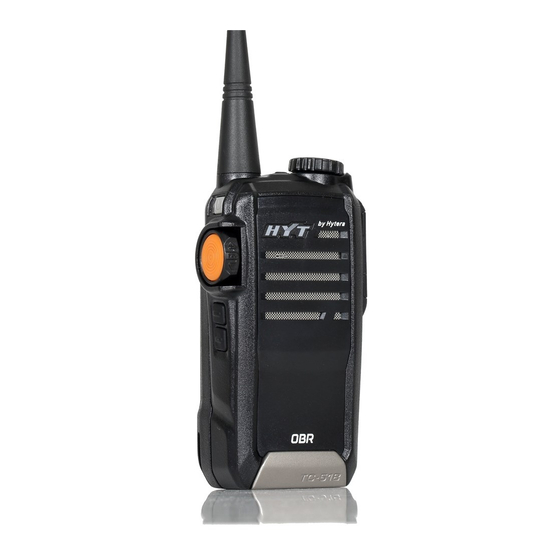
TC-518 Service Manual Radio Overview (1) Power On/Off Key (2) PTT (Push-to-Talk) Key (3) SK1 (programmable key) (programmable key) (5) Antenna (6) LED Indicator (7) Channel Selector Knob (8) Channel Indicator (9) Volume Control Knob (10) Microphone (11) Speaker (12) Battery Latch... - Page 5 TC-518 Service Manual Function Status of LED Indicator and Alert Tone Hold down the SK for 2 seconds to power on the source radio, and red LED flashes once. Enter the User Wired Clone Mode Power on the target radio directly.
-
Page 6: Software Specifications
TC-518 Service Manual The alert tone sounds once when the VOX feature is activated. The alert tone sounds twice when the VOX feature is disabled. Programmable Key Functions The following auxiliary functions are programmable for SK1 and SK2 by your dealer. - Page 7 TC-518 Service Manual 17. Wired Clone 18. Battery Strength Indicator 19. Manual Tuning 20. VOX and five selectable sensitivity levels Mode Description User Mode Conventional Communication Mode: the default mode after power-on. PC Programming Mode PC programming software will bring the radio into PC Programming Mode through communication based on specific communication protocol.
- Page 8 TC-518 Service Manual Access to Manual Adjust Mode: Hold down PTT, SK1 and Power On key to power on the radio for 2 seconds or longer. In case of a longer period (longer than 2 seconds), the orange LED (red LED plus green LED) glows, which indicates that the adjustment mode has been entered.
-
Page 9: Circuit Description
TC-518 Service Manual Circuit Description 1.1 General Principle Tx section: The modulated signal from MIC is directly sent to MCU chip (U604) for A-D conversion to digital signal, processing such as filtering, signal compression, encryption, pre-emphasis, Tx gain control and amplitude limiting, and restoration to modulated signal via D-A conversion. - Page 10 TC-518 Service Manual 1.2. Realization Methods for Basic Functional Modules 1.2.1 HF Sections Block diagram of PLL circuit: TX RF D401 D102 TXVCO TX SW BB179 MA2S077 Q104 2SK508NV RX SW D508 2SC5108 2SC5108 1st LO MA2S077 Q105 LOOP Q106...
- Page 11 TC-518 Service Manual The modulated carrier signal from Q109 is preamplified at Q402, and then enters Q403 for amplification of driver stage to drive the final power amplifier Q404, which further amplifies the input RF signal. The last amplified RF signal enters LC low-pass filter circuit (LPF) through diode D402, and then it is transmitted from the antenna after the high-order harmonics are removed by LPF.
- Page 12 TC-518 Service Manual 1.2.3 MCU Control, Signal Processing and Audio Amplification Circuit diagram of this section is shown as below: EXT_MIC Pre-emph Q201 Encryotion Compressor Limiter DTMF Q201 Expander Decryotion De-emph D210 DEMOD TONE(DTMF) CTCSS /CDCSS AF AMP TONE CTCSS...
- Page 13 TC-518 Service Manual 1.2.4 Power Supply Processing Block diagram of power supply is shown as below: POWER SW U603 Q601 Q602 XC6401FF37 Q603 7.4V VT_CTL U601 SAVE_CTL VR_CTL XC6209E502R Q606 U602 BATTERY XC6401FF55 V_SAVE Power Supply Section: The 7.4V battery voltage is converted to 5V DC voltage through LDO IC U601. One flow is converted to 4.5V DC voltage by double-channel LDO U602 to supply the Tx/Rx/VCO circuit, and the other flow is...
-
Page 14: Cpu Pins
TC-518 Service Manual CPU Pins PIN NO. PORT Pin Name Function UART TxD UART RxD APA_EN Speaker switch control, H: on; L: off. SAVE_CTL Power save control. In non-power-save status, it is set at high level. MIC_EN Check MIC connection (available for high level) - Page 15 TC-518 Service Manual Vdda VCC(3.3V) Power supply of analog circuit P72/AD2 Reserve P71/AD1 Noise detect P70/AD0 BAT_DET Battery strength detect XTAL0 OSC0 32.678KHz Main crystal oscillator Pin XTAL1 OSC1 PLL_CAP PLL_CAP PLL external capacitor (10nF) connection P03/COM3 PWR_ON/OFF Power output control...
- Page 16 TC-518 Service Manual P35/SEG21 Reserve P36/SEG22 Reserve P37/SEG23 Reserve P40/SEG24 Reserve P41/SEG25 EEPROM CLOCK P42/SEG26 EEPROM DATA P43/SEG27 Unlock detection of PLL circuit (H: lock; L: unlock) P44/SEG28 DATA PLL DATA P45/SEG29 PLL CLOCK P46/SEG30 PLL ENABLE Vssd Power grounding of digital circuit Vddd VCC(3.3V)...
-
Page 17: Tc-518 Parts List 1
TC-518 Service Manual TC-518 Parts List 1 TC-518 Parts List 1 (Main Board) Material No. Description Qty. Ref No. Print No. Chip resistor 0402 0 Ω J 1/16W 3001050000000 C622 Chip resistor 0402 0 Ω J 1/16W 3001050000000 R105 Chip resistor 0402 0 Ω J 1/16W... - Page 18 TC-518 Service Manual 3001051050000 Chip resistor 0402 1MΩ F 1/16W R629 3001051220000 Chip resistor 0402 1.2KΩ J 1/16W R117 3001051230000 Chip resistor 0402 12KΩ J 1/16W R503 3001051240000 Chip resistor 0402 120KΩ J 1/16W R123 3001051510010 Chip resistor 0402 150Ω F 1/16W...
- Page 19 TC-518 Service Manual 3001054790000 Chip resistor 0402 4.7Ω J 1/16W R317 3001054730000 Chip resistor 0402 47KΩ J 1/16W R109 3001054730000 Chip resistor 0402 47KΩ J 1/16W R125 3001054730000 Chip resistor 0402 47KΩ J 1/16W R127 3001054730000 Chip resistor 0402 47KΩ J 1/16W...
- Page 20 TC-518 Service Manual 3101050500010 Chip capacitor 0402 5PF B 50V C503 3101050500010 Chip capacitor 0402 5PF B 50V C508 3101050600010 Chip capacitor 0402 6PF B 50V C153 3101050600010 Chip capacitor 0402 6PF B 50V C170 3101050600010 Chip capacitor 0402 6PF B 50V...
- Page 21 TC-518 Service Manual 3101051030020 Chip capacitor 0402 0.01UF K 25V C538 3101051030020 Chip capacitor 0402 0.01UF K 25V C539 3101051030020 Chip capacitor 0402 0.01UF K 25V C543 3101051030020 Chip capacitor 0402 0.01UF K 25V C556 3101051030020 Chip capacitor 0402 0.01UF K 25V...
- Page 22 TC-518 Service Manual 3101052710000 Chip capacitor 0402 270PF J 50V C417 3101054700010 Chip capacitor 0402 47PF J 50V C312 3101054700010 Chip capacitor 0402 47PF J 50V C415 3101054710010 Chip capacitor 0402 470PF K 50V C101 3101054710010 Chip capacitor 0402 470PF K 50V...
- Page 23 TC-518 Service Manual 3101054740000 Chip capacitor 0402 0.47UF Z 6.3V C214 3101055600000 Chip capacitor 0402 56PF J 50V C412 3101055610000 Chip capacitor 0402 560PF K 50V C209 3101058200000 Chip capacitor 0402 82PF J 50V C313 3101060100010 Chip capacitor 0603 1PF B 50V...
- Page 24 TC-518 Service Manual 3210306220000 Multi-layer chip inductor 0603 22nH L402 3215006100010 Multi-layer chip inductor 0603 10nH L406 3213212102000 Multi-layer chip inductor 1008 1uH L404 3213212102000 Multi-layer chip inductor 1008 1uH L415 3213212102000 Multi-layer chip inductor 1008 1uH L513 3213212821000 Multi-layer chip inductor 1008 0.82uH...
- Page 25 Push button switch 3000/3600 PT036-D1S S603 4399090000000 Push button switch 3000/3600 PT036-D1S S605 5202020100040 Connector XF2M-2015-1A 20pin J602 3002996830040 Trimmer resistor ( 2.7*2.0*0.9) 68KΩ(+30%) VR101 3002996830040 Trimmer resistor ( 2.7*2.0*0.9) 68KΩ(+30%) VR600 7000190000010 TC-518 Cooler sheet 1.5MM Thick Brass 41005101001D0 TC-518U PCB...
- Page 26 TC-518 Service Manual TC-518 Parts List 1 (LED & Knob Board) Material No. Description Qty. Ref No. Print No. 3001056810000 Chip resistor 0402 680Ω J 1/16W R629 3101051020010 Chip capacitor 0402 1000PF K 50V C634 3101051020010 Chip capacitor 0402 1000PF K 50V...
-
Page 27: Adjustment Description
TC-518 Service Manual Adjustment Description Ⅰ. Function Key Overview (4) SK2 (programmable (1) Power On/Off Key (2) PTT (Push-to-Talk) Key (3) SK1 (programmable key) key) (5) Antenna (6) LED Indicator (7) Channel Selector Knob (8) Channel Indicator (9) Volume Control Knob... - Page 28 TC-518 Service Manual Ⅲ. Preparation Place the board to be tested on the test fixture (ensure good connection between each test point and the fixture), and connect the board to the power supply. IV. Adjustment Procedures 1. Operating Steps before Adjustment A.
- Page 29 TC-518 Service Manual 2. Description of Adjustment Item TC-518 Adjustment Items Wide Band Narrow Band Channel Adjustable Freq.1 Freq.2 Freq.3 Freq.4 Freq.5 Freq.1 Freq.2 Freq.3 Freq.4 Freq.5 Frequency Tx Section Tx Low Power Tx High Power CDCSS When programming, set this item (in adjustment mode) as 0.
- Page 30 TC-518 Service Manual adjustment frequencies under certain bandwidth and certain adjustment item. Add/Subtract the tuning value under certain bandwidth and certain adjustment item: Rotate the volume control knob upwards, and the adjustment value will increase by 1 under certain bandwidth and certain adjustment item;...
- Page 31 TC-518 Service Manual Test Adjustment Specifications / Item Condition Test Instrument Test point Part Method Remarks Adjust VR101 with ceramic tuning Tx Frequency Rotate the Channel Selector knob to CH1 and Communication Test ≤150Hz Antenna VR101 tool to control the center press PTT to transmit.
- Page 32 TC-518 Service Manual Make sure the antenna or load is connected before adjustment. Adjustment in the adjustment mode (Note: Test Adjustment Specifications / Item Condition Test Instrument Test point Part Method Remarks Rotate the Channel Selector Knob to CH2, and this function...
- Page 33 TC-518 Service Manual Rotate the Channel Selector Knob When the mode is entered, to CH4, and this function is rotate the volume control key to activated by default with low make slight adjustments until the Wide Band frequency. 650-700Hz CDCSS deviation meets the Press PTT key to switch between requirements.
- Page 34 TC-518 Service Manual Rotate the Channel Selector Knob to CH8 (wide band low frequency Wide Band Communication When the mode is entered, rotate 3.5± 0.1kHz by default). Press PTT to switch DTMF Test Set VOL+ the volume control knob to make between frequencies.
- Page 35 TC-518 Service Manual Rotate the Channel Selector knob to CH11 and SQL level 5 ON is set. Wide band and low frequency are Squelch level selected. Rotate the Channel (Level 5) Control Knob upwards and Communication -121dB downwards to activate this function.
- Page 36 TC-518 Service Manual Rotate the Channel Selector knob to CH12 and SQL level 5 OFF is set. Wide band and low frequency are Squelch level selected. Rotate the Channel Control (Level 5) Communication Knob upwards and downwards to -123dB Test Set Adjust the output signals of SSG to activate this function.
- Page 37 TC-518 Service Manual Red LED flashes with alarms when output voltage is Power Adjust the output voltage, and check less than 7.0V; Rotate the Channel Selector knob Power RX Low Voltage Threshold Digital Voltmeter supply the alarm level (red LED flashes and neither LED to CH13.
- Page 38 TC-518 Service Manual Appendix 1: Reference Values for TC-518 Source Radio Wide Band Narrow Band Test Items Freq. Freq. Freq. Freq. Freq. Freq. Freq. Freq. Freq. Freq.1 Tx Low Power Tx High Power CDCSS Balance (CH3) CDCSS Deviation CTCSS (67Hz) Deviation CTCSS (151.8Hz)
-
Page 39: Troubleshooting Flow Chart
TC-518 Service Manual Troubleshooting Flow Chart Tx Section Start Low Tx LED fails to Replace No sound power transmission glow/flash. D604. Normal Tx Check the Tx power supply? power supply. Check the LED of D604 Tx VCO Check the Tx... - Page 40 TC-518 Service Manual Rx Section Start No signal received . Check the Rx The Rx circuit is power supply normally supplied ? circuit. The Rx frequency Change the Rx Rx LED works normally? is set correctly? frequency. The Rx SQL level...
- Page 41 TC-518 Service Manual Start Normal power-on alert? The speaker Replace the works normally? speaker. Normal VCC Check U601, (operating voltage U602 and of MCU)? U603. X601 (clock crystal Replace X601. of MCU) works normally? Check the pin Other pins control...
-
Page 42: Disassembly And Assembly For Repair
TC-518 Service Manual Disassembly and Assembly for Repair Attaching/Removing the Battery Removing the Battery ① Turn off the radio. Hold the top part of the radio’ s body, and press the belt clip to make its bottom up. Lift the battery latch in the direction of the arrow by the notch at its bottom, as shown in Figure 1. - Page 43 TC-518 Service Manual Figure 4 Removing the Aluminum Chassis ① Remove the 2 screws at the bottom of the radio. ② Rotate and remove the antenna at the top of the radio. As shown in Figure 5. ③ Remove the fixed nuts by professional instruments.
- Page 44 TC-518 Service Manual Figure 7 ⑥ Unfasten the FPC connector on the main board, and uninstall the FPC. Attaching/Removing the Antenna Removing the Antenna ⑦Turn the antenna counter-clockwise until you can remove it. See Figure 8. Attaching the Antenna ①...
- Page 45 TC-518 Service Manual Attaching/Removing the Belt Clip Attaching the Belt Clip Loosen the screw on the belt clip first. Then fix the belt clip to the radio, and align the belt clip screw with the threaded hole on the radio, and then turn the screw clockwise to fasten it, as shown in Figure 10.
- Page 46 TC-518 Service Manual Removing the Earpiece/Microphone Loosen and remove the screws. Note: Using the radio with audio accessory may affect the waterproof performance of the radio. Attaching/Removing the Encoder Knob Cap Unclench cover of the encoder knob by a flathead screwdriver at the dent of the encoder knob (as shown below).
-
Page 47: Exploded View
TC-518 Service Manual Exploded View... -
Page 48: Tc-518 Parts List 2
TC-518 Service Manual TC-518 Parts List 2 Material No. Description Qty. (PCS) 6201658000010 Encoder knob cover 7102006000000 Machine screw 6000718000000 Encoder knob 7206007400000 Encoder switch nut 6100335000000 Antenna O-ring 7209002500000 Antenna nut 4400000029000 Antenna pedestal 6100361000000 Silicone rubber power on/off key... - Page 49 TC-518 Service Manual 6100323000000 Earpiece jack bracket 5001210000340 Speaker 1510051000000 TC-518 Front case kit 6300060000000 Decorative sheet, zinc alloy 6000749000000 Accessory jack cover 6000727000000 LED shade 8600510600100 TC-518 HYT PC label Remarks: Parts that are not marked with material number may vary with radio frequency band.
-
Page 50: Packing
TC-518 Service Manual Packing... -
Page 53: Tc-518 Level Diagram
TC-518 Level Diagram TC-510电平图 Rx Section -120dBm -122dBm -104dBm -108dBm -98dBm -103dBm -80dBm 143mVrms 143mVrms 0.5W C514 C514 C557 C557 C543 C543 Speaker Speaker XF503 U301 U604 U302 C438 C438 C510 C510 C528 C528 C556 C556 C319 C319 C321 C321... -
Page 54: Tc-518 Block Diagram
TC-518 Block Diagram TC-510原理方框图 TX SW Q404 D402 Q402 Q403 RD01 2SC4988 RQA0002 MA2Z077 EXT_MIC D501 U401 D502 Pre-emph NJM2904 MA2S077*2 J201 Encryotion Compressor Limiter RX SW DTMF Q201 D102 TXVCO D401 Expander Decryotion De-emph Q618 TX SW D210 BB179... -
Page 55: Tc-518 Schematic Diagram(Vco&Pll&Rf)
TC-518 Schematic Diagram (VCO & PLL & RF) TC-510U RFVCO&PLL HVC131 HVC131 D404 D404 V_SAVE C441 C441 C444 C444 ANT-TC900 ANT-TC900 R409 R409 C407 C407 C412 C412 L406 L406 C439 C439 R133 R133 C417 C417 C429 C429 C431 C431 C433... -
Page 56: Tc-518 Schematic Diagram(Led&Knob Board)
TC-518 Schematic Diagram TC-510 SmallBoard&MicphoneBoard (LED & Knob Board) R630 R630 S606 S606 R631 R631 R629 R629 VOL_SW VOL_SW D610 D610 D605 D605 D604 D604 C636 C636 C634 C634 SW601 SW601 C635 C635 1000P 1000P 1000P 1000P SW_channel SW_channel 1000P... -
Page 57: Tc-518 Schematic Diagram(Mcu&Power&Af)
TC-518 Schematic Diagram (MCU & Power & AF) TC-510U MCU&POWER&AF C327 C327 V_BAT 0.1U 0.1U TP610 TP610 TP609 TP609 TP608 TP608 U302 U302 C329 C329 C328 C328 TDA2822D TDA2822D RLED 1000P 1000P GLED SPK- R312 R312 VOL_UP R318 R318 C326... -
Page 58: Specifications
TC-518 Service Manual Specifications General VHF: 136-174MHz UHF: 400-470MHz Frequency Range 450-510MHz 350-390MHz Channel Capacity Channel Spacing 25/12.5 KHz Operating Voltage 7.4V DC Battery 1100mAh Li-Ion battery Battery Life (5-5-90 duty cycle) 9 hours above Operating Temperature -30℃~+60℃ Dimensions (H×W×D) - Page 59 TC-518 Service Manual HYT endeavors to achieve the accuracy and completeness of this manual, but no warranty of accuracy or reliability is given. All the specifications and design are subject to change without prior notice due to continuous technology development. Changes which may occur after publication are highlighted by Revision History contained in Service Manual.
Need help?
Do you have a question about the TC-518 and is the answer not in the manual?
Questions and answers