HYT tc-320 Service Manual
Hide thumbs
Also See for tc-320:
- Service manual (77 pages) ,
- User manual (24 pages) ,
- Service manual (68 pages)
Table of Contents
Advertisement
Quick Links
Advertisement
Table of Contents

Subscribe to Our Youtube Channel
Related Manuals for HYT tc-320


Summary of Contents for HYT tc-320
- Page 1 8 1 3 0 0 3 2 0 0 0 0 1 0...
-
Page 2: Table Of Contents
Contents Revision History ---------------------------------------------------------------------------------------------------------1 Copyright Information -------------------------------------------------------------------------------------------1 Disclaimer------------------------------------------------------------------------------------------------------------------------1 Introduction-----------------------------------------------------------------------------------------------------------------------2 Radio Overview-----------------------------------------------------------------------------------------------------------------3 Software Specifications------------------------------------------------------------------------------------------------------4 Circuit Description------------------------------------------------------------------------------------------------------9 CPU Pins-------------------------------------------------------------------------------------------------------16 Parts List 1---------------------------------------------------------------------------------------------------------20 Adjustment Description --------------------------------------------------------------------------------33 Troubleshooting Flow Chart--------------------------------------------------------------------------------------------43 Disassembly and Assembly-----------------------------------------------------------------------------------------------46 Exploded View------------------------------------------------------------------------------------------------------49 Parts List 2--------------------------------------------------------------------------------------------------------53 Packing Diagram--------------------------------------------------------------------------------------------------------55 PCB View-------------------------------------------------------------------------------------------------------56 Level Diagram------------------------------------------------------------------------------------------------------58 Block Diagram------------------------------------------------------------------------------------------------------59 Schematic Diagram--------------------------------------------------------------------------------------------------------60 Specifications-----------------------------------------------------------------------------------------------------------------66... -
Page 3: Revision History
Information Copyright Hytera and HYT are trademarks or registered trademarks of Hytera Communications Co., Ltd. (“Hytera”) in PRC and/or other countries or areas. Hytera retains the ownership of its trademarks and product names. All other trademarks and/or product names that may be used in this manual are properties of their respective owners. -
Page 4: Introduction
TC-320 Service Manual Introduction Manual Scope This manual is intended for use by qualified technicians only. -
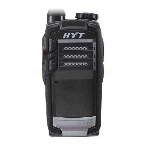
Page 5: Radio Overview
TC-320 Service Manual Radio Overview (1)PTT (Push-to-Talk) (4)Volume Adjust (2)SK (Side Key ) (3) Speaker Keys [+]/[-] (5) Microphone (6) Nameplate (7) Charging Terminal (8) Antenna (10) Channel/Status (11)Channel Selector (12)Charge (9)Power Switch Indicator Knob Indicator (13)Accessory Jack (14)Accessory Jack... -
Page 6: Software Specifications
TC-320 Service Manual Software Specifications Status Indications Operations/Functions LED Indications and Alert Tones Power on the source radio while holding down SK, To enter Wired Clone mode and the LED flashes red once. Turn on the target radio directly. The LED glows red during cloning process. - Page 7 TC-320 Service Manual The LED flashes red, and a low-pitched tone sounds Low Battery Alert every 10 seconds. The LED glows red during transmitting. When the TOT timer expires, the radio sounds beep Transmitting tones continuously. A TOT pre-alert tone sounds before the TOT timer expires.
- Page 8 The operation procedures are as follows: 1) Install PC programming software and its driver dedicated for TC-320 before your initial use. 2) Connect the USB port of PC with the Mini USB jack of the radio using a programming cable.
- Page 9 TC-320 Service Manual 2) During communication, LED of the source radio glows red, and LED of the target radio glows green. When communication finishes, LED of the source radio glows green and LED of the target radio goes out, indicating that both radios are ready for another cloning operation.
- Page 10 TC-320 Service Manual The LED solidly glows green when adjusting items CH10 to CH12. CH13 to CH16 are invalid and the LED goes out, indicating that no adjustment item is carried out. 4) To switch between wide and narrow bandwidth In adjusting a certain item, short press SK (the LED flashes orange to indicate valid press) to switch between wide and narrow bandwidth.
-
Page 11: Circuit Description
TC-320 Service Manual Circuit Description General Diagram The general circuit is composed of TX section, RX section, power supply circuit, control circuit and etc. The block diagram is shown in the figure below: CHARG D604 B302 J202 D602 CHARG B201... - Page 12 TC-320 Service Manual RX Section: RF signal received via the antenna is fed to the bandpass filter (composed of SAWF501 and SAWF502) to filter out unwanted out-of-band interference signal, and then amplified by LNA Q503. The amplified signal is then fed to the bandpass filter (SAWF503) to further filter out unwanted out-of-band interference signal.
- Page 13 TC-320 Service Manual Figure 2 The PLL circuit generates RF carrier signal for TX and the first local oscillator signal for RX. PLL: Step frequency of the PLL circuit is 6.25 KHz, 10.0 KHz or 12.5 KHz. In U101, the 21.25MHz reference oscillator signal is divided into 6.25 KHz, 10.0 KHz or 12.5 KHz reference frequencies via a...
- Page 14 TC-320 Service Manual W402 PRE AMP RF AMP RF AMP ANTENNA TX OUT Q401 Q402 Q403 R419 R420 R421 V_BAT U401 Q405 Q404 Figure 3 The modulated carrier signal from VCO is pre-amplified by Q104 and Q406, and controlled at D617 and D616.
- Page 15 TC-320 Service Manual Desired and undesired RF signals received via the antenna are fed to the bandpass filter (composed of SAWF501 and SAWF502) to filter out undesired out-of-band interference signal. Then the desired RF signal is amplified by LNA Q503, and goes through the bandpass filter ( to filter out undesired out-of-band interference signal.
- Page 16 TC-320 Service Manual 2.4.1 MCU Control Circuit MCU control circuit is composed of MCU, EEPROM, keys and etc. This section has the following functions: to initialize data of the radio and save data to EEPROM; to detect battery voltage and signals from external keys, LD and VOX, and to make response;...
- Page 17 TC-320 Service Manual POWER Q605 Q607 Q604 U602 DC-DC G602 BATTERY Q601 V_SAVE Q602 Figure 6 Power Supply Section: The 3.8V battery voltage is converted to two flows of 3.0V DC voltage by the LDO module (U602), that is, VCC and V_SAVE. VCC powers CPU while V_SAVE controls VT and VR.
-
Page 18: Cpu Pins
TC-320 Service Manual CPU Pins Pin No. Port Name Pin Name Function UART TXD UART RXD APA_EN To control the speaker; H: unmute, L: mute SAVE_CTL To control Power Save: it is at high level in non-Power-Save status EXT MIC... - Page 19 TC-320 Service Manual VSS_CLD Ground power supply for digital PA CLD_OUTM Reserve Reserved Vdd_CLD VCC (3.0V) Power supply for digital PA RF_CTRL To control RX frequency band; valid at high level (high frequency band); valid at low level (low frequency band)
- Page 20 TC-320 Service Manual P15/SEG5 Reserve Reserved P16/SEG6 Reserve Reserved P17/SEG7 Reserve Reserved P20/SEG8 P21/SEG9 To detect input from the encoder switch P22/SEG10 P23/SEG11 P24/SEG12 Reserve Reserved P25SEG13 Reserve Reserved P26/SEG14 Reserve Reserved P27/SEG15 Reserve Reserved P30/SEG16 Reserve Reserved P31/SEG17 Reserve...
- Page 21 TC-320 Service Manual P46/SEG30 PLL ENABLE Vssd Ground power supply for digital circuit Vddd VCC (3.0V) Power supply for digital circuit SW_P0 To control RX/TX, H: RX; L: TX (switch to VCO) SW_P1 TX_CTRL To control power supply for TX (transmit at high...
-
Page 22: Parts List 1
TC-320 Service Manual Parts List 1 Part No. Description Qty. Ref No. Print No. Remark 1 3001050000000 Chip resistor 0Ω J 1/16W (RoHS) L510 2 3001050000000 Chip resistor 0Ω J 1/16W (RoHS) R223 3 3001050000000 Chip resistor 0Ω J 1/16W (RoHS) R518 4 3001050000000 Chip resistor 0Ω... - Page 23 TC-320 Service Manual Part No. Description Qty. Ref No. Print No. Remark 43 3001051230000 Chip resistor 12KΩ J 1/16W (RoHS) R528 44 3001051530000 Chip resistor 15KΩ J 1/16W (RoHS) R406 45 3001051530000 Chip resistor 15KΩ J 1/16W (RoHS) R607 46 3001051540000 Chip resistor 150KΩ F 1/16W (RoHS) R422 47 3001051540000 Chip resistor 150KΩ...
- Page 24 TC-320 Service Manual Part No. Description Qty. Ref No. Print No. Remark 87 3001054710000 Chip resistor 470Ω J 1/16W (RoHS) R201 88 3001054710000 Chip resistor 470Ω J 1/16W (RoHS) R503 89 3001054720000 Chip resistor 4.7KΩ J 1/16W (RoHS) R112 90 3001054720000 Chip resistor 4.7KΩ J 1/16W (RoHS) R206 91 3001054720000 Chip resistor 4.7KΩ...
- Page 25 TC-320 Service Manual Part No. Description Qty. Ref No. Print No. Remark 131 3001066810010 Chip resistor 680Ω J 1/10W (RoHS) R625 132 3099080398000 Chip resistor 0.39Ω J 1/4W (RoHS) R419 133 3099080398000 Chip resistor 0.39Ω J 1/4W (RoHS) R420 134 3099080398000 Chip resistor 0.39Ω J 1/4W (RoHS)
- Page 26 TC-320 Service Manual Part No. Description Qty. Ref No. Print No. Remark 175 3101051500020 Chip capacitor 15PF J 50V (RoHS) C421 176 3101051200020 Chip capacitor 12PF J 50V (RoHS) C421 177 3101051500020 Chip capacitor 15PF J 50V (RoHS) C544 178 3101054790040 Chip capacitor 4.7PF B 50V (RoHS)
- Page 27 TC-320 Service Manual Part No. Description Qty. Ref No. Print No. Remark 219 3101054710010 Chip capacitor 470PF K 50V (RoHS) C522 220 3101054710010 Chip capacitor 470PF K 50V (RoHS) C524 221 3101054710010 Chip capacitor 470PF K 50V (RoHS) C553 222 3101054710010 Chip capacitor 470PF K 50V (RoHS)
- Page 28 TC-320 Service Manual Part No. Description Qty. Ref No. Print No. Remark 263 3101051020010 Chip capacitor 1000PF K 50V (RoHS) C617 264 3101051020010 Chip capacitor 1000PF K 50V (RoHS) C619 265 3101051020010 Chip capacitor 1000PF K 50V (RoHS) C620 266 3101051020010 Chip capacitor 1000PF K 50V (RoHS)
- Page 29 TC-320 Service Manual Part No. Description Qty. Ref No. Print No. Remark 307 3101051040060 Chip capacitor 0.1UF K 16V (RoHS) C441 308 3101051040060 Chip capacitor 0.1UF K 16V (RoHS) C519 309 3101051040060 Chip capacitor 0.1UF K 16V (RoHS) C520 310 3101051040060 Chip capacitor 0.1UF K 16V (RoHS) C528 311 3101051040060 Chip capacitor 0.1UF K 16V (RoHS)
- Page 30 TC-320 Service Manual Part No. Description Qty. Ref No. Print No. Remark 351 3210305220000 Multi-layer chip inductor 22nH J 300mA 0.42ohm (RoHS) L111 352 3210305220000 Multi-layer chip inductor 22nH J 300mA 0.42ohm (RoHS) L114 353 3210305220000 Multi-layer chip inductor 22nH J 300mA 0.42ohm (RoHS) L401 354 3210305220000 Multi-layer chip inductor 22nH J 300mA 0.42ohm (RoHS)
- Page 31 TC-320 Service Manual Part No. Description Qty. Ref No. Print No. Remark 395 3231351640000 Air-core inductor E2-0.35*1.6*4TL(RoHS) L413 396 3231351640000 Air-core inductor E2-0.35*1.6*4TL(RoHS) L414 397 3231351640000 Air-core inductor E2-0.35*1.6*4TL(RoHS) L501 398 3231351650000 Air-core inductor E2-0.35*1.6*5TL(RoHS) L409 399 3304060300050 Varactor HVC350BTRF-E (RoHS) D101 400 3304060300050 Varactor VR:15V 16.4pF/1VR 5.5pF/4VR(RoHS)
- Page 32 TC-320 Service Manual Part No. Description Qty. Ref No. Print No. Remark 439 4301080000090 Momentary contact switch 12VDC 0.05A (RoHS) SW605 440 3602999000000 Audio amplifier 1W 2.2~5.5V 62dB (RoHS) U301 441 3605008005070 Operational amplifier3~32V 300mW 100dB (RoHS) U401 442 3610999000060 SCM 100Pin (RoHS)
- Page 33 487 3101050100030 Chip capacitor 1PF B 50V (RoHS) C527 488 3101050100030 Chip capacitor 1PF B 50V (RoHS) C545 489 1616100001420 Built-in software for HYT conventioanl portable radio(RoHS) C545 490 3001051820000 Chip resistor 1.8KΩ J 1/16W (RoHS) R114 491 3001055620000 Chip resistor 5.6KΩ J 1/16W (RoHS) R117 492 3001057520000 Chip resistor 7.5KΩ...
- Page 34 TC-320 Service Manual Part No. Description Qty. Ref No. Print No. Remark 527 3001056810000 Chip resistor 680Ω J 1/16W (RoHS) R515 528 3404001000040 NPN transistor45V 100mA (RoHS) Q611 529 3604007000000 PLL IC 1.2GHZ(RoHS) U101 530 3001059120000 Chip resistor 9.1K J 1/16W (RoHS) R635 531 3001058220000 Chip resistor 8.2KΩ...
-
Page 35: Adjustment Description
TC-320 Service Manual Adjustment Description Required Test Instruments: Radio communication test set (HP8921) 1 set 10V/3A regulated DC power supply 1 set Digital voltmeter 1 set Ammeter 1 set Preparations: Place the board to be tested on the test fixture (please ensure good connection between each test point and the fixture), and connect the board to a power supply with DC voltage of 3.8V. - Page 36 TC-320 Service Manual The LED solidly glows green during the cloning process and goes out once it finishes. 3. Differences between Factory Clone Mode and User Clone Mode: (1) User Clone Mode: Only clone the data of user mode. Test parameters like adjustment frequencies, adjustment items and baseband parameters will not be cloned.
- Page 37 TC-320 Service Manual RX Items: VCO Lock Voltage (outside the mode), Squelch and RX Low Voltage Threshold. Specific Operations and Requirements: (1) Conventional Adjustment Items (outside the adjustment mode): TX Frequency Tolerance, VCO Lock Voltage. (Note: The configuration file has preset CH1, CH2 and CH3 as wide bandwidth with low, medium and high frequency respectively and CH4, CH5 and CH6 as narrow bandwidth with low, medium and high frequency respectively.
- Page 38 TC-320 Service Manual Adjust TC101 Rotate the with ceramic tuning tool until Channel 2.2V~2.6V Selector knob to the lock voltage RX VCO CH3. meets the Lock TC101 requirements. Voltage Rotate the Channel Check ≥0.5V Selector knob to CH1. (2) Adjustment in the Adjustment Mode (Note: Make sure the antenna or load is connected before adjustment;...
- Page 39 TC-320 Service Manual Short press PTT key rotate the to switch among Channel different frequencies Selector knob (low, medium and to save it. high) Rotate the Channel Communica Selector knob to tion test set CH3 and “wide BPF: Antenna bandwidth” and “low <20Hz~300...
- Page 40 TC-320 Service Manual Short press SK key to enter the “narrow Press [+] or [-] bandwidth” and key to make select low adjustments Narrow frequency. until the Bandwidt 350~550Hz CDCSS Short press PTT key deviation to switch among meets the different frequencies requirements.
- Page 41 TC-320 Service Manual On CH5, CH6 and key to make CH7, short press SK slight key to enter “narrow Narrow adjustment bandwidth”, and Bandwidt until the 350~550Hz short press PTT key CDCSS to switch among deviation different meets the frequencies.
- Page 42 TC-320 Service Manual to switch between <20Hz~15k Narrow wide narrow bandwidth. Bandwidt 1.5KHz AF:1kHz 13±3mV Rotate the Channel Selector Digital Power Adjust output ≤3.40V: knob to CH8. Voltage voltmeter Supply voltage of the Threshold Port power supply continuous to 3.42V, and...
- Page 43 TC-320 Service Manual Short press SK to enter “narrow Communicati band”. Press [+] on Test Set or [-] key to Squelch SSG:-118dB adjust squelch level(Level Narrow Same as level. Short press Bandwidth MOD:1KHz above. PTT key to -120±1dB DEV: 1.5KHz switch the Filter: 0.3~...
- Page 44 TC-320 Service Manual sample the 3.52V. current value. Communicati on Test Set SSG:-121dB High, medium, Wide -119dBm frequency Bandwidth MOD:1KHz or above out of the mode DEV: 3KHz Filter: 0.3~ Antenna 3KHz Sensitivity Earpiece Check Communicati Socket on Test Set...
-
Page 45: Troubleshooting Flow Chart
TC-320 Service Manual Troubleshooting Flow Chart Transmit Circuit Start Low TX LED fails to Replace No sound power transmission glow/flash. D602. Normal TX Check the TX power supply? power supply. Check the voice channel (Output ports of MIC,U501, LED of D602... - Page 46 TC-320 Service Manual Receive Circuit...
- Page 47 TC-320 Service Manual Start Normal power-on alert? The speaker Replace the works normally? speaker. Normal VCC (operating voltage of Check U602. MCU)? Clock crystal (X601) of MCU works Replace X601. normally? Check battery detect pin 40, Other pins control EEPROM detect...
-
Page 48: Disassembly And Assembly
TC-320 Service Manual Disassembly and Assembly Disassembly 1. Power off the radio 2. Remove the belt clip. 3. Remove the battery a. Push the battery latch upwards; b. Remove the battery cover; c. Take out the battery by lifting its bottom side. - Page 49 TC-320 Service Manual 5. Remove the Channel Selector knob, nut and waterproof ring a. Detach the Channel Selector knob cover; b. Unfasten the screw; c. Remove Channel Selector knob; d. Remove the nut and waterproof ring. 6. Disassemble chassis of the radio and the cover of PTT key.
- Page 50 TC-320 Service Manual 7. Disassemble the main PCB a. Remove the two fixing screws on the PCB; b. Remove the PCB and supporting ring of the Channel Selector knob. c. Beware of the speaker cable and the charging piece at the bottom.
- Page 51 TC-320 Service Manual 整机充电极片 Charging piece 2. Assemble the chassis a. Attach the cover of PTT key. b. Attach the chassis of radio; c. Attach and secure the four fixing screws (Note: Control torsion force within 1.2-1.5kgf). 3. Assemble the nuts and Channel Selector knob on the top a....
- Page 52 TC-320 Service Manual 4. Assemble the antenna 5. Attach the battery a. Insert the battery; b. Attach the battery cover.
- Page 53 TC-320 Service Manual 6. Attach the belt clip...
-
Page 54: Exploded View
TC-320 Service Manual Exploded View 30 31... -
Page 55: Parts List 2
TC-320 Service Manual Parts List 2 Part No Items Qty (PCS). 6201658001010 Encoder knob cover (RoHS) 7102006000100 Machine screw M2.0*6.0mm 6000718100000 Encoder knob (RoHS) 7206007400000 Fixing nut of encoder switch (RoHS) 6100335000000 O_RING for antenna (RoHS) 6000737100010 Light guide (charge LED) (RoHS) - Page 56 TC-320 Service Manual Main PCB(RoHS) 5002230000010 MIC (RoHS) 6100111000010 MIC cover (silicone rubber) (RoHS) 7400077000000 MIC net (RoHS) 6000732001010 Front case (RoHS) 6300062001010 Decorative sheet (zink alloy) (RoHS) 6100365000000 PTT key (silicone rubber ) (RoHS) 6000735000020 PTT key (RoHS) Antenna (RoHS)
-
Page 57: Packing Diagram
TC-320 Service Manual Packing Diagram... -
Page 68: Specifications
TC-320 Service Manual Specifications General Specifications Frequency Range U1:400-420MHz, U2:450-470MHz Channel Capacity Channel Spacing 25 KHz /12.5KHz Operating Voltage 3.8V DC Battery 1700mAh Li-Ion battery Battery Life (5-5-90 Duty Cycle) ≥10 hours Operating Temperature -20℃~+55℃ Dimensions (H×W×D) 100mm×48mm×27mm (with standard battery, without antenna) Weight (with standard antenna &...
Need help?
Do you have a question about the tc-320 and is the answer not in the manual?
Questions and answers