Table of Contents
Advertisement
Advertisement
Table of Contents
Troubleshooting

Related Manuals for Topcon Net-G3A


Summary of Contents for Topcon Net-G3A
- Page 3 Rev A ©Copyright Topcon Positioning Systems, Inc. May, 2009 All contents in this manual are copyrighted by Topcon. All rights reserved. The information contained herein may not be used, accessed, copied, stored, displayed, sold, modified, published, or distributed, or otherwise reproduced without express written consent from Topcon.
- Page 4 ECO#3568...
-
Page 5: Table Of Contents
Station Site ..............2-2 Consider the Net-G3A Reference Station Application ..........2-2 Perform a Site Inspection for the Net-G3A Reference Station ........2-3 Installing Topcon Software ..........2-5 Installing PC-CDU ............ 2-6 Installing FLoader ............. 2-7 Installing the CF Card ............2-8 Installing the USB Mass Storage Device (UMS) .... - Page 6 MINTER Description and Configuration ......3-9 MINTER Operation ........... 3-16 Using the Web Interface ........... 3-18 Accessing the Net-G3A through the Web Interface .. 3-18 Understanding the Web Interface ......3-20 Building an Antenna Cabling System ......3-20 Receiver Setup as a Temporary Reference Station ..3-21 Step 1: Set up the Receiver ........
- Page 7 Obtaining Customer Support ........... 5-7 Phone ................. 5-7 E-mail ................ 5-7 Website ..............5-8 Appendix A Specifications ............A-1 Net-G3A Dimensions ............A-2 Receiver Specifications ........... A-3 General Details ............A-3 GNSS Board Details ..........A-7 Connector Specifications ..........A-9 Power Connector ............A-9 Serial RS232C Connectors ........
- Page 8 GPS Antenna Connector ..........A-12 1PPS Connector ............A-13 Event Marker Connector ..........A-13 External Frequency Connector ........A-14 CF Cards Compatible with the Net-G3A ......A-15 Appendix B Safety Warnings ........... B-1 General Warnings ............. B-1 Usage Warnings ............... B-2 Appendix C Regulatory Information ........
-
Page 9: Terms And Conditions
Terms and Conditions Preface Thank you for purchasing this Topcon product. The materials available in this Manual (the “Manual”) have been prepared by Topcon Positioning Systems, Inc. (“TPS”) for owners of Topcon products and are designed to assist owners with the use of the product, and its use is subject to these terms and conditions (the “Terms and Conditions”). - Page 10 Preface Bluetooth SIG, Inc. and any use of such marks by Topcon Positioning Systems, Inc. is used under license. Other product and company names mentioned herein may be trademarks of their respective owners. EXCEPT FOR ANY DISCLAIMER OF WARRANTY WARRANTIES IN AN APPENDIX OR A WARRANTY CARD ACCOMPANYING THE PRODUCT, THIS MANUAL AND THE RECEIVER ARE PROVIDED “AS-IS.”...
- Page 11 Terms and Conditions comply with any of the Terms or Conditions. You agree to destroy the Software and Manual upon termination of your use of the product. All ownership, copyright and other intellectual property rights in and to the Software belong to TPS. If these license terms are not acceptable, return any unused Software and Manual.
-
Page 12: Manual Conventions
CAUTION performance, data integrity, or personal health. Notification that an action will result in system damage, loss of data, loss of warranty, or personal WARNING injury. Under no circumstances should this action be DANGER performed. NET-G3A Operator’s Manual viii... -
Page 13: Chapter 1 Introduction
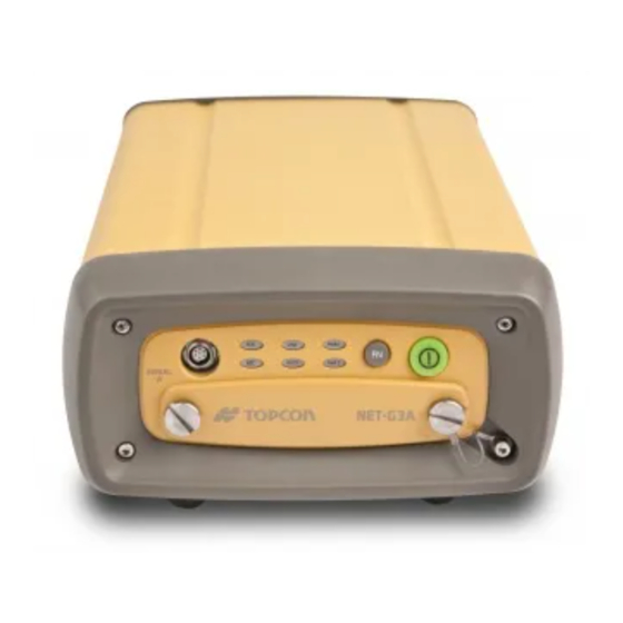
Introduction The Net-G3A receiver (Figure 1-1 on page 1-2) is a multi-frequency, GNSS receiver built to be the most advanced and convenient reference station receiver available today. The receiver is a dedicated permanent or semi-permanent reference station intended for precision markets. -
Page 14: Principles Of Operation
S TA R E C L IN R X /T Figure 1-1. Net-G3A Receiver Principles of Operation Whether based on a single reference station or a network of reference stations, static and mobile applications that use GNSS data from a high performance reference station benefit from the highest possible levels of accuracy and precision. -
Page 15: Calculating Absolute Positions
Principles of Operation • GLONASS – the Global Navigation Satellite System maintained and operated by the Russian Federation Ministry of Defense. For information on the status of this system, visit the Coordinational Scientific Information Center website. • GALILEO – an upcoming global positioning system maintained and operated by Galileo Industries, a joint venture of several European space agencies/companies working closely with the European Space Agency. -
Page 16: Calculating Differential Positions
• For post-mission applications, the simultaneous measurements from reference and remote stations are normally recorded to the receiver’s internal memory (not sent over communication link). NET-G3A Operator’s Manual... -
Page 17: Essential Components For Quality Surveying
Principles of Operation Later, the data is downloaded to a computer, combined, and processed. Using this technique, the spatially correlated errors—such as satellite orbital errors, ionospheric errors, and tropospheric errors—can be significantly reduced, thus improving the position solution accuracy. A number of differential positioning implementations exist, including post-processing surveying, real-time kinematic surveying, maritime radio beacons, geostationary satellites (as with the OmniSTAR service), and Satellite Based Augmentation Systems (WAAS,... -
Page 18: Receiver Overview
(for example, satellite health warnings). – Current ephemerides and almanacs. Receiver Overview The Net-G3A, with G3 tracking technology, represents the latest in GNSS-capable technology. This receiver provides greater value by virtue of its ability to keep up with changes in GNSS-signal enhancements through simple firmware upgrades, protecting your investment to the highest possible degree. - Page 19 Compact Flash memory or a UMS. This allows the operator to double check real-time results obtained in the field. The Net-G3A offers a unique collection of features and capabilities in a single design. They include: • 144 universal tracking channels •...
-
Page 20: Getting Acquainted
Although this is the standard configuration, the OAF must enable some of these features for proper operation. See “Option Authorization File (OAF)” on page 1-21 for details. The standard Net-G3A kit includes the Net-G3A, a set of cables, power supply, Topcon GPS+ software CD, Compact Flash card, and documentation. -
Page 21: Minter
Getting Acquainted • Flexibility in software applications that control and monitor the receiver’s behavior, including PC-CDU, TRU, and TopNET, as well as user-written applications. • Flexibility in the physical interface used to connect the receiver with various external devices, including computers, network devices, various sensors, frequency sources, etc. - Page 22 RX/TX PWR 2 REC LED RX/TX LED Figure 1-2. Net-G3A MINTER display the status of power supplied from the The PWR LEDs corresponding external or internal power source. • Solid Green – The receiver accepts power from an external power source connected to the corresponding PWR port.
- Page 23 Getting Acquainted • Red blinks – The receiver is charging the corresponding battery. • Off – The receiver consumes power from internal backup batteries or the receiver is turned off. displays the data recording status. See “The FN The REC LED button”...
- Page 24 If FN key mode is “Occupation mode switch” Green Release to start recording (Kinematic or Static post-processing occupation mode). Pressed for 5–8 Release to turn serial port A baud rate to seconds 9600 bps. Pressed for > 8 No light No function. seconds NET-G3A Operator’s Manual 1-12...
- Page 25 Getting Acquainted Table 1-1. FN Button Operations and REC LED Status (Continued) FN Key REC LED Status When data recording is on, and the FN key is... No free memory; hardware problem with data recording. If FN key mode is “LED blink mode switch” Green Data recording started (post-processing occupation mode undefined).
-
Page 26: Data And Power Ports
Introduction Data and Power Ports The Net-G3A has ports on both the front and back panels. has one port (Figure 1-3): Serial (7 pin ODU-MINI- The front panel SNAP) – used for communication between the receiver and an external device. This is the receiver’s serial port A. - Page 27 Getting Acquainted • Ethernet/USB port (12-pin ODU-MINI-SNAP) – used to connect the receiver to a computer or network via the adapter cable, which is also connected to the Ethernet/USB port. Connects to the Ethernet/USB port on the receiver Ethernet and USB ports Figure 1-4.
-
Page 28: Cf Card Slot
A Compact Flash card can be purchased at your local computer supply store. See “CF Cards Compatible with the Net-G3A” on page A-15 for a list of compact flash cards successfully tested with the Net-G3A. Before using any other CF cards, consult with Topcon customer support about compatibility. - Page 29 Always initialize the file system on the installed CF card before the first use. The initialization procedure is described in “Initializing File System” on page 4-12. STAT LINK PWR 1 RX/TX PWR 2 Card Slot Button CF Card Slot Figure 1-6. Net-G3A CF Card Slot P/N 7010-0935 1-17...
-
Page 30: Mounting Holes
Figure 1-7. Net-G3A Bottom Mounting Holes Cables and Power Supply The Net-G3A package includes standard communication and power cables for configuring the receiver and providing a power source to the receiver. Table 1-2 lists these cables. - Page 31 Getting Acquainted Table 1-2. Net-G3A Package Cables (Continued) Cable Description Cable Illustration Serial Cable Connects the receiver to an external device (controller or computer) for data transfer and receiver configuration. Body of connector is black. p/n 14-008005-03 Adapter Cable (with Ethernet...
-
Page 32: Other Kit Accessories
14-008099-01 Other Kit Accessories The standard accessories in the Net-G3A package includes a 512 MB CF memory card, a CD that contains standard Topcon GPS+ configuration software, a fuse, and receiver documentation. Figure 1-8. Net-G3A Included Accessories For more details on the optional accessories and packages available for the Net-G3A, contact your local Topcon dealer. -
Page 33: Option Authorization File (Oaf)
Option Authorization File (OAF) Option Authorization File (OAF) Topcon Positioning Systems issues an Option Authorization File (OAF) to enable the specific options that customers purchase. An Option Authorization File allows customers to customize and configure the receiver according to particular needs, thus only purchasing those options needed. - Page 34 Introduction Notes: NET-G3A Operator’s Manual 1-22...
-
Page 35: Pre-Setup Preparation
Once a location for the Net-G3A has been determined, you can begin installing the hardware and software required to configure and maintain the Net-G3A. After determining the application, use the selected software to configure the receiver for your application. -
Page 36: Determining The Reference Station Site
Establish_Operate_CORS.html), specifically the document titled Guidelines for New and Existing Continuously Operating Reference Stations (CORS). Consider the Net-G3A Reference Station Application Several decisions about the reference station application need to be determined before considering both the physical location and the receiver setup. -
Page 37: Perform A Site Inspection For The Net-G3A Reference Station
Perform a Site Inspection for the Net-G3A Reference Station When determining the location in which to place the Net-G3A, consider the relative safety of the physical location for both the receiver and personnel. Successful installation and operation of the reference station should meet the following guidelines: •... - Page 38 The site should provide and meet power specifications for the receiver and other installed equipment. The receiver should have direct access to a grounded outlet. The Net-G3A is designed to accept two external power inputs and automatically switch during power fluctuations to keep the receiver operational.
-
Page 39: Installing Topcon Software
CD-ROM drive. If you are downloading the program(s) from the website, then extract the program’s files into a folder on the computer’s hard drive. Refer to the Topcon Link documentation for details on installation and usage. If you purchased the TopNET reference station software suite, then refer to the corresponding documentation for installing and using this software and for configuring the Net-G3A using TopNET. -
Page 40: Installing Pc-Cdu
Positioning Systems. PC-CDU uses the GNSS Receiver Interface Language (GRIL) to configure various receiver settings and diagnose receiver performance. PC-CDU is available for free on the Topcon website (www.topconpositioning.com) or the GPS+ CD. Computer requirements for PC-CDU are: Windows® 98 or newer and an RS-232C or USB port. -
Page 41: Installing Floader
Installing Topcon Software navigate to the location of the *.exe file. To uninstall PC-CDU, Select the file, and press Delete. Installing FLoader FLoader is a firmware loading program for the GPS board inside the receiver. FLoader is available for free on the TPS website (www.topconpositioning.com) or the GPS+ CD. -
Page 42: Installing The Cf Card
CF card. A CF card can also be purchased at your local computer supply store. Make sure to install the CF card prior to operating the Net-G3A. The door also provides quick access to the card for removal. To preserve data integrity, only install or remove the CAUTION CF card when the receiver is powered off. -
Page 43: Installing The Usb Mass Storage Device (Ums)
UMS device. The UMS provides a sleek and high-capacity storage solution for transferring raw data files from the receiver’s CF card. The Net-G3A supports flash-based UMS devices as well as hard drive-based UMS devices with USB 1.1/2.0 interface. A UMS device can be purchased at your local computer supply store. -
Page 44: Formatting The Ums Device
Pre-setup Preparation Formatting the UMS Device The NET-G3A requires an external UMS device formatted for the FAT32 file system. The UMS device can be formatted using the internal Disk Management application provided by Microsoft Windows; however, this application cannot create partitions larger than 32 GB. -
Page 45: Powering The Receiver
• Always use a grounded outlet. • Use a surge protector to protect connected electronics devices. The Net-G3A has two power ports and either port powers the receiver. To power on the Net-G3A: 1. Connect the power cable to the power supply unit. -
Page 46: Checking Power Status
Checking Power Status You can check the receiver’s power status using the PWR LEDs or available Topcon software. The power LEDs on the receiver indicate the following power status: • Solid Green – power within the acceptable range (6–28 V DC) is present on this PWR port and is being used to power the receiver. -
Page 47: Turning On/Off The Receiver
Charging the Backup Batteries The charging circuitry of the iBEST system automatically charges the backup batteries whenever the Net-G3A is plugged into an external power source via any PWR connector. The receiver has to be on to charge the batteries. -
Page 48: Collecting Almanacs And Ephemerides
• If the last known receiver position, stored in the NVRAM, is different from the present position by several hundred kilometers. • After loading a new OAF. • After loading new firmware. • After clearing the NVRAM. NET-G3A Operator’s Manual 2-14... -
Page 49: Connecting The Receiver And A Computer
Other software, such as FLoader, are used to update, maintain, or configure the components of a connected receiver. The Net-G3A uses the following types of cables to connect with a computer: • RS232 cable (See “Establishing an RS232 Cable Connection” on page 2-16.) -
Page 50: Establishing An Rs232 Cable Connection
S T A L IN R E C R X /T Rear Front Panel Panel Figure 2-6. Net-G3A Serial Ports 2. Press the power buttons on the receiver and computer to turn them on. NET-G3A Operator’s Manual 2-16... -
Page 51: Establishing A Usb Cable Connection
Ethernet/USB Connector USB Ports USB Cable Figure 2-7. Net-G3A USB Ports 2. Press the power buttons on the receiver and computer to turn them on. Establishing an Ethernet Connection Make sure the IP settings of the receiver have been configured before connecting the receiver and computer using an Ethernet connection. - Page 52 Pre-setup Preparation The Net-G3A and associated software have two Ethernet connection options using the Ethernet adapter from the Net-G3A kit and an Ethernet cable purchased from a computer supply store: • a direct connection – requires an Ethernet crossover cable •...
-
Page 53: Configuring An Ethernet Connection Using Pc-Cdu
Connecting the Receiver and a Computer Configuring an Ethernet Connection Using PC-CDU Before you can use the Ethernet option on a Net-G3A, the settings for this connection method need to be configured. You will need the following hardware/software components to use an Ethernet connection. - Page 54 • Timeout – 600 (default value). This parameter sets the amount of time in seconds the receiver allows an inactive connection to remain open. After this time, the receiver terminates the unused connection. NET-G3A Operator’s Manual 2-20...
- Page 55 Connecting the Receiver and a Computer 6. For network connections, configure FTP Settings (optional) with the following selections (Figure 2-9): • TCP port – 21 (default value). This is the port on which the receiver listens for an FTP connection. The receiver allows up to five FTP connections at a time.
-
Page 56: Pc-Cdu Connection Parameters
Port connecting the computer and receiver (typically COM1, COM2 for RS232) Baud Rate Communication rate between the receiver and the computer (usually 115200) Rec ID Receiver’s identification number RS232 Figure 2-10. PC-CDU Connection Settings – RS232 and USB NET-G3A Operator’s Manual 2-22... - Page 57 Connecting the Receiver and a Computer Table 2-2. PC-CDU Connection Parameters for Ethernet Parameter Direct Network Connection Direct Mode Port ETHR TCP port 8002 (default) Host name IP address assigned to the receiver Password Assigned during initial setup Figure 2-11. PC-CDU Connection Settings – Ethernet (Direct Example) P/N 7010-0935 2-23...
-
Page 58: Power Management
Pre-setup Preparation Power Management Topcon’s PC-CDU software provides an interface for various configuration, monitoring, and management functions for the receiver. For power management of the receiver, PC-CDU displays the current voltage for the power source. 1. Connect your receiver and computer. See “Connecting the Receiver and a Computer”... -
Page 59: Net-G3A Configuration And Setup
Net-G3A Configuration and Setup The Net-G3A is intended primarily for use as a permanent or semi- permanent GNSS Reference Station to establish networks supporting both real-time and post-processing applications. Observation data can be streamed through any port to any device capable of receiving and utilizing it, including TopNET Reference Station software. -
Page 60: Configuring The Receiver
• download files from the receiver’s memory • load a new OAF and other configuration files to a receiver The following is an example of a configuration for the Net-G3A as a Reference Station supporting internal data logging and real-time mobile unit support using a radio for transmission of GNSS correction data. - Page 61 Configuring the Receiver 2. Start PC-CDU, and connect to the receiver according to the settings described in “PC-CDU Connection Parameters” on page 2-22. Once a PC-CDU connection with the receiver has been established, the current communications settings—such as port name, baud rate (if applicable), and flow control (if applicable)— display in the lower-left corner of the main window of PC-CDU.
- Page 62 Net-G3A Configuration and Setup 4. Click Set all parameters to defaults (Figure 3-2). Figure 3-2. Set All Parameters to Defaults 5. Click the MINTER tab, configure the following settings (Table 3-1), and then click Apply (Figure 3-3). Table 3-1. Receiver Parameters for the MINTER Tab...
- Page 63 Configuring the Receiver Figure 3-3. Configure MINTER for Static Data Recording 6. Click the Positioning tab, make sure the Elevation mask is set to 5 (default value), and then click Apply. Figure 3-4. Configure Receiver Positioning – Elevation Mask 7. Click the Base tab, set the following parameters (Figure 3-5 on page 3-6), and then click Apply.
- Page 64 Net-G3A Configuration and Setup – Click Get from receiver. The reference geodetic coordinates specified on this NOTICE tab relate to the antenna L1 phase center. 8. Continue with step 8 on page 3-6 for RTK surveys or step 9 on page 3-7 for other configurations.
- Page 65 Configuring the Receiver Table 3-2. Receiver Parameters for the Ports Tab (Continued) Parameter Base Receiver Baud rate Select a baud rate to use for transmitting differential messages from the receiver board to the modem module. The baud rate must match the modem’s serial port speed. RTS/CTS Select to enable handshaking.
- Page 66 Net-G3A Configuration and Setup • Carrier multipath reduction – enable Figure 3-7. Configure Mulitpath Parameters 11. Click OK to save the settings and close the dialog box. Once the receiver is configured, the configuration will remain until you change it using PC-CDU or clear the NVRAM.
-
Page 67: Minter Description And Configuration
MINTER Description and Configuration MINTER Description and Configuration The Minimum INTERface (MINTER) consists of two keys (power and FN) that control the receiver’s operation, four LEDs that display the receiver’s operational status, and two LEDs that display the power status (Figure 3-8). STAT LED LINK LED Power LEDs... - Page 68 Net-G3A Configuration and Setup • Shows the status of post-processing mode (static or dynamic) when performing a Post-Processing Kinematic survey with the help of the FN key (REC LED). • Shows the power status for the receiver (PWR LEDs). Use PC-CDU to configure MINTER settings. The procedure below describes the most common settings;...
- Page 69 MINTER Description and Configuration • Always append to the file on page 3-12 • Files Creation mode on page 3-12 • Automatic File Rotation Mode (AFRM) on page 3-12 • FN key mode on page 3-13 • Initial data collection dynamic mode on page 3-14 •...
- Page 70 Net-G3A Configuration and Setup <prefix><month><day><sequential lowercase letter><numeric portion> The file name depends on both the file creation time (month and day) and additional letter and numeric suffixes to avoid confusion between files created on the same day. If you want new receiver...
- Page 71 MINTER Description and Configuration • Files (total) – a counter that specifies how many multiple log files must be created in AFRM until this mode automatically turns off. This counter decrements on every file rotation until its value becomes zero, then file rotation automatically stops. The counter initializes with AFRM.
- Page 72 Net-G3A Configuration and Setup dynamic, if it blinks orange, the current mode is static. For more details, see Table 1-1 on page 1-12 and refer to the PC-CDU Reference Manual. These radio Initial Data Collection Dynamic Mode parameter buttons specify the starting occupation type descriptor inserted at the beginning of receiver files logged.
- Page 73 MINTER Description and Configuration Table 3-3. Data Recording Parameter Behavior (Continued) Enabled Radio Button Results Before Power Failure Always No file Data logging will Data logging will A log file with a specified; not start when not start when default name will receiver data power is restored.
-
Page 74: Minter Operation
Net-G3A Configuration and Setup MINTER Operation press the power button (Figure 3-12). To turn on/off the receiver, • When turning on, press the power button until the MINTER’s LEDs briefly flash. • When turning off, press the power button until the PWR LEDs turn red, then release. - Page 75 MINTER Description and Configuration Each time you turn off or on data recording, either a new file opens or data appends to a particular file. See “Always Append to the File parameter” on page 3-12 and “Files Creation Mode parameter” on page 3-12 for information on setting these functions.
-
Page 76: Using The Web Interface
Net-G3A Configuration and Setup Using the Web Interface The Net-G3A includes a built-in Web server that allows you to configure and monitor the receiver via a Web user interface (or Web interface). The following Web browsers are recommended for accessing the receiver: •... - Page 77 Your communications will use SSL. 3. Log in through the Web interface by entering the login name and password in the appropriate fields. The default login and password are topcon. Login names and passwords are case-sensitive and can be up to 12 alphanumeric characters.
-
Page 78: Understanding The Web Interface
• Use only low-loss coaxial cables. For distances of up to 10 meters, it is recommended to use Topcon’s RG-58 cable. If a greater length is required (up to 30 meters), it is recommended to use Topcon’s RG-8 or LMR-400. -
Page 79: Receiver Setup As A Temporary Reference Station
Reference Station The typical permanent or semi-permanent Reference Station setup has the Net-G3A in a secure location with access to power and communication links as required. The antenna location has been surveyed very accurately and is free of signal obstructions and interference (RF, multipath, etc.). -
Page 80: Step 1: Set Up The Receiver
Step 1: Set up the Receiver 1. Place the receiver in the predetermined location. A sturdy shelf or out-of-the-way table may be a convenient spot. See “Net-G3A Dimensions” on page A-2 for measurement details regarding the placement of NOTE screw holes for a permanent mount. -
Page 81: Step 2: Measure Antenna Height
Receiver Setup as a Temporary Reference Station To Grounded Power Outlet To Power Port 1 To GPS Antenna To GPS Antenna Port S TA LI N R E C R X /T Figure 3-17. Mount Receiver and Connect Cables Step 2: Measure Antenna Height The location of the antenna relative to the point being measured is very important for both surveys in which the elevation of the point is important and in surveys for horizontal location only. - Page 82 Net-G3A Configuration and Setup • Model of the antenna used Antennas have two types of measurements: • Vertical – measured from the marker to the antenna reference point (ARP) located on the bottom of the antenna at the base of the mounting threads.
-
Page 83: Step 3: Collect Data
Receiver Setup as a Temporary Reference Station Reference Surface for Offset Measurements Figure 3-18. Measure Antenna Height – Example Step 3: Collect Data See the remaining sections in this chapter for more information about collecting data. 1. Turn on the receiver. The STAT (status) light LED blinks red at first. -
Page 84: Stopping Data Logging
Net-G3A Configuration and Setup started. The REC LED blinks each time data is saved to the memory. Use PC-CDU to configure data logging. See “MINTER Description and Configuration” on page 3-9 or refer to the PC-CDU Reference Manual. Stopping Data Logging Stop logging data when you need to move the receiver, download data, or perform maintenance functions. -
Page 85: Analyzing Signal-To-Noise Ratio
After the survey completes, data the receivers collect can be downloaded onto a computer and processed using post-processing software (for example, Topcon Tools). Analyzing Signal-to-Noise Ratio Knowing the strength and reliability of the ranging signal transmitted from the satellites will help determine the quality of the satellite signals. -
Page 86: Using The Anti-Jamming Suppressor (Ajs)
If you have any problems or questions on using the Net-G3A with these devices, contact your local Topcon dealer. For contact information, visit the TPS website at: http://www.topconpositioning.com/static/dealer_pointer.php... -
Page 87: Receiver And File Maintenance
Also, the memory card holds a finite amount of files and information, so downloading data prevents files from being lost. The following steps use PC-CDU to download files, but any Topcon receiver management software can be used. P/N 7010-0935... -
Page 88: Downloading Data Files To A Computer
Connect (Figure 4-1 on page 4-2). Figure 4-1. Connection Parameters – RTS/CTS Handshaking 3. Click File File Manager, and then click the Download path tab on the File Manager dialog box (Figure 4-2). Figure 4-2. Find Files to Download NET-G3A Operator’s Manual... - Page 89 Downloading Data Files from an Installed Memory Card 4. Navigate to or create (using the Create button) the folder in which to download and store files. 5. Click the Download files tab, and select the file(s) to download (Figure 4-3 on page 4-3). To select multiple files, hold down the shift key and click on sequential files to select several files at once, or hold down the Ctrl key and click on individual files.
-
Page 90: Downloading Data Files To A Ums Device
3. Run PC-CDU. The Connection Parameters dialog box appears. If this dialog box is not open, then click File File Manager on the PC-CDU main page. 4. On the Connection Parameters dialog box, enable RTS/CTS handshaking and then click Connect (Figure 4-1 on page 4-2). NET-G3A Operator’s Manual... - Page 91 Downloading Data Files from an Installed Memory Card Figure 4-5. Connection Parameters – RTS/CTS Handshaking 5. Click File File Manager. 6. In the File Manager dialog box, click the USB Copy tab (Figure 4-6). Figure 4-6. USB Copy P/N 7010-0935...
- Page 92 A gray file name indicates that the file is selected and is ready for copying. A red file name indicates that the file cannot be copied for some reason (either an incorrect file name or the file is already on the UMS device). NET-G3A Operator’s Manual...
-
Page 93: Downloading Data Files From A Removed Memory Card
Topcon Link software. A CF card reader in or connected to the computer is required to access the data on the card. Before Topcon Link can read data on a Memory Card, the card must be formatted for Topcon devices. -
Page 94: Deleting Data Files From An Installed Memory Card
Receiver and File Maintenance 2. Navigate to the Topcon Memory Cards device directory, and click the device icon. 3. Click the desired, formatted memory card device icon. To download data files: After formatting the card, select and copy, or select and drag-and- drop, the desired files into a directory on the computer. - Page 95 Deleting Data Files from an Installed Memory Card 2. On the Connection Parameters dialog box, enable RTS/CTS handshaking (Figure 4-10). Figure 4-10. Connection Parameters – RTS/CTS Handshaking 3. Click File File Manager and select the file(s) to delete on the Download files tab (Figure 4-11 on page 4-10).
-
Page 96: Managing Receiver Memory
SS = 183 + 22*N When recording L1 and L2 data: SS = 230 + 44*N Table 4-1 shows the amount of receiver file memory required for the raw data measurements collected for an hour. The amount of memory NET-G3A Operator’s Manual 4-10... - Page 97 Managing Receiver Memory depends on the total number of GNSS satellites being tracked and used in position computation, and the recording interval. Table 4-1. Amount of Memory Required to Store a One Hour File Recording Interval (seconds) #SVs Single-frequency dual-system receiver Memory needed to record data 11 MB 1.1 MB...
-
Page 98: Initializing File System
When the receiver’s memory is initialized, information on the file system and physical memory displays. • Refresh – reloads the information. • Save to file – saves the files system and physical memory information to a text file. NET-G3A Operator’s Manual 4-12... -
Page 99: Setting Raw Data & Position Update Rates To 50 Hz
Setting Raw Data & Position Update Rates to 50 Hz Ok – closes the dialog box. Always initialize the file system on the installed CF card before the first use. It is recommended to CAUTION reinitialize the receiver file system on a regular basis. -
Page 100: Managing Receiver Options
The receiver’s OAF lists all enabled or disabled features. To determine if a feature is turned on or which features are available, check the receiver’s OAF using available Topcon receiver management software. The following steps use PC-CDU to view options. - Page 101 Managing Receiver Options • positive integer – the option is enabled • yes or no – the option is either enabled or disabled 3. When finished, click Exit on the Option Manager dialog box, and then click File Disconnect to disconnect from PC-CDU (and prevent conflicts with serial port management).
-
Page 102: Loading An Oaf
The following steps use PC-CDU to load the option file. For OAF related questions, e-mail TPS at options@topcon.com and include the receiver’s ID number. 1. Connect your receiver and computer. See “Connecting the Receiver and a Computer”... -
Page 103: Resetting The Receiver
Resetting the Receiver Resetting the Receiver If the receiver stops responding via buttons or software, then perform a hard reset. A hard reset should only be performed when the receiver is powered on and not otherwise responding. A hard reset simply cycles the receiver’s power. It does not erase information stored in the receiver’s NOTICE memory. -
Page 104: Clearing The Nvram
FN key. 4. Wait until the STAT and REC LEDs are green. 5. Wait until the STAT and REC LEDs blink orange. 6. Release the FN key while the STAT and REC LEDs blink orange. NET-G3A Operator’s Manual 4-18... -
Page 105: Using Pc-Cdu To Clear The Nvram
Changing Receiver Modes Using PC-CDU to Clear the NVRAM 1. Connect your receiver and computer. See “Connecting the Receiver and a Computer” on page 2-16 for this procedure. 2. Click Tools Clear NVRAM (Figure 4-16). Figure 4-16. Clear NVRAM with PC-CDU While the NVRAM clears, the REC LED flashes green and red;... - Page 106 15 minutes of powering on. • Green – ok • Orange – wait • Red – some tests failed 3. To switch back to normal mode, press the FN key three times within three seconds. NET-G3A Operator’s Manual 4-20...
-
Page 107: Sleep (Off) Mode
Use the latest firmware version, available for download from the TPS website (www.topconpositioning.com), to ensure your receiver has the most recent updates. The Net-G3A receiver must be loaded with NOTICE firmware version 3.4 or newer. Do not attempt to load firmware older than 3.4. - Page 108 You can download FLoader to your computer from the TPS website at www.topconpositioning.com. For more information, refer to the FLoader User’s Manual, also available on the Topcon website. See “Installing FLoader” on page 2-7 for installing FLoader on the computer.
- Page 109 Loading New Firmware 5. Click the Device tab, and then select Receiver from the Device Type drop-down list. Figure 4-18. Set Device Type 6. Click Get from Device for device information (Figure 4-18). 7. Click the Program tab, and select Soft Break Capture from the Capture Method drop-down list (recommended) (Figure 4-19).
- Page 110 Receiver and File Maintenance 10. Click File Exit. 11. Clear the receiver’s NVRAM (see “Clearing the NVRAM” on page 5-9) and update the almanac (see “Collecting Almanacs and Ephemerides” on page 2-23) after loading new firmware. NET-G3A Operator’s Manual 4-24...
-
Page 111: Chapter 5 Troubleshooting
WARNING hardware. Check This First! Before contacting Topcon support, check the following: • Check all external receiver connections carefully to ensure correct and secure connections. • Double check for worn or defective cables. -
Page 112: Troubleshooting Quick List
If you are using an external power source, the cable may be disconnected or damaged. Check that the cable is securely connected and undamaged. The receiver may have a defective power source. Make sure that the external power source is working properly. NET-G3A Operator’s Manual... -
Page 113: Receiver Problems
• Check that the cable connector is attached to the correct receiver port. • Unplug the cable, and then securely and properly reconnect it to the receiver. • See “Net-G3A Receiver” on page 1-8 and “Connector Specifications” on page A-9 for information about the receiver’s connectors. The cable is damaged. - Page 114 • Order a new OAF with the desired options activated to enable or extend validity of the corresponding receiver options. Contact your dealer or visit the Topcon website at www.topconpositioning.com for details. • Refer to the PC-CDU Reference Manual for a detailed description of options.
- Page 115 • Order a new OAF with the desired options activated to enable or extend validity of the corresponding receiver options. Contact your dealer or visit the Topcon website at www.topconpositioning.com for details. • Refer to the PC-CDU Reference Manual for a detailed description of options.
- Page 116 (see “Downloading Data Files from an Installed Memory Card” on page 4-1 and “Deleting Data Files from an Installed Memory Card” on page 4-8). • Use the AFRM feature. See “Automatic File Rotation Mode (AFRM) parameters” on page 3-12. NET-G3A Operator’s Manual...
-
Page 117: Obtaining Customer Support
Obtaining Customer Support Before contacting Topcon customer support about any problems with the receiver, consult your local Topcon dealer and also see “Check This First!” on page 5-1 for some solutions that may fix the issue. If, after taking the above steps, you still need assistance, contact Topcon customer support. -
Page 118: Website
Website The Topcon Positioning Systems website provides current information about Topcon’s line of products. The support area of the website provides access to frequently asked questions, configuration procedures, manuals, e-mail support, etc. -
Page 119: Appendix A Specifications
Specifications This Topcon product is a 144-channel GNSS receiver with an optional, removable CF memory card, a rugged aluminum housing complete with MINTER and cable connectors. Performance specifications assume a minimum of 6 GPS satellites above 15 degrees in elevation and... -
Page 120: Net-G3A Dimensions
Specifications Net-G3A Dimensions Figure A-1 shows the measurement dimensions for the Net-G3A receiver, including the placement of the screw holes. Dimensions are in inches. NOTE STAT LINK PWR 1 RESET PWR 2 3.75 4.960 4X Ø0.135 1.244 8-32 UNC 11.0 6.693... -
Page 121: Receiver Specifications
Table A-1 table lists the receiver’s general specifications. Table A-1. Receiver General Specifications Physical Enclosure Aluminum, IP67 rated extrusion Color Topcon Yellow and Topcon Grey Dimensions W:166 mm x H:93 mm x D:275 mm 6.54" x 3.66" x 10.83" Weight 3.0 kg (6.61 lbs) - Page 122 GPS antenna, 1PPS, Event Marker, Ext. Frequency MINTER Six external LEDs (see “LEDs” on page A-3 for details) ON/OFF control input (power button) Data logging control (FN button) Technology Advanced Multipath mitigation SBAS Adjustable PLL and DLL parameters Anti-Jamming Suppressor (AJS) NET-G3A Operator’s Manual...
- Page 123 Receiver Specifications Table A-1. Receiver General Specifications (Continued) Data Features Up to 50 Hz update rate for real time position and raw data (code and carrier) 10cm code phase and 0.1mm carrier phase precision RTCM SC104 version 2.1, 2.2, 2.3, and 3.0 I/O Multiple Base RTCM Geoid and Magnetic Variation models Different DATUMs support...
- Page 124 For L1+L2 – H: 3mm + 0.5ppm (x baseline length); V: 5mm + 0.5ppm (x baseline length) Kinematic, RTK For L1+ L2, L1 – H: 10mm + 1.0ppm (x baseline length) V: 15mm + 1.0ppm (x baseline length) NET-G3A Operator’s Manual...
-
Page 125: Gnss Board Details
Receiver Specifications Table A-1. Receiver General Specifications (Continued) DGPS Post processing: less than 0.25m (HRMS) DGPS/RTCM based: less than 0.25m (HRMS) Cold Start < 60 sec Warm Start < 10 sec Reacquisition < 1 sec GNSS Board Details Table A-2 lists the GNSS board’s general specifications. Table A-2. - Page 126 Cinderella days is an option that turns a single frequency, GPS receiver into a dual-frequency, GPS+GLONASS receiver for 24 hours every other Tuesday at GPS midnight. Refer to Topcon’s website at www.topconpositioning.com for more information and specific Cinderella day dates.
-
Page 127: Connector Specifications
Connector Specifications Connector Specifications The Net-G3A has the following connectors: • Power x 2 • GPS antenna • Serial RS232C: 1xODU and • 1PPS 3xDE-9 • Event marker • USB Host/Device • External Frequency • Ethernet Power Connector The power connector (Figure A-2) is a sealed receptacle, 5 pin, ODU part number G80F1C-T05QF00-0000. -
Page 128: Serial Rs232C Connectors
0.5 A Signal ground Clear to send Request to send Receive data Transmit data Not used The back panel serial RS232 connectors (Figure A-4) are a sealed receptacle, 9 pin, D-shell connector. Figure A-4. Serial RS232 Connector NET-G3A Operator’s Manual A-10... -
Page 129: Ethernet/Usb Connector
Connector Specifications Table A-5 gives the RS232 cable connector specifications. Table A-5. RS232 Connector Specifications Number Signal Name Details Not used Receive data Transmit data Not used Signal ground Not used Request to send Clear to send Not used Ethernet/USB Connector The Ethernet/USB connector is a 12-pin ODU-MINI-SNAP (Figure A-5). -
Page 130: Gps Antenna Connector
Bus power input GPS Antenna Connector The external antenna connector type is a N-type connector. Table A-7. External GPS Antenna Connector Specifications Type Signal Name Details Ant_IN RF input from LNA, 60 mA at 5.0 volts NET-G3A Operator’s Manual A-12... -
Page 131: 1Pps Connector
Connector Specifications 1PPS Connector The 1PPS connector is a coaxial female receptacle of BNC series, Kings Electronics part number KC-79-108. Table A-8. 1PPS Connector Specifications Connector BNC female Polarity Positive Pulse Signal level >=2 V, TTL into 50 Ohm load Pulse Width 3.3 msec (normal pulse);... -
Page 132: External Frequency Connector
BNC; 50 Ohm impedance Frequency 20 MHz Amplitude 0.6 Vp-p into 50 Ohm Waveform Sine wave Harmonics -19 dBc Spurious -70 dBc Input Connector BNC; 50 Ohm impedance Frequency 5/10/20 MHz Sensitivity 0.5...3 Vp-p into 50 Ohm NET-G3A Operator’s Manual A-14... -
Page 133: Cf Cards Compatible With The Net-G3A
CF Cards Compatible with the Net-G3A The following CF cards have been successfully tested with the Net-G3A and can be safely used with the receiver. Before using any other CF cards, consult with Topcon customer support about compatibility. Table A-11. Net-G3A CF Cards Compatibility List... - Page 134 Specifications Table A-11. Net-G3A CF Cards Compatibility List (Continued) Capacity (MB) Topcon part number Manufacture part number 22-006011-32 SSD-C32MI-3012 22-006011-128 SSD-C12MI-3012 22-006011-256 SSD-C25MI-3012 22-006011-512 SSD-C51MI-3012 1024 22-006011-001 SSD-C01GI-3012 White Electronics Designs 22-006011-128 WED7P128CFA7000I25 22-006011-256 WED7P256CFA7000I25 22-006011-512 WED7P512CFA7000I25 1024 22-006011-001 WED7P1G0CFA7000I25 NET-G3A Operator’s Manual...
-
Page 135: Appendix B Safety Warnings
General Warnings Safety Warnings General Warnings TPS receivers are designed for survey and survey related uses (that is, surveying coordinates, WARNING distances, angles and depths, and recording such measurements). This product should never be used: • Without the user thoroughly understanding this manual. -
Page 136: Usage Warnings
The owner should periodically test this product to ensure it provides accurate measurements. Inform TPS immediately if this product does not function properly. Only allow authorized TPS warranty service centers to service or repair this product. CAUTION NET-G3A Operator’s Manual... -
Page 137: Regulatory Information
FCC Compliance Regulatory Information The following sections provide information on this product’s compliance with government regulations for use. FCC Compliance This device complies with Part 15 of the FCC rules. Operation is subject to the following two conditions: 1. This device may not cause harmful interference, and 2. -
Page 138: Community Of Europe Compliance
For more detailed information about the take-back and recycling of this product, please contact your supplier where you purchased the product or consult. NET-G3A Operator’s Manual... -
Page 139: Appendix D Warranty Terms
1. The warranty against defects in a Topcon battery, charger, or cable is 90 days. P/N 7010-0935... - Page 140 Warranty Terms Notes: NET-G3A Operator’s Manual...
- Page 141 3-20 antenna cabling system overview 3-24 Antenna reference point Download See also ARP 4-1–4-4 files via PC-CDU 3-24 files via Topcon Link 3-12 Automatic file rotation mode 4-21–4-24 firmware indicators software Base configuration, static 3-3–3-8 Base station, configuration Beacon, DGPS overview 4-19–4-20...
- Page 142 File name prefix 2-15 USB driver Files 3-24 Internal antenna offset 4-10 delete 4-1–4-4 download via PC-CDU download via Topcon Link 4-21, 4-23 flash 4-21, 4-23 LINK 4-3, 4-6 select in PC-CDU 1-10 select in Topcon Link 1-11 REC blink pattern...
- Page 143 2-13 on/off Software ports FLoader switch 2-6, 3-3–3-8, 3-10, 3- PC-CDU 1-11 Power button 1-15 Power port Topcon Link 2-12 Power status 1-9, 2-5, 3-1, 3-2 TopNET 2-12, 2-24 via PC-CDU 1-9, 4-19 STAT LED 1-15 PPS port 1-9, 4-19–4-20...
- Page 144 Index 3-26 Static survey 3-26 Survey 3-21 Temporary reference station 4-19, B-2 Test 4-19–4-20 Topcon Link Topcon Link, download files TopNET, configure receiver Uninstall FLoader PC-CDU 2-22 USB connection parameters 2-15 USB driver 1-15 USB port Warnings general usage 3-18 Web interface NET-G3A Operator’s Manual...
- Page 146 Topcon Positioning Systems, Inc. 7400 National Drive, Livermore, CA 94550 800∙443∙4567 www.topconpositioning.com ISO 9001:2000 FM 68448 NET-G3A Operator’s Manual P/N: 7010-0935 Rev A 05/09 ©2009 Topcon Corporation All rights reserved. No unauthorized duplication.
Need help?
Do you have a question about the Net-G3A and is the answer not in the manual?
Questions and answers