Moxa Technologies NPort 5210 Quick Installation Manual
Nport 5200 series
Hide thumbs
Also See for NPort 5210:
- Quick installation manual (2 pages) ,
- User manual (194 pages) ,
- Quick installation manual (2 pages)
Table of Contents
Advertisement
Quick Links
5200 Series
Quick Installation Guide
Second Edition, December 2003
1. Overview
Welcome to the NPort 5200 Series, a compact palm-sized data
communication device that allows you to control RS-232 (NPort
5210/5230) or RS-422/485 (NPort 5230/5232/5232I) serial devices over a
TCP/IP-based Ethernet.
2. Package Checklist
Before installing the NPort 5200 Series products, verify that the package
contains the following items:
1 NPort 5200 2-port Serial Device Server
Documentation & Software CD
NPort 5200 Series Quick Installation Guide
Optional Accessories
DK-35A
DIN-Rail Mounting Kit (35 mm)
CBL-RJ45M9-150
RJ45 (8-pin) to DB9 (M) cable, 150 cm
CBL-RJ45F9-150
RJ45 (8-pin) to DB9 (F) cable, 150 cm
CBL-RJ45M25-150
RJ45 (8-pin) to DB25 (M) cable, 150 cm
CBL-RJ45F25-150
RJ45 (8-pin) to DB25 (F) cable, 150 cm
DIN-Rail Power Supply and Adapter
Notify your sales representative if any of the above items is missing or
damaged.
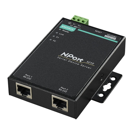
3. Hardware Introduction
As shown in the following figures, NPort 5210 has two 8-pin RJ45 ports,
both for the RS-232 interface, NPort 5230 has one 10-terminal terminal
block, with 5 pins used for one RS-232 port, and 5 pins used for one
RS-422/485 port, and NPort 5232 /5232I has one 10-terminal terminal
block, with all pins used for RS-422/485 ports.
—1—
Reset Button—Press the Reset button continuously for 5 sec to load
factory defaults: Use a pointed object, such as a straightened paper clip or
toothpick, to press the reset button. This will cause the Ready LED to
blink on and off. The factory defaults will be loaded once the Ready LED
stops blinking (after about 5 seconds). At this point, you should release
the reset button.
—2—
LED Indicators—The top panels of NPort 5200 have four LED
indicators, as described in the following table.
LED
LED
LED Function
Name
Color
Steady on:
Power is on and NPort 5200 is
booting up.
red
Blinking:
Indicates an IP conflict, or DHCP or
BOOTP server did not respond
properly.
Ready
Steady on:
Power is on and NPort 5200 is
functioning normally.
green
Blinking:
The device server has been located
by Administrator's Location
function
off
Power is off, or power error condition exists.
orange 10 Mbps Ethernet connection.
green 100 Mbps Ethernet connection.
Ethernet
off
Ethernet cable is disconnected, or has a short.
orange Serial port is receiving data.
green Serial port is transmitting data.
P1, P2
No data is being transmitted or received through
off
the serial port.
4. Hardware Installation Procedure
STEP 1: After removing NPort 5200 from the box, the first thing you
should do is connect the power adaptor. Connect the 12-30 VDC power
line with NPort 5200's terminal block, or connect the DIN-Rail power
supply with NPort 5200's terminal block.
STEP 2: Connect NPort 5200 to a network. Use a standard
straight-through Ethernet cable to connect to a Hub or Switch. When
setting up or testing NPort 5200, you might find it convenient to connect
directly to your computer's Ethernet port. In this case, use a cross-over
Ethernet cable.
STEP 3: Connect NPort 5200's serial port to a serial device.
—3—
Advertisement
Table of Contents

Related Manuals for Moxa Technologies NPort 5210


Summary of Contents for Moxa Technologies NPort 5210
-
Page 1: Quick Installation Guide
3. Hardware Introduction Ethernet cable. As shown in the following figures, NPort 5210 has two 8-pin RJ45 ports, STEP 3: Connect NPort 5200’s serial port to a serial device. both for the RS-232 interface, NPort 5230 has one 10-terminal terminal... - Page 2 Four cables are provided as optional accessories that can be used to (without ears) 2.64 × 3.95 × 1.37 in connect NPort 5210 to RS-232 serial devices. For your convenience, we Surge protection 15 KV ESD for serial port show precise cable wiring diagrams for each of the four cables.
Need help?
Do you have a question about the NPort 5210 and is the answer not in the manual?
Questions and answers