Avidyne FlightMax EX500 Pilot's Manual
Hide thumbs
Also See for FlightMax EX500:
- Pilot's manual (184 pages) ,
- Installation manual (124 pages)
Table of Contents
Advertisement
Quick Links
Advertisement
Table of Contents

Related Manuals for Avidyne FlightMax EX500


Summary of Contents for Avidyne FlightMax EX500
- Page 1 Multi-Function Display Pilot’s Guide 600-00078-000 Rev 09...
-
Page 3: System Configuration
All materials copyrighted including images that represent this software Copyright 2007 Avidyne Corporation. All rights reserved. System Configuration When contacting your dealer, Avidyne technical support, or logging onto MyAvidyne.com for the first time, please have your FlightMax EX500 serial number and Subscriber Communicator serial number... -
Page 4: About This Guide
Notes and Warnings Notes and Warnings provide guidance for the use of the EX500. Avidyne strongly suggests that you read all Notes and Warnings for your own safety. For example: Notes provide useful information about how to use the EX500. - Page 5 This manual assumes that the reader is an appropriately licensed pilot. Avidyne strongly recommends that you use the EX500 only under VFR conditions until you are very familiar with the EX500. If you have questions, please contact Avidyne at 800-284- 3963 (800-AVIDYNE) or 1-781-402-7400 before operating with the EX500 under IFR conditions.
- Page 6 The NOTAM information provided by the EX500 is for planning purposes only. Always consult official NOTAMS for the latest restrictions. Avidyne does not provide a complete list of NOTAMS. Local NOTAMS, most laser light NOTAMS, and any NOTAMS other than restricted airspace are not listed.
-
Page 7: Copyrights And Trademarks
(c) The Product has not been altered in any manner other than as previously authorized by Avidyne in writing; and (d) Repairs to the Product have not been made by anyone other than Avidyne or an Avidyne authorized service facility. - Page 8 Avidyne (or its affiliates) be responsible or liable for any damage of any nature whatsoever, including direct, indirect, incidental, consequential, special, loss of...
- Page 9 The foregoing four paragraphs define and limit Avidyne's sole responsibility and liability and purchaser's sole and exclusive remedies related to the product. Some jurisdictions may not allow the exclusion or limitation of warranties or liabilities, in which case the above limitations or exclusions, or some of them, may not apply in those jurisdictions...
- Page 10 This page intentionally left blank. FlightMax EX500 -viii- 600-00078-000 Rev 09...
-
Page 11: Table Of Contents
6 CMax Chart Pages (Optional) ....... 45 About Geo-Referenced Charts ..........45 CMax Chart Page ..............46 CMax Procedure Charts............47 CMax Chart Views..............50 Procedure Views ..............50 Airport Chart Views ............. 52 Selecting an Airport ..............54 600-00078-000 Rev 09 -ix- FlightMax EX500... - Page 12 Activating XM WX Satellite Weather ........91 Using Broadcast Datalink in Flight........92 About MultiLink ................92 Setting Up MultiLink ..............93 Optimizing your MultiLink Setup ..........94 Using MultiLink................97 NEXRAD Data ..............97 METAR Data ...............99 Datalink Messaging..............100 Sending a Datalink Message..........103 FlightMax EX500 600-00078-000 Rev 09...
- Page 13 Two-Way Datalink Messages ..........129 Broadcast Datalink Messages ..........131 TAWS Messages..............133 Radar Messages ..............135 Abbreviations and Definitions ..........137 Copyright..................107 AVIDYNE EXCLUSIVE LIMITED WARRANTY and LIMITATIONS ON LIABILITY..........108 Software License ................110 600-00078-000 Rev 09 -xi- FlightMax EX500...
- Page 14 List of Figures Figure 1.1 FlightMax EX500 System ..........1 Figure 1.2 Radar-Capable EX500 ............2 Figure 2.1 EX500 Map Page with Radar ..........7 Figure 2.2 METAR and AIR/SIG Buttons ...........8 Figure 2.3 Map Page - Terrain and Position........12 Figure 2.4 Map Page—Runways and Flight Plan Symbology..16 Figure 3.1 Traffic Advisory Message ..........20...
- Page 15 Figure 10.5 Two-Way Datalink and Broadcast NEXRAD Coverage 98 Figure 10.6 Broadcast Datalink, without Canadian METARs... 99 Figure 10.7 MultiLink with Canadian METAR Flags......99 Figure 10.8 Datalink Messaging Page ........... 101 Figure 10.9 Incoming Message Alert ..........104 600-00078-000 Rev 09 -xiii- FlightMax EX500...
- Page 16 Table 12.13 Traffic Messages ............125 Table 12.14 Lightning Messages..........126 Table 12.15 Two-Way Datalink Messages ........129 Table 12.16 Broadcast Datalink Messages ........131 Table 12.17 TAWS Messages............133 Table 12.18 Radar Messages ............135 Table 12.19 Avionics Abbreviations and Definitions.....137 FlightMax EX500 -xiv- 600-00078-000 Rev 09...
-
Page 17: Introduction
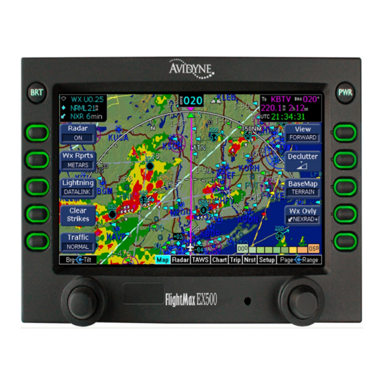
1 Introduction FlightMax EX500 is the most advanced situational awareness system in general aviation. Its display consolidates information from a variety of optional sensors in your aircraft (see Figure 1.1). TWX670/WX-500 Lightning Sensor Figure 1.1 FlightMax EX500 System Display information includes the following: Up to two GPS systems. -
Page 18: Starting The Ex500
1) BRT Button - Allows you to set the brightness level of the EX500. 2) PWR Button - Turns the power on and off. When you turn the power off, you need to hold the PWR button for a few seconds. The screen displays the power-down cycle. FlightMax EX500 600-00078-000 Rev 09... - Page 19 USB port. Do not pull too hard on the tab that attaches the plug to the EX500. This can separate the plug from the EX500 bezel. 600-00078-000 Rev 09 FlightMax EX500...
- Page 20 When other pages are in view, this knob provides cursor control. 10) Page Control Knob - Provides access to the EX500’s Map, Radar, TAWS, Chart, Trip, Nearest and Aux Pages. The active page is highlighted in the lower edge of screen. FlightMax EX500 600-00078-000 Rev 09...
-
Page 21: 2-Knob And 4-Knob Functionality
Radar Page (Optional), beginning on page 25 for more information. 4) Radar Tilt Control Knob - Controls the radar’s Tilt selection. If you have radar-capable EX500, see Chapter 4, Radar Page (Optional), beginning on page 25 for more information. 600-00078-000 Rev 09 FlightMax EX500... - Page 22 Introduction This page intentionally left blank. FlightMax EX500 600-00078-000 Rev 09...
-
Page 23: Map Page
1) Sensor Functions - Controls overlay and modes of available sensors. Buttons are displayed only for the sensors installed in your aircraft: Radar (if available) - Controls radar function selection. ■ On - Starts radar operation. ◆ Test - Initiates radar self-test function. ◆ 600-00078-000 Rev 09 FlightMax EX500... -
Page 24: Figure 2.2 Metar And Air/Sig Buttons
450nm from the current position. Lightning - Controls the display of lightning data on the map ■ (when interfaced with an Avidyne TWX670, an L3 WX-500 Stormscope, or a satellite-weather Broadcast Datalink receiver). FlightMax EX500... - Page 25 Declutter - Controls the density of symbols and labels ■ displayed on the map, from highest to lowest, based on settings defined on the Declutter Setup Page. See Declutter 600-00078-000 Rev 09 FlightMax EX500...
- Page 26 Datalink NEXRAD information on the map. 2-Way Datalink uses two-way messaging to send your flight plan to the Avidyne Network Operations Center (NOC), which then sends you only the data pertinent to your flight. - If Broadcast Datalink is installed and ◆...
- Page 27 Do not rely on the EX500 as your sole source for SUAs and TFRs. Availability of SUA and TFR Status data is subject to change and source availability. Before conducting flight operations, always confirm the active state of SUA and TFR locations with FAA Flight Service. 600-00078-000 Rev 09 -11- FlightMax EX500...
-
Page 28: Map Page Symbols-Terrain And Position
NEXRAD is the only Broadcast Datalink product on the Note: EX500 that displays the time since the product was created by the weather provider. Refer to the Trip page for information on all other weather products. FlightMax EX500 -12- 600-00078-000 Rev 09... -
Page 29: Table 2.1 Track Indicator Graphics
In the storm cell example to the right, the bottom storm cell, which includes the probability of hail, is moving NNE at 33 knots. The cell top is 35,000 feet high. 600-00078-000 Rev 09 -13- FlightMax EX500... - Page 30 A small cyan window will be displayed when this occurs. Terrain data is not displayed when that latitude of your aircraft is greater than 75 degrees (north or south). FlightMax EX500 -14- 600-00078-000 Rev 09...
- Page 31 The map terrain displayed on the EX500 is presented as the height above mean sea level (MSL) and does not indicate the height of the aircraft above the terrain. 600-00078-000 Rev 09 -15- FlightMax EX500...
-
Page 32: Map Page Symbols - Runways And Flight Plan
(when available) with respect to aircraft. See the Traffic Sensor User’s Manual for further details. 5) Obstacles - The EX500’s U.S. database contains the location and height of towers and other obstacles that are greater than FlightMax EX500 -16- 600-00078-000 Rev 09... - Page 33 Additional terrain awareness and alerting capability is available for the EX500 when interfaced with a Terrain Awareness and Warning System (TAWS). For more information, see Chapter 5, TAWS Page (Optional), beginning on page 37. 600-00078-000 Rev 09 -17- FlightMax EX500...
-
Page 34: Errors Displayed On The Map Page
2) The Skywatch system (if installed and a heading source is connected to the TAS). 3) A separate heading Synchro (if installed). 4) An Avidyne PFD. 5) The GPS (This would be a pass through. The GPS does not determine heading). -
Page 35: Traffic Mode And The Traffic Page (Optional)
Keep in mind that intruder traffic can maneuver at any time, and the current intruder track direction does not guarantee that the intruder will continue along that track. For traffic sensors without track information (e.g. TAS), traffic symbols are shown without the “stinger”. 600-00078-000 Rev 09 -19- FlightMax EX500... -
Page 36: Traffic Advisories
Traffic button on the Map Page. Target aircraft are displayed in standard format relative to current aircraft position. The available Traffic button modes are: Avidyne TAS600 series (including 9900BX), Skywatch, ■ and Bendix/King, TCAS - ABOVE, NORMAL, UNLIMTD, BELOW, and DSPLY OFF. -
Page 37: The Traffic Page
The EX500 displays up to five (5) non-bearing intruders below the airplane symbol, that is, traffic threats reported by the traffic sensor but without valid bearing. This serves as an alert that there is traffic, but its exact location cannot be determined. 600-00078-000 Rev 09 -21- FlightMax EX500... -
Page 38: Figure 3.2 Traffic Page
Pilot Guide. For TIS sensors, see the Aeronautical Information Manual. 2) Range Control - Turn the Range knob to select from the available ranges. For Traffic messages, see Traffic Messages on page 125. Note: FlightMax EX500 -22- 600-00078-000 Rev 09... -
Page 39: Traffic Symbols
If the intruder altitude and vertical speed are known, they are displayed alongside the intruder symbol. The number immediately above or below the traffic symbol indicates the relative altitude of the intruder to your position, in hundreds of feet. An arrow next to an 600-00078-000 Rev 09 -23- FlightMax EX500... -
Page 40: Tis Sensor Status
TIS data is not available at the current aircraft location. SBY - The TIS sensor is in standby mode. ● DATA FAIL - The TIS sensor has reported an internal fault. ● Traffic information is removed from display. FlightMax EX500 -24- 600-00078-000 Rev 09... -
Page 41: Radar Page (Optional)
See the user's guide for your radar for details. Radar is intended as a severe weather avoidance tool only. Do not use the EX500 to penetrate severe weather, thunderstorms, cells or lines of cells. 600-00078-000 Rev 09 -25- FlightMax EX500... -
Page 42: Map
OFF or in standby and your groundspeed (as received from the GPS system) falls below 20 Kts. If Auto Standby is enabled, the EX500 switches the radar to Standby automatically when ground speed falls below 20 Kts. FlightMax EX500 -26- 600-00078-000 Rev 09... - Page 43 Radar Off button is displayed. Similarly, if other buttons become free, additional radar buttons display, including Radar Test and Radar Standby. For radar messages, see Radar Messages on page 135. Note: 600-00078-000 Rev 09 -27- FlightMax EX500...
-
Page 44: Dedicated Radar Page
5) Stabilization Status (not shown) - Indicates the status of the radar's gyro stabilization. When stabilization is turned OFF, a STAB OFF screen annunciation appears. 6) Function Annunciation - The function annunciation (On, Test, Standby, Off) indicates the function status. FlightMax EX500 -28- 600-00078-000 Rev 09... - Page 45 10) The range scale includes the following ranges: Collins - 10, 25, 50, 100, and 250nm. ■ Bendix/King - 5*, 10, 20, 40, 80, 160, 240, and 320nm, ■ depending on radar/Type. 600-00078-000 Rev 09 -29- FlightMax EX500...
- Page 46 Radar Page (Optional) Based on recommendations made by the FAA and the radar manufacturer, Avidyne recommends the following safety procedures: • At startup, if the radar is not being used in flight, ensure that it is turned off. • Upon landing, if the radar is being used during the flight, switch to standby as soon as possible.
-
Page 47: Dedicated Radar In Ground Mode
4) Radar Off - Removes power from the radar. The antenna does not scan and no microwave energy is emitted. When the radar is off, the mode annunciator is set to OFF, and the moving scan indicator and radar echo returns are not present. 600-00078-000 Rev 09 -31- FlightMax EX500... - Page 48 9) Control - Switches the bottom left button and top right three button functions to control the Settings as described in Typical Radar on page 33. Push Control again to bring the top right three button functions back to “Mode” as described above. FlightMax EX500 -32- 600-00078-000 Rev 09...
-
Page 49: Typical Radar
(Map, for example). The Message text is, “Heavy Radar Echoes Beyond 60nm”. The Message warning is cancelled when you acknowledge it (by pressing the ACK button), or when the alert is eliminated by the radar sensor. 600-00078-000 Rev 09 -33- FlightMax EX500... -
Page 50: Vertical Profile Mode
However, they may be in another location due to the different configuration. A vertical profile annunciation (PROFILE) provides the current azimuth displayed on the screen, in degrees left (L), right (R) or centered. FlightMax EX500 -34- 600-00078-000 Rev 09... -
Page 51: Figure 4.5 Vertical Profile View
Vertical Profile Mode Figure 4.5 Vertical Profile view (Bendix/King RDS 84VP/86VP and RDR 2000/2100) 600-00078-000 Rev 09 -35- FlightMax EX500... -
Page 52: Radar Warnings
EX500. The MPEL boundary shown below does not guarantee protection against ignition of flammable materials or damage to sensitive electronic equipment exposed to microwave energy from your radar. Figure 4.6 Maximum Permissible Exposure Level FlightMax EX500 -36- 600-00078-000 Rev 09... -
Page 53: Taws Page (Optional)
5.1 TAWS Information Figure 5.1 TAWS Display as shown on 4-knob EX500 1) Range Annunciation - The range number indicates the currently selected range as selected by the Range knob (8). The supported 600-00078-000 Rev 09 -37- FlightMax EX500... - Page 54 During a terrain alert, threatening terrain is displayed in bright red and/or bright yellow. The elevation colors are not modified in this case, but continue to correspond to the colors that would appear FlightMax EX500 -38- 600-00078-000 Rev 09...
- Page 55 The TAWS display on the EX500 is an optional component of any TAWS-B installation and is intended only to enhance situational awareness. All terrain avoidance maneuvering must be predicated on indications from the installed TAWS system and not from the EX500. 600-00078-000 Rev 09 -39- FlightMax EX500...
- Page 56 100 feet or more, is not to be used for navigation. It is presented to provide the crew with additional situational awareness of true height above sea level upon which TAWS terrain alerting and display is based. FlightMax EX500 -40- 600-00078-000 Rev 09...
-
Page 57: Taws Operation
When a warning alert is triggered, the terrain or obstacle that caused the alert is displayed in bright red. In addition, a message describing the nature of the alert is presented in the message bar. 600-00078-000 Rev 09 -41- FlightMax EX500... -
Page 58: Figure 5.3 Terrain Warning Condition
EX500 automatically switches to the TAWS Display Page. The message bar is removed from the display when the EGPWS is no longer in alert status, or if you acknowledge the message from the TAWS Page. FlightMax EX500 -42- 600-00078-000 Rev 09... -
Page 59: Taws Reference
EGPWS, the system may still be initializing and the TAWS Page will display the text, “TAWS Initializing”, rather than the expected terrain. The EGPWS and TAWS Page will begin normal operation when the initialization is complete. 600-00078-000 Rev 09 -43- FlightMax EX500... - Page 60 TAWS Page (Optional) This page intentionally left blank. FlightMax EX500 -44- 600-00078-000 Rev 09...
-
Page 61: Cmax Chart Pages (Optional)
About Geo-Referenced Charts 6 CMax Chart Pages (Optional) CMax™ charts is an optional Avidyne feature. It includes the following: instrument approach procedures, arrivals, departures, airport diagrams, and various taxiway and airspace diagrams typical of Jeppesen printed charts. CMax requires that you have a valid chart data subscription from Jeppesen Sanderson, Inc. -
Page 62: Cmax Chart Page
Airport diagram for the current location when the GPS Ground Speed drops below 40 knots. The Chart Page shows the airport diagram of the current airport with ownship symbol for current aircraft position, if the airport diagram is geo-referenced. FlightMax EX500 -46- 600-00078-000 Rev 09... -
Page 63: Cmax Procedure Charts
5) Ownship - If the aircraft is on the chart, and the chart is geo- referenced, its location is displayed with the ownship symbol. The chart nominally remains fixed and the ownship symbol moves across the chart with aircraft movement. 600-00078-000 Rev 09 -47- FlightMax EX500... - Page 64 Day and Night modes. The Day display is black text on a white background, while the Night display is white text on a black background. Other colors such as water or shaded terrain are also adjusted between Day and Night modes. The EX500 starts FlightMax EX500 -48- 600-00078-000 Rev 09...
-
Page 65: Figure 6.2 Plan Procedure Chart (4-Knob)
(on Selection Page) and the chart is geo-referenced. If a flight plan is expected and does not appear, check that the correct airport and approach have been selected. 600-00078-000 Rev 09 -49- FlightMax EX500... -
Page 66: Cmax Chart Views
3 of 4 Profile Includes the profile view of the approach procedure. Note that in Figure 6.3, this chart is shown with the labels removed. 4 of 4 Minimums Shows the descent minimums for the approach. FlightMax EX500 -50- 600-00078-000 Rev 09... -
Page 67: Figure 6.3 Procedure Chart Views
The button legend shows the number of the current view as well as the total number of views available for that procedure (i.e., “1 of 4”, “2 of 4”, and so forth). Header View Profile View Minimums View Figure 6.3 Procedure Chart views 600-00078-000 Rev 09 -51- FlightMax EX500... -
Page 68: Airport Chart Views
Includes general chart information and communications frequencies. 3 of 4 Runways Shows runway information for the airport. 4 of 4 Departure Displays specific departure procedure information. Header View Runways View Departure View Figure 6.4 Airport Chart Views FlightMax EX500 -52- 600-00078-000 Rev 09... -
Page 69: Figure 6.5 Airport Departure Chart
Selection Page. Charts that cannot be split into smaller sections are shown as a complete chart, with the View button not displayed, since only one View type is available. Figure 6.5 Airport Departure chart 600-00078-000 Rev 09 -53- FlightMax EX500... -
Page 70: Selecting An Airport
The EX500 attempts to auto-complete an airport entry as the first characters are entered. Press the AutoFill button to immediately enter the destination airport. Only those airports within the subscriber’s coverage area are automatically completed. FlightMax EX500 -54- 600-00078-000 Rev 09... - Page 71 The current airport destination is not available in your chart ■ data coverage area. 6) Select Chart - Moves the active selection cursor from the Airport Entry Field to the Chart Selection list, described in Selecting a Chart on page 56. 600-00078-000 Rev 09 -55- FlightMax EX500...
-
Page 72: Selecting A Chart
Chart Page. Remember, when you press Display Chart the associated Airport diagram is also made available on the Chart Page automatically when a procedure chart is loaded. FlightMax EX500 -56- 600-00078-000 Rev 09... - Page 73 If you observe any of these, reload the CMax chart data using the CMax data loader. If problems persist, contact your dealer or Avidyne Technical Support. As pilot in command, it is your duty to have backup sources of data available.
-
Page 74: Chart Notams Page
Chart Selection Page. 2) Scroll knob - The Scroll knob scrolls the list of NOTAMs. If the list is longer than the screen area, scroll down to bring the remaining items into view. FlightMax EX500 -58- 600-00078-000 Rev 09... -
Page 75: Trip Page
The destination line is always displayed. All flight plans are from the GPS. A message, “No Flightplan Available”, is displayed if there is no flight plan entered, or if the GPS has failed. 600-00078-000 Rev 09 -59- FlightMax EX500... -
Page 76: Trip
Chart Icon - Indicates that a chart is available for the ◆ associated airport. An “I” on the icon indicates that at least one ILS approach chart is available for the associated airport, on the CMax Chart page. Chart icons FlightMax EX500 -60- 600-00078-000 Rev 09... - Page 77 METAR report might not be available and will not be displayed. The absence of displayed data does not mean that data is zero (for example, the absence of wind data does not necessarily mean that winds are calm). 600-00078-000 Rev 09 -61- FlightMax EX500...
- Page 78 Satellite in View - Displays the name of the satellite that ◆ is currently being used. Signal Strength/Signal Quality - Signal Status ◆ represents the overall health of the satellite signal. The higher these values are, the better the signal strength. FlightMax EX500 -62- 600-00078-000 Rev 09...
- Page 79 For Broadcast Status, the following information is displayed: Service Level - The Broadcast Datalink service level. If ◆ “Deactivation” is displayed, contact WSI\Sirius or XM. 600-00078-000 Rev 09 -63- FlightMax EX500...
- Page 80 WSI/Sirius winds aloft data includes the temperature at each wind reporting altitude. XM WX data does not display temperatures aloft. Rather, the XM Freezing Level forecast displays the expected altitude of the freezing level for the waypoint. FlightMax EX500 -64- 600-00078-000 Rev 09...
- Page 81 Trip Page. Use the GPS as the primary source of navigation information for approach procedures. Consult your avionics installation facility to determine if your EX500 is interfaced to the Garmin GNS-430 via ARINC 429 or RS-232. 600-00078-000 Rev 09 -65- FlightMax EX500...
-
Page 82: Airport Information Page
Step and Jump labels appear. Step - Scrolls the page one line. ■ Jump - Scrolls an entire page (or to the end of the list). ■ FlightMax EX500 -66- 600-00078-000 Rev 09... -
Page 83: Nearest Page (Nrst)
METAR reporting station for which an Instrument Procedure chart is available. An “I” on the icon indicates that at least one ILS approach chart is available. See Chart, below, for more information. 600-00078-000 Rev 09 -67- FlightMax EX500... - Page 84 Both types of Nearest Airport displays can be tailored by using the Note: Airport Filter button on the Aux - System Setup page. For example, this allows you to limit the lists to only certain types of airports or to certain minimum runway lengths. FlightMax EX500 -68- 600-00078-000 Rev 09...
-
Page 85: Airport Information Page
Step and Jump labels appear. Step - Scrolls the page one line. ■ Jump - Scrolls an entire page (or to the end of the list). ■ 600-00078-000 Rev 09 -69- FlightMax EX500... - Page 86 Nearest Page (NRST) This page intentionally left blank. FlightMax EX500 -70- 600-00078-000 Rev 09...
-
Page 87: Aux Page
Messaging and MultiLink setup options. For more information about MultiLink, see Using Multilink on page 105. If only Broadcast Datalink is installed, this button is not ■ displayed. The EX500 will be configured for Broadcast Datalink by the installer. 600-00078-000 Rev 09 -71- FlightMax EX500... - Page 88 10) System Time - Provides options for setting the system date and time and for tailoring the behavior of the menu button time-outs. 11) Scroll Knob - Controls the cursor to allow you to review all the messages in the message list. FlightMax EX500 -72- 600-00078-000 Rev 09...
-
Page 89: Airport Filter Setup
2) Surface - Selects the display of hard, soft and/or water surfaces. 3) Minimum Runway Length - Selects the minimum runway length in hundreds of feet (from 2,000 to 7,000) or selects all runway lengths. 600-00078-000 Rev 09 -73- FlightMax EX500... -
Page 90: Declutter Setup
The EX500 may limit the number of symbols displayed based Note: on the total symbol density. 3) Label - Checking the label box displays the navaid label along with the symbol. The labels show associated Navaid name or FlightMax EX500 -74- 600-00078-000 Rev 09... - Page 91 4) Range Dots - The dots represent the available map scales. A blue dot indicates that the object is displayed at that range. The vertical dash line indicates the map current scale. 600-00078-000 Rev 09 -75- FlightMax EX500...
-
Page 92: Data Block Setup
3) Data Block - Allows up to 3 lines of data for display. The data block resizes automatically based on the number of lines selected. The data block is not displayed if all the lines are set to “-Blank-.” FlightMax EX500 -76- 600-00078-000 Rev 09... -
Page 93: System Time Setup
Most RS232 GPS interfaces do not provide time data. Note: Auto - The system tries to set the time automatically by ■ obtaining data first from the GPS and then from the 2-Way Datalink system, if installed. 600-00078-000 Rev 09 -77- FlightMax EX500... - Page 94 5) Menu Timeout - Sets the amount of time that the button labels are displayed from the following choices (in seconds): Never, 2, 5, 10, 20, 30, 40, 50, 60. If “Never” is selected, the button labels do not time out. FlightMax EX500 -78- 600-00078-000 Rev 09...
-
Page 95: Datalink Configuration Page
2) Datalink Defaults - Press Datalink Defaults to reset the Datalink Setup options to the following values: Coverage Area - Flight Plan ■ Coverage Radius - 200 NM ■ NEXRAD Resolution - Medium ■ Request Interval - Normal Rate ■ 600-00078-000 Rev 09 -79- FlightMax EX500... - Page 96 Maximum Rate - Data is queued for delivery as soon as new ■ updates arrive at the NOC, up to 12 updates an hour (normally 4 – 12 updates an hour). FlightMax EX500 -80- 600-00078-000 Rev 09...
- Page 97 SUA and TFR locations with FAA Flight Service. 9) Save - Saves any changes made and return to the Aux Page. 10) Cancel - Press to return to the Main Setup menu without accepting any changes. 600-00078-000 Rev 09 -81- FlightMax EX500...
- Page 98 Aux Page This page intentionally left blank. FlightMax EX500 -82- 600-00078-000 Rev 09...
-
Page 99: Datalink (Optional)
Avidyne offers the following Datalink services for the EX500: Two-Way Datalink - An optional, 2-Way Datalink transceiver ● sends your flight plan to the Avidyne Network Operations Center (NOC), which then sends you only the data pertinent to your flight. Two-Way Datalink can provide the lowest-cost datalink by charging only for the data used. - Page 100 Map Page, Trip Page, and on both types of Nearest Airport Pages. They allow a “big-picture” view of general weather conditions in an area. The presence of a graphical METAR does not necessarily mean that the corresponding Text METAR is viewable. FlightMax EX500 -84- 600-00078-000 Rev 09...
- Page 101 Broadcast Datalink can provide lightning strike data, allowing the Map Page to add “Datalink” as a source of strike data that is controlled by the Lightning button. The actual weather products delivered depend on your satellite weather subscription plan. 600-00078-000 Rev 09 -85- FlightMax EX500...
-
Page 102: Using 2-Way Datalink
The intent of the boundary is to show clearly when there is actual weather in the area, versus when there might be weather in a given area but it is not displayed. FlightMax EX500 -86- 600-00078-000 Rev 09... -
Page 103: Loss Of Satellite Coverage
Your Satellite in view data field on the Trip Page indicates ● “NONE” (this is normal for brief periods during normal operations—usually no more than 5 minutes). All signal strength indicators are dashed (“- - -”). ● 600-00078-000 Rev 09 -87- FlightMax EX500... -
Page 104: Using Broadcast Datalink
EX500 Trip Page. Press the Display button until “↓Status” (Broadcast Datalink status) is shown, and carefully record your Serial Number. (Note that XM Radio does not use “I” (eye), “O” (oh), “S” or “F”.) Credit Card Information ● FlightMax EX500 -88- 600-00078-000 Rev 09... -
Page 105: Using Wsi Broadcast Weather On The Sirius Satellite Network
To verify that your receiver is activated, do the following: 1) Move your aircraft outside to an area with a clear view of the sky and power up both the EX500 and the Broadcast receiver. 600-00078-000 Rev 09 -89- FlightMax EX500... -
Page 106: Using Sirius Audio
Broadcast activation is recorded by the Avidyne Network Operations Center (NOC). If 24 hours pass before you can get to your aircraft, contact Avidyne to have another test signal sent to your aircraft. The EX500’s Service Level indication might take several... -
Page 107: Activating Sirius Audio
Broadcast receiver powered on for at least an hour. This ensures that the Broadcast activation is recorded by the Avidyne Network Operations Center (NOC). If 24 hours pass before you can get to your aircraft, contact XM Satellite Radio's Listener Care Center again or visit www.xmradio.com/activation... -
Page 108: Using Broadcast Datalink In Flight
NEXRAD is unavailable in a particular area for any reason, the hatched lines appear in that area. 10.6 About MultiLink Avidyne’s MultiLink features are available only if you have both 2- Way Datalink and Broadcast Datalink systems active. MultiLink offers the following features: Expanded Coverage—Broadcast Datalink only includes data for... -
Page 109: Setting Up Multilink
NOC to receive and acknowledge the Broadcast datalink signal. After you have activated the Broadcast receiver, log in to your account on www.MyAvidyne.com and click on Flight Center to set up your MultiLink account. 600-00078-000 Rev 09 -93- FlightMax EX500... -
Page 110: Optimizing Your Multilink Setup
Broadcast system. Since weather data will be transmitted whenever the selected Coverage Area extends outside of CONUS, be sure to select the appropriate Coverage Area. FlightMax EX500 -94- 600-00078-000 Rev 09... -
Page 111: Figure 10.3 Coverage Area For Broadcast Weather
2-Way Datalink usage and data availability: Expanded Coverage - If you have a Broadcast Datalink receiver ● installed, you must purchase service from WSI Sirius or XM WX Satellite Weather to activate the receiver. If you regularly fly 600-00078-000 Rev 09 -95- FlightMax EX500... - Page 112 Datalink Messaging and Flight Tracking available on all flights, you can de-select all weather types but leave MultiLink enabled. This will cause the system to use a minimum of 2-Way Datalink data on each flight for session management and position reporting. FlightMax EX500 -96- 600-00078-000 Rev 09...
-
Page 113: Using Multilink
2-Way Datalink. In this case, some very significant weather sat just outside the Broadcast NEXRAD area. With MultiLink, NEXRAD for your flight plan coverage area can extend far beyond the limits of Broadcast Datalink. 600-00078-000 Rev 09 -97- FlightMax EX500... -
Page 114: Figure 10.4 Broadcast Datalink Nexrad Coverage
Broadcast or from 2-Way Datalink. No specific action is required to choose between Datalink systems for this data. Figure 10.4 Broadcast Datalink NEXRAD Coverage Figure 10.5 Two-Way Datalink and Broadcast NEXRAD Coverage FlightMax EX500 -98- 600-00078-000 Rev 09... -
Page 115: Metar Data
Canadian METAR reports received via Broadcast Datalink. Note the expanded graphical METAR coverage in Canada provided by the MultiLink system in the following images: Figure 10.6 Broadcast Datalink, without Canadian METARs Figure 10.7 MultiLink with Canadian METAR Flags 600-00078-000 Rev 09 -99- FlightMax EX500... -
Page 116: Datalink Messaging
Do not use Datalink Messaging in terminal or high traffic areas. To access Datalink Messaging press the Datalink Setup button on the Aux Page. Avidyne cannot guarantee the privacy of your Datalink Note: Messaging communications. For more information, see the Avidyne Privacy Policy on www.MyAvidyne.com. -
Page 117: Figure 10.8 Datalink Messaging Page
A solid green arrow indicates a from Flight Center message received from your Flight Center via MyAvidyne.com Message received A solid blue arrow indicates a message from Avidyne NOC received from the Avidyne Network Operations Center (NOC) 600-00078-000 Rev 09 -101- FlightMax EX500... - Page 118 Messages received from the ground. White Messages entered into the EX500 for transmission. Blue Messages received from the Avidyne NOC. 6) Send (or Delete Pending) button: Send becomes available when you begin typing in the ■ Compose box. Press Send to move the text in the Compose box to the message display area and queue it for transmission.
-
Page 119: Sending A Datalink Message
Messages sent from the ground to the airplane will be re- Note: attempted for 24 hours. It is possible to miss a message that was sent after landing, and receive it the next day. 600-00078-000 Rev 09 -103- FlightMax EX500... -
Page 120: Receiving A Datalink Message
The current page selection does not change. Figure 10.9 Incoming Message Alert 2) To view the new message, turn to the Aux Page and select Datalink. The full text of the new message is displayed in the message display area. FlightMax EX500 -104- 600-00078-000 Rev 09... -
Page 121: Using The Ex500 Outside The Us
EX500 Datalink features, are not currently available outside the CONUS. Two-Way Datalink Weather—While Two-Way Datalink weather ● can be received worldwide, Avidyne only provides data for North America (including the United States and Canada). Multilink—Broadcast Datalink and Two-Way Datalink are not ●... -
Page 122: Features Specific To International Flight
MFD. An International Conversion Utility is available from Avidyne that changes the MFD terrain data between Americas and International. This utility can be installed in the field at an Avidyne Authorized Entegra Service Center. For information about the International Conversion Utility, contact Avidyne Technical Support. -
Page 123: Reference
Always apply the cleaning solution directly onto the cloth. Never spray a cleaner directly onto the screen. Use of Use caution when using IPA as it is flammable. any other chemicals or materials voids the warranty. 600-00078-000 Rev 09 -107- FlightMax EX500... -
Page 124: Updating Your Databases
Chart Data is an optional Avidyne feature that allows ■ you to view JeppView Charts on your EX500. NavData is used for the Map Page. Avidyne uses NavData ■ from Jeppesen Sanderson, Inc. which includes airports, navaids, airways, navigational fixes, special-use airspace and obstacles. -
Page 125: About Portable Usb Devices
USB Flash Memory Drives come in many sizes and configurations. A sample USB Flash Memory Drive is shown below. For a list of approved USB Flash Memory Drives, see the Avidyne website at: www.avidyne.com/techpubs/support/USB%20flashsupport.pdf. Many USB Flash Memory Drives are now delivered with U3 Note: Launchpad installed. - Page 126 • USB Flash Memory can only be used with Release 3 and later software. • Avidyne strongly suggests that, to avoid confusion, you reserve a USB Flash Memory Drive solely for EX500 database transfers. If you use both NavData and CMax, keep two USB Flash Memory Drives, one for each update.
-
Page 127: Loading Navdata (The Navigation Database)
Jeppesen Sanderson, Inc. every 28 days. Once you have downloaded the Nav from your PC to either a Zip Disk Dataloader or USB Flash Memory Drive, as described in the Avidyne Data Update Guide, you will need to upload the data to your EX500. -
Page 128: Loading Cmax Chart Data
12.2.4 Loading CMax Chart Data Once you have downloaded the CMax data from your PC to an Avidyne-approved portable USB device, as described in the Avidyne Data Update Guide, you will need to upload the data to your EX500. To load CMax Data to your EX500: 1) Ensure the power to the EX500 is OFF. - Page 129 5) The Dataloader Page shows the progress as it loads the data into the MFD. After loading the data, the Dataloader performs an integrity check on the data and, if all data is valid, displays a successful data load message. 600-00078-000 Rev 09 -113- FlightMax EX500...
- Page 130 9) Go to the Chart Page and select a chart from an airport that is known to be in your subscription coverage area. Confirm that the chart is available. 10) Store the portable USB devices in a safe place. FlightMax EX500 -114- 600-00078-000 Rev 09...
-
Page 131: Taws Display Color Coding
Black No significant terrain/obstacle. 16% Blue Peaks only. Water at sea level elevation (0 feet MSL). Magenta Unknown terrain. No terrain data in the data base for the Dots magenta area shown. 600-00078-000 Rev 09 -115- FlightMax EX500... -
Page 132: Terrain Display Color Coding
Lightest Brown >=3,000 and <5,000 Yellow >=2,500 and <3,000 Darkest Green >=2,000 and <2,500 Darker Green >=1,500 and <2,000 Greens >=1,000 and <1,500 Greens >=500 and <1,000 Lighter Green >=0 and <500 Lightest Green <0 FlightMax EX500 -116- 600-00078-000 Rev 09... -
Page 133: Sensor Status Block Symbols
Traffic A hollow yellow symbol indicates that the function is not able to display data due to the same reasons as above, and is turned Lightning off from display on the map Page. Datalink 600-00078-000 Rev 09 -117- FlightMax EX500... -
Page 134: Map Symbols
Intersections, waypoints and other named fixes ● Class B and Class C controlled airspace ● Tower Zone Airspace ● Obstacles (>200’ AGL) ● Certain classes of special use airspace (Prohibited, Restricted, ● Warning, Alert and Military Operating Areas) FlightMax EX500 -118- 600-00078-000 Rev 09... -
Page 135: Table 12.5 Map Symbols-Navaids
Table 12.5 Map Symbols—Navaids Symbol Item Heading All NDBs All VORs Intersection Terminal, Jet, and Victor airway waypoints (intersections) Table 12.6 Map Symbols—Airports Surface Airport Type Hard Soft Water Towered Towered Non-Towered Non-Towered 600-00078-000 Rev 09 -119- FlightMax EX500... -
Page 136: Table 12.7 Map Symbols-Other
Obstacles within 1NM of each other >= 1000’ AGL Flight Plan, Course Waypoints If all the legs are shown in white, the GPS is not reporting the Note: active leg of the flight plan. FlightMax EX500 -120- 600-00078-000 Rev 09... -
Page 137: Map Symbols-Line Styles
For adjacent or overlaying types of Special Use Airspace (e.g., Restricted Areas or Prohibited Areas within larger MOAs), some masking of the border lines might occur. As pilot in command, you must reference current aeronautical charts for accurate boundaries. 600-00078-000 Rev 09 -121- FlightMax EX500... -
Page 138: Table 12.10 Airmet And Sigmet Boundary Lines
Table 12.10 AIRMET and SIGMET Boundary Lines Line Color Type Label Bright blue Mountain AIRMET Dark yellow IFR AIRMET Orange Turbulence AIRMET TURB Blue Icing AIRMET Dark Red SIGMET AIRMET Blue grey Convective SIGMET CSIG FlightMax EX500 -122- 600-00078-000 Rev 09... -
Page 139: Data Block Information
FMS by the pilot. Use this display to verify what has been put into the FMS/GPS. Do not rely on the BARO ALT Data Blocks for terrain separation. Use your altimeter or other instrument. 600-00078-000 Rev 09 -123- FlightMax EX500... -
Page 140: Nav Messages
Heading Data is GPS navigator is Acknowledge Valid configured as the Map heading source and that data becomes valid following an acknowledgement of an invalid message. FlightMax EX500 -124- 600-00078-000 Rev 09... -
Page 141: Traffic Messages
Map Heading check configuration source and a “fatal and installation heading fault” is received. Traffic Heading Traffic sensor is configured Acknowledge Source is Valid as the Map Heading source and is valid. 600-00078-000 Rev 09 -125- FlightMax EX500... -
Page 142: Lightning Messages
Lightning Sensor is Lightning source is in Have configuration in Noise- Monitor Noise- Monitor Mode. checked at an Avidyne Mode Authorized Entegra Service Center. Lightning Sensor is Lightning source is in Have configuration in Demo Mode Demo Mode. - Page 143 Recommended Pilot Messages & Colors Action Lightning Heading Stormscope is configured Have configuration Source Failed as a heading source and checked at an Avidyne a “fatal heading fault” is Authorized Entegra received. Service Center. Lightning Heading Stormscope is configured Acknowledge.
- Page 144 No Position Data The position reporting Cycle position sen- (TWX670 only) source (GPS or FMS) sor power. connected to the TWX670 is not sending Have configuration position data. checked at an Avidyne Authorized Entegra Service Center. FlightMax EX500 -128- 600-00078-000 Rev 09...
-
Page 145: Two-Way Datalink Messages
Datalink data has been received within 10 minutes of EX500 initialization complete. Narrowcast Airmets/ AIRMETs/ SIGMETs are Acknowledge Sigmets not yet selected and they are received not received within 15 minutes of the initial Datalink update. 600-00078-000 Rev 09 -129- FlightMax EX500... - Page 146 15 minutes of the initial Datalink update. Datalink: Idle No data being sent or None necessary. received. NXR Invalid NEXRAD temporarily not Wait for next able to be displayed. NEXRAD update. FlightMax EX500 -130- 600-00078-000 Rev 09...
-
Page 147: Broadcast Datalink Messages
Broadcast SIGMETs The EX500 did not Monitor Broadcast not received receive SIGMET data system during flight, within the first 15 have system inspected minutes of operation if performance does not after power-on. improve. 600-00078-000 Rev 09 -131- FlightMax EX500... - Page 148 Broadcast TFRs > Broadcast TFR data age Monitor Broadcast 90 min since creation is greater system during flight, than 120 minutes. TFR have system inspected data can no longer be if performance does not displayed. improve. FlightMax EX500 -132- 600-00078-000 Rev 09...
-
Page 149: Taws Messages
EGPWS control panel, the correct. If the EGPWS TAWS Display Page is is not inhibited and if painted with magenta dots this message persists, overlaid by the large text contact maintenance. annunciation TAWS DISPLAY INHIBITED. 600-00078-000 Rev 09 -133- FlightMax EX500... - Page 150 Have maintenance EX500. Whenever the check configuration TAWS Display is and installation. unavailable due to this failure, the TAWS Display Page is painted with magenta dots overlaid by the large text annunciation TAWS NOT COMMUNICATING. FlightMax EX500 -134- 600-00078-000 Rev 09...
-
Page 151: Radar Messages
Automatic Radar ON, Auto Standby is Take care to turn Radar Standby Disabled selected, and ground speed OFF upon landing, as is invalid. the “Speed below 20KT” caution will not be provided 600-00078-000 Rev 09 -135- FlightMax EX500... - Page 152 Radar Failure The Radar system has Momentarily select failed. This error will not be Standby, then reselect cleared until the EX500 is mode. Have shut down and restarted. maintenance check R/T. FlightMax EX500 -136- 600-00078-000 Rev 09...
-
Page 153: Abbreviations And Definitions
FAA or similar international organizations. Primary Flight Display SIGMET SIGnificant METeorological advisory Special Use Airspace Traffic Advisory TACAN Tactical Air Navigation Terminal Aerodrome Forecasts Traffic Advisory System True Air Speed TAWS Terrain Awareness and Warning System 600-00078-000 Rev 09 -137- FlightMax EX500... - Page 154 Time) Visual Flight Rules Victor Airways Aerial highways that connect electronic navigation aids (more traffic). Victor Airways are 8 nautical miles wide (4 NM either side of the centerline) VHF Omnidirectional Radio Beacon Weather FlightMax EX500 -138- 600-00078-000 Rev 09...
-
Page 155: Copyright
Copyright This document is applicable to Software Part Number 530-00193-000. Copyright © 2008 Avidyne Corporation. All rights reserved. All trademarks and trade names are the property of their respective owners. All materials are copyrighted including images that represent this software. This manual has been provided pursuant to an agreement containing restrictions on its use. -
Page 156: Avidyne Exclusive Limited Warranty
(c) The Product has not been altered in any manner other than as previously authorized by Avidyne in writing; and (d) Repairs to the Product have not been made by anyone other than Avidyne or an Avidyne authorized service facility. - Page 157 RELATED TO PRODUCTS NOT MANUFACTURED BY AVIDYNE OR REGARDING OR RELATED TO THE PERFORMANCE OR RELIABILITY OF ANY SUCH PRODUCT, EITHER ALONE OR WHEN USED WITH ANY PRODUCT MANUFACTURED BY AVIDYNE, OR THE SUITABILITY OF ANY SUCH PRODUCT FOR USE WITH ANY PRODUCT MANUFACTURED BY AVIDYNE.
-
Page 158: Software License
FAA or other governmental agency or as a part of a court order. Avidyne makes no commitment to review or share the information contained within the data files with you, and you agree that you have no expectation that this information will be reviewed or shared. - Page 159 Agreement, understand it, and agree to be bound by its terms and not those contained in your purchase order. If you do not agree to the terms of this license, Avidyne is unwilling to license the product to you. In such event, you may not use or copy the product, and you should promptly contact Avidyne for instructions on return of the unused product(s) for a refund.
- Page 160 Avidyne Corporation, 55 Old Bedford Road, Lincoln, MA 01773, 781-402- 7400. Information in this document is subject to change without notice. Avidyne reserves the right to change or improve their products and to make changes in the content of this material without obligation to notify any person or organization of such changes or improvements.
- Page 162 AVIDYNE CORPORATION 55 Old Bedford Road Lincoln, MA 01773 Telephone: +1-781-402-7400 Toll Free (US): 800-AVIDYNE (800-284-3963) FAX: +1-781-402-7599 www.avidyne.com P/N 600-00078-000 Rev 09 04/08...
Need help?
Do you have a question about the FlightMax EX500 and is the answer not in the manual?
Questions and answers