Table of Contents
Advertisement
Quick Links
INSTALLATION AND MAINTENANCE INSTRUCTIONS
6500R AND 6500RS REFLECTIVE TYPE PROJECTED BEAM
GENERAL
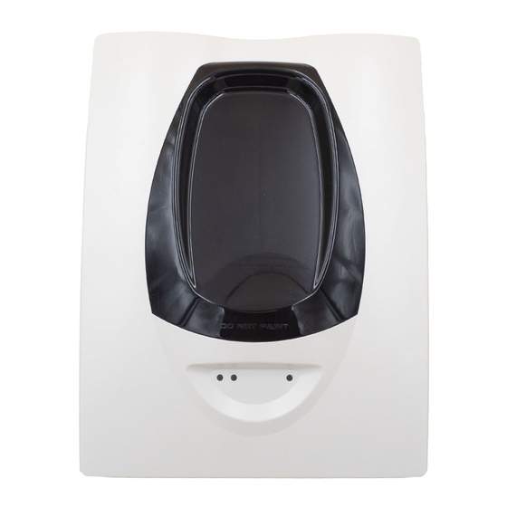
The model 6500R is a conventional long range projected beam smoke
detector designed to provide open area protection. It consists of a
combined transmitter/receiver unit and a reflector. Smoke entering the
area between the two components causes a reduction in the signal
returned to the receiver. When the obscuration reaches alarm
thresholds, selected at the transmitter/receiver unit, the detector
generates an alarm signal. Complete blockage of the beam causes a
fault signal. Slow changes in obscuration due to a build up of dirt or
dust on the lens of the detector are compensated for by a micro-
controller that continuously monitors the signal strength and
periodically updates the alarm and fault thresholds. When the self-
compensation circuit reaches its limit, the detector generates a fault
signal, indicating the need for service. After local testing is complete,
the yellow LED will blink a pattern to indicate the level of drift
compensation employed during the test (see Blinks Output by Yellow
LED table at back of manual).
The model 6500RS includes an integral servo controlled calibrated test
filter, which allows automatic remote alarm testing.
SPECIFICATIONS:
General
Range:
Sensitivity:
Maximum angular misalignment:
Environmental
Temperature Range:
Humidity:
Mechanical
Dimensions (Without Faceplate):
Dimensions (With Faceplate):
Adjustment Angle:
Electrical
Voltage Range:
Avg. Standby Current:
Max. Alarm Current:
Max. Fault Current:
6500RS Test Mode:
Relay Contact Ratings:
Remote Output (Alarm):
PARTS LIST
Description
Transmitter/Receiver Unit
Paintable Trim Ring
Reflector (6500REFL)
Plug in terminal blocks
Instruction Manual
Orange Alignment Assistance Label
Alarm 0 ohm Shunt
Alarm Limiting Resistor 470 ohm
Alarm Limiting Resistor 680 ohm
Alarm Limiting Resistor 1000 ohm
Schottky Diode
DB200-01-01
SMOKE DETECTOR
5 to 70m
70m to 100m using optional
6500-LRK/BEAMLRK
Level 1:
25% Obscuration
Level 2:
30% Obscuration
Level 3:
40% Obscuration
Level 4:
50% Obscuration
Level 5:
30% to 50%
Adjusting (Acclimate)
Level 6:
40% to 50%
Adjusting (Acclimate)
Detector:
± 0.5°
Reflector:
± 10°
-30°C to 55°C
10% to 93% Relative Humidity
(Non-condensing)
230mm x 178mm x 84mm
253mm x 193mm x 84mm
1mm² to 2.5mm²
±10° Horizontal and Vertical
6500R:
10.2 to 32 VDC
6500RS:
15 to 32VDC
17mA at 24 VDC
38.5mA at 24VDC
8.5mA at 24 VDC
500mA peak
0.5A at 30 VDC
Voltage:
15 to 32VDC
dependant on supply
Current:
6mA to 15mA,
Limited by 2.2KΩ Resistor
Quantity
1
1
1
5
1
1
1
1
1
1
1
APPROVED ACCESSORIES
6500-LRK/BEAMLRK
Long Range Kit comprising three additional 20cm x 20cm reflectors,
which may be mounted in a square with the supplied reflector,
permitting the detector to be used for ranges from 70m to 100m.
6500-MMK/BEAMMMK
Multi-Mounting Kit allowing the 6500 to be mounted to ceilings, or to
walls where the detector and reflector cannot be mounted within 10° of
one another. One kit mounts either the transmitter/receiver unit or
reflector. If the transmitter/receiver is mounted on the 6500-MMK/
BEAMMMK, then the 6500-SMK/BEAMSMK must be used. Note that
only a single 20cm x 20cm reflector can be mounted using the MMKs:
The 6500-LRK/BEAMLRK is not compatible with the MMKs.
6500-SMK/BEAMSMK
Surface Mounting Kit for the transmitter receiver (also used in
combination with the MMK) to give an additional 43mm depth to assist
surface mounting and to permit side entry cabling.
6500RTS-KEY
Remote test and annunciator accessory that enables the detector to
be tested remotely, providing test and reset functions, a Red LED to
indicate alarm conditions and a Yellow LED to indicate fault conditions.
DETECTOR MOUNTING
Location
The 6500 must be located in accordance with local standards and
guidelines, for example BS5839 part 1. For general information, refer
to the application guide for projected beam smoke detectors available
on request from your supplier.
Mounting Position
Beam detectors require a very stable mounting surface for proper
operation. A surface that moves, shifts, vibrates, or warps over time
may cause false alarm or fault conditions. Initial selection of a proper
mounting surface will eliminate nuisance alarms and fault signals.
Mount the detector on a stable mounting surface such as brick,
concrete, a sturdy load-bearing wall, support column, structural beam,
or other surface that is not expected to experience vibration or
movement over time. DO NOT MOUNT the beam detector on
corrugated metal walls, sheet metal walls, external building sheathing,
external siding, suspended ceilings, steel web trusses, rafters, non-
structural beam, joists, or other such surfaces. The reflector has a
much greater tolerance to movement than the transmitter/receiver,
hence in cases where only one stable mounting surface as defined
above can be used, the transmitter/receiver unit should be mounted to
the stable surface. See specifications for maximum permissible
angular misalignment; movement outside these limits may cause
nuisance alarms and faults.
Mounting Considerations
•
There must be a permanent clear line of vision between the
detector and the reflector.
•
Reflective objects should be a minimum of 380mm from the line of
sight between the detector and reflector to avoid compromise of
the protected area by reflected light.
•
Direct sunlight or strong lights into the transmitter/receiver unit
should be avoided. There should be a minimum of 10° between the
paths of the light source and the detector beam.
•
Operation of the detector through panes of glass should be
avoided if possible. If it is necessary to pass though glass, the
angle between the beam and glass should be set a minimum of 10°
off perpendicular, and operation through multiple panes should be
avoided.
Mounting
The transmitter/receiver unit may be mounted directly to the wall, with
rear cable entry. The detector base has four primary mounting holes,
one in each corner of the base. All four holes must be used to provide
secure mounting. In order to mount the detector to the wall, the outer
cover must be removed after unscrewing its four retaining screws.
1
I56-2081-013 © System Sensor 2009
Advertisement
Table of Contents

Related Manuals for System Sensor 6500R


Summary of Contents for System Sensor 6500R
- Page 1 6500R AND 6500RS REFLECTIVE TYPE PROJECTED BEAM SMOKE DETECTOR GENERAL APPROVED ACCESSORIES The model 6500R is a conventional long range projected beam smoke 6500-LRK/BEAMLRK detector designed to provide open area protection. It consists of a combined transmitter/receiver unit and a reflector. Smoke entering the...
- Page 2 Refer to the control panel instructions for cable Remote Fault Out T3-3 High impedance +24V Via 2.2k ohms current type limitations limit resistor Table 0: Use of Input – Output Signals . DB200-01-01 I56-2081-013 © System Sensor 2009...
- Page 3 To prevent unwanted alarms, disable the zone prior to applying power. • Ensure power to the detector is “ON”. The alignment of the 6500R is divided into four steps: Coarse alignment, fine adjustment, final gain adjustment, and final verification. ALIGNMENT...
- Page 4 Acclimate Level 2 40 to 50 adjustment step. The digital display readout will turn “OFF” and the yellow LED will remain “ON”. Table 1: Sensitivity Settings DB200-01-01 I56-2081-013 © System Sensor 2009...
- Page 5 Use obscuration filters or reflector test card to initiate Fire and Fault signals Detectors must be tested after installation and following periodic maintenance. The sensitivity of the 6500R may be tested as follows: MAINTENANCE Calibrated Test Filter Method Note:...
- Page 6 Passed a Local Test Number of Percent the detector has blinks output drifted <10% None <20% <30% <40% <50% <60% <70% <80% <90% <100% 0832-CPD-0323 EN54-12 DB200-01-01 I56-2081-013 © System Sensor 2009 Pittway Tecnologica S.r.l., Via Caboto 19/3, 34147 TRIESTE, Italy...
Need help?
Do you have a question about the 6500R and is the answer not in the manual?
Questions and answers