Table of Contents
Advertisement
Quick Links
INSTALLATION AND MAINTENANCE INSTRUCTIONS
6424 Projected Beam Type
Smoke Detector
Specifications
General
Range:
Sensitivity:
Spacing:
Response Time:
Trouble Condition:
Test/Reset Features:
Indicators:
Relays:
Environmental
Temperature:
Humidity:
Mechanical
Weight:
Mounting:
Wiring:
Adjustment Angle:
Electrical (Receiver)
Voltage:
Maximum Ripple Voltage:
Current (24 VDC):
Relay Contacts:
Reset Time:
Start-up Time (after 5 min. reset): 1 Minute Maximum
Power Loss:
Electrical (Transmitter)
Voltage:
Maximum Ripple Voltage:
Avg. Current (24 VDC):
D400-18-00
30 to 330 Feet (9.1 to 100.6 m)
30% ±5% Total Obscuration, or
55% ±5% Total Obscuration
30 to 60 Feet (9.1 to 18.3 m)
Alarm:
15 Seconds Max.
Trouble:
15 Seconds Max.
95% or More Obscuration
Improper Initial Alignment
Self-compensation limit reached (service needed)
Obscuration Filters (ALARM/NO ALARM)
Local Alarm Reset Switch
Remote Test and Reset Switch Capability
(compatible with RTS451 Test Station with Magnet)
Alarm:
Remote Output, Local LED (red)
Trouble:
Remote Output, Local LED (yellow)
Normal Operation:
Local LED (flashing green)
Alignment Aid:
LED Bar Graph (4 red LEDs)
Alarm; Trouble
–22°F to 131°F (–30°C to 55°C)
10% to 93% RH Noncondensing
Receiver:
1.5 lbs (680 g)
Transmitter: 1.3 lbs (590 g)
Ceiling or Wall, Separate Mounting Brackets Provided
Plug with Attached Cable
Ceiling:
±30° Horizontal/60° Vertical
Wall: ±90° Horizontal/60° Vertical
20 to 32 VDC
6.0 volts (Peak-to-peak)
Avg. Standby:
10mA Max.
Avg. Alarm:
28.4mA Max.
Avg. Trouble: 27.1mA Max.
Start-up Surge:
19mA Max.
.5A at 30 VAC/DC
.6 Seconds Max.
Retain Memory for 5 Minute Minimum
18.8 to 32 VDC
5.6 volts (Peak-to-Peak)
10mA Max.
1
firealarmresources.com
3825 Ohio Avenue, St. Charles, Illinois 60174
1-800-SENSOR2, FAX: 630-377-6495
www.systemsensor.com
PRINTED IN MEXICO
I56-494-13R
Advertisement
Table of Contents

Related Manuals for System Sensor 6424


Summary of Contents for System Sensor 6424
- Page 1 INSTALLATION AND MAINTENANCE INSTRUCTIONS 6424 Projected Beam Type 3825 Ohio Avenue, St. Charles, Illinois 60174 1-800-SENSOR2, FAX: 630-377-6495 Smoke Detector www.systemsensor.com Specifications General Range: 30 to 330 Feet (9.1 to 100.6 m) Sensitivity: 30% ±5% Total Obscuration, or 55% ±5% Total Obscuration Spacing: 30 to 60 Feet (9.1 to 18.3 m)
-
Page 2: Before Installing
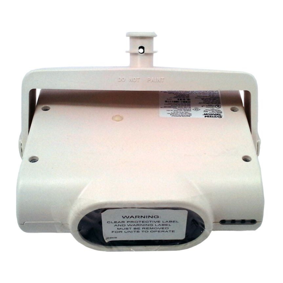
Receiver Wiring Cable Transmitter Wiring Cable General Description Wall Mounting Bracket System Sensor Model 6424 is a long range projected beam Ceiling Mounting Bracket (inside part) smoke detector designed to provide open area protection. Ceiling Mounting Bracket (outside part) It is to be used with UL-listed, separately supplied power Wall Bracket Screw (4-wire) control panels only. -
Page 3: Mounting Locations
Figure 3. Sloped ceiling (shed type): In a room with a smooth ceiling, detectors should be spaced between 30 and 60 feet. One-half that spacing between the 3 F T . beam and the sidewall may be used as a guide. See Figure M A X . -
Page 4: Mounting Brackets
Figure 5. Good and poor mounting surfaces: Poor Mounting Surface Sheet Metal Concrete or Brick Poor Mounting Good Mounting Surface Surface Good Mounting Surface C0540-00 Mounting Brackets Wiring Installation Guidelines Install a ceiling or wall bracket for both the receiver and Always install all wiring in compliance with the National transmitter so that when mounted, the receiver and the Electrical Code, and/or the applicable local codes, and any... - Page 5 Figure 7. Transmitter permanently wired to receiver: CLASS A RETURN LOOP WHITE- WHITE- WHITE- YELLOW YELLOW WHITE-RED STRIPE STRIPE STRIPE STRIPE WHITE-BLACK WHITE-BLACK GRAY GRAY STRIPE STRIPE INITIATING LISTED LOOP EOL POWER WHITE VIOLET WHITE VIOLET SUPERVISION RELAY MODULE WHITE- (SHOWN ENERGIZED) RED-WHITE RED-WHITE...
-
Page 6: Installation
NOTE: The test coil which is shipped with the RTS451 and 2. Mount brackets and connect cables properly as detailed RTS451KEY is not used on the 6424 Beam Smoke above. Detector. 3. Insert the flange of the detector mounting bracket into the keyed hole of the wall or ceiling mounting bracket. - Page 7 Figure 12. Wall mounting: HORIZONTAL ADJUSTMENT SCREW (#10-24 x 1-3/8 in.) METAL WASHER PLASTIC WASHER MOUNTING HOLE WALL MOUNTING MOUNTING HUB MOUNTING HUB BRACKET ALIGNMENT “U” BRACKET LEDs VERTICAL ADJUSTMENT SCREWS (2) CABLE EGRESS HOLE PLUG. USED TO STATUS PLUG UNUSED HOLE. LEDs (RECEIVER ONLY) ALIGNMENT ADJUST...
- Page 8 Figure 14. Rear view receiver: ACCESS DOOR SENSITIVITY SELECT SWITCH 16 CONDUCTOR CABLE ALIGNMENT MODE SWITCH CONNECTOR C0548-00 RESET SWITCH Figure 15. Rear view transmitter: ACCESS DOOR ALIGNMENT MODE SWITCH 6 CONDUCTOR CABLE RANGE CONNECTOR SELECT SWITCH C0549-00 D400-18-00 I56-494-13R PRINTED IN MEXICO firealarmresources.com...
-
Page 9: Alignment Setup
(maximum gain). The alignment adjust pot changes the The alignment of the 6424 is divided into three steps: gain of the amplifier to compensate for differences in alignment setup, alignment of the transmitter, and align- separation between the receiver and transmitter and has ment of the receiver. - Page 10 Detectors must be tested after installation and following LEDs stay lit. periodic maintenance. The sensitivity of the 6424 may be 4) Slide the alignment switch on the transmitter to the tested as follows: NORMAL MODE (N) position (see figure 15) and disconnect any temporary wiring.
- Page 11 B. Remote Test Switch suitable for that purpose. The remote test station, RTS451, can be used with the 6424 beam smoke detector. Follow instructions included with the test station for proper use. See Figure 9 (Remote Test Station) for wiring diagram.
- Page 12 Please include a note describing the malfunction and suspected cause period of three years from date of manufacture. System Sensor makes no of failure. The Company shall not be obligated to repair or replace units other express warranty for this smoke detector.
Need help?
Do you have a question about the 6424 and is the answer not in the manual?
Questions and answers