Advertisement
Table of Contents
www.proform.com
Model No. PFEL94910.0
Serial No.
Write the serial number in the
space above for reference.
QUESTIONS?
If you have questions, or if parts are
damaged or missing, DO NOT
CONTACT THE STORE; please
contact Customer Care.
IMPORTANT: Please register this
product (see the limited warranty
on the back cover of this manual)
before contacting Customer Care.
1-888-533-1333
CALL TOLL-FREE:
Mon.–Fri., 6 a.m.–6 p.m. MT
Sat. 8 a.m.–4 p.m. MT
ON THE WEB:
www.proformservice.com
CAUTION
Read all precautions and instruc-
tions in this manual before using
this equipment. Keep this manual
for future reference.
Serial Number
Decal
USERʼS MANUAL
Advertisement
Table of Contents

Subscribe to Our Youtube Channel
Related Manuals for Pro-Form PFEL94910.0


Summary of Contents for Pro-Form PFEL94910.0
- Page 1 USERʼS MANUAL Model No. PFEL94910.0 Serial No. Write the serial number in the space above for reference. Serial Number Decal QUESTIONS? If you have questions, or if parts are damaged or missing, DO NOT CONTACT THE STORE; please contact Customer Care.
-
Page 2: Table Of Contents
TABLE OF CONTENTS WARNING DECAL PLACEMENT ............. .2 IMPORTANT PRECAUTIONS . -
Page 3: Important Precautions
IMPORTANT PRECAUTIONS WARNING: To reduce the risk of serious injury, read all important precautions and instructions in this manual and all warnings on your elliptical before using your elliptical. ICON assumes no responsibility for personal injury or property damage sustained by or through the use of this product. -
Page 4: Before You Begin
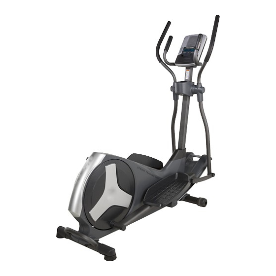
BEFORE YOU BEGIN Thank you for selecting the new PROFORM STRIDE reading this manual, please see the front cover of this ® TRAINER 595 elliptical. The STRIDE TRAINER 595 manual. To help us assist you, note the product model elliptical provides a selection of features designed to number and serial number before contacting us. -
Page 5: Assembly
ASSEMBLY To hire an authorized service technician to assemble the elliptical, call 1-800-445-2480. Assembly requires two persons. Place all parts of the elliptical in a cleared area and remove the packing materials. Do not dispose of the packing materials until assembly is completed. In addition to the included tool(s), assembly requires a Phillips screwdriver and an adjustable wrench... - Page 6 To make assembly easier, read the information on page 5 before you begin. While a second person lifts the rear of the Frame (1), attach the Rear Stabilizer (70) to the Frame with two M10 x 85mm Patch Screws (82). 2.
- Page 7 3. Orient the Upright (2) and the Top Shield Cover (37) as shown. Slide the Top Shield Cover upward onto the Upright. Have a second person hold the Upright (2) near Wire the Frame (1). See the inset drawing. Locate the wire tie in the Upright (2).
- Page 8 5. See the upper drawing. To avoid pinching or damaging the Pulse Wires (28) while you assemble the Handlebar (39), perform the fol- lowing actions: Insert the end of the left Pulse Wire (28) inside the left side of the Handlebar (39). Then, insert the end of the right Pulse Wire (28) inside the right side of the Handlebar (39).
- Page 9 6. The Console (4) can use four D batteries (not included); alkaline batteries are recommended. IMPORTANT: If the Console has been Screws exposed to cold temperatures, allow it to Battery warm to room temperature before inserting Covers batteries. Otherwise, you may damage the console displays or other electronic compo- nents.
- Page 10 8. Attach the Console Cover (32) to the back of the Console (4) with two M4 x 48mm Screws (89). 9. Apply some of the included grease to the axle on the right side of the Upright (2). Identify the Right Upper Body Arm (9), which is marked with a “Right”...
- Page 11 10. Identify the Right Link Arm (98), which is marked with a “Right” sticker, and orient it as shown. Apply some of the included grease to the axle on the Right Link Arm (98). Slide a Link Arm Cover (103) onto the axle on the Right Link Arm (98).
- Page 12 12. With the help of a second person, insert the Right Upper Body Arm (9) into the right Upper Body Leg (6). Attach the Right Upper Body Arm (9) with two M8 x 45mm Button Bolts (76) and two M8 Jam Hexagonal Nuts (77).
- Page 13 14. Attach the Rear Upright Cover (3) to the Upright (2) with three M4 x 16mm Screws (92). Orient the Front Upright Cover (16) so that the indicated arrow is pointing upward. Press the Front Upright Cover (16) into the Rear Upright Cover (3).
- Page 14 16. Press the Rear Shield Cover (59) onto the Left and Right Shields (44, 45). 44 45 17. Make sure that all parts of the elliptical are properly tightened. Note: Some hardware may be left over after assembly is completed. To protect the floor or carpet from damage, place a mat under the elliptical.
-
Page 15: How To Use The Elliptical
HOW TO USE THE ELLIPTICAL HOW TO MOVE THE ELLIPTICAL HOW TO CHANGE THE INCLINE OF THE RAMP Due to the size and weight of the elliptical, moving To vary the motion of the pedals, you can change the it requires two persons. Stand in front of the ellipti- incline of the ramp. - Page 16 HOW TO EXERCISE ON THE ELLIPTICAL Upper Body Arms To mount the elliptical, hold the handlebars or the upper body arms and step onto the pedal that is in the lowest position. Then, step onto the other pedal. Push the pedals until they begin to move with a con- tinuous motion.
- Page 17 CONSOLE DIAGRAM FEATURES OF THE CONSOLE The console also offers six target toning workouts designed to work specific areas of the body. Each tar- The advanced console offers an array of features get toning workout has a recommended ramp incline designed to make your workouts more effective and level and will automatically change the resistance of enjoyable.
- Page 18 HOW TO USE THE MANUAL MODE 4. Follow your progress with the display. 1. Turn on the console. The left display–This display can show the Press any button or begin pedaling to turn on the elapsed time and the console. approximate number of calories you have When you turn on the console, the display will...
- Page 19 5. Measure your heart rate if desired. HOW TO USE A PRESET WORKOUT If there are sheets 1. Turn on the console. of plastic on the Contacts metal contacts on See step 1 on page 18. the handgrip pulse sensor, remove 2.
- Page 20 During the workout, the workout profile will show To restart the workout, simply resume pedaling. your progress (see the drawing on page 19). The The workout will continue until the last segment of flashing segment of the profile represents the cur- the profile flashes and the last segment of the rent segment of the workout.
- Page 21 HOW TO USE A TARGET TONING WORKOUT 3. Adjust the ramp to the recommended incline level. 1. Turn on the console. See HOW TO CHANGE THE INCLINE OF THE See step 1 on page 18. RAMP on page 15 and move the ramp to the rec- ommended incline level for the selected target 2.
- Page 22 HOW TO USE THE SOUND SYSTEM If you stop pedaling for several seconds, a series of tones will sound and the workout will pause. To play music or audio books through the console To restart the workout, simply resume pedaling. sound system while you exercise, plug the audio cable The workout will continue until the last segment of into the jack on the console and into the jack on your...
-
Page 23: Maintenance And Troubleshooting
MAINTENANCE AND TROUBLESHOOTING Inspect and tighten all parts of the elliptical regularly. Replace any worn parts immediately. To clean the elliptical, use a damp cloth and a small amount of mild soap. IMPORTANT: To avoid damage to the console, keep liquids away from the con- sole and keep the console out of direct sunlight. - Page 24 HOW TO ADJUST THE REED SWITCH Locate the Reed Switch (58). Loosen, but do not remove, the M4 x 16mm Screw (92). If the console does not display correct feedback, the reed switch should be adjusted. To adjust the reed switch, you must remove the right disc cover and the right pedal disc.
-
Page 25: Exercise Guidelines
EXERCISE GUIDELINES WARNING: Burning Fat—To burn fat effectively, you must exer- cise at a low intensity level for a sustained period of Before beginning this time. During the first few minutes of exercise, your or any exercise program, consult your physi- body uses carbohydrate calories for energy. - Page 26 SUGGESTED STRETCHES The correct form for several basic stretches is shown at the right. Move slowly as you stretch—never bounce. 1. Toe Touch Stretch Stand with your knees bent slightly and slowly bend forward from your hips. Allow your back and shoulders to relax as you reach down toward your toes as far as possible.
- Page 27 NOTES...
-
Page 28: Part List
PART LIST—Model No. PFEL94910.0 R0610A Key No. Qty. Description Key No. Qty. Description Frame Flywheel Upright Idler Rear Upright Cover C-magnet Console Resistance Motor Water Bottle Holder Motor Bracket Upper Body Leg Upper Arm Resistance Wheel Clamp Left Upper Body Arm... - Page 29 Key No. Qty. Description Key No. Qty. Description Link Arm Bushing Spring Bracket Bushing Cover Latch Screw Link Arm Cover M10 Washer Link Arm Screw Cover Latch Snap Ring Bushing Set M5 x 16mm Screw Ramp Axle Bushing – Userʼs Manual Latch Spring –...
-
Page 30: Exploded Drawing
EXPLODED DRAWING A—Model No. PFEL94910.0 R0610A... - Page 31 EXPLODED DRAWING B—Model No. PFEL94910.0 R0610A...
-
Page 32: Ordering Replacement Parts
ORDERING REPLACEMENT PARTS To order replacement parts, please see the front cover of this manual. To help us assist you, be prepared to provide the following information when contacting us: • the model number and serial number of the product (see the front cover of this manual) •...
Need help?
Do you have a question about the PFEL94910.0 and is the answer not in the manual?
Questions and answers