Table of Contents
Advertisement
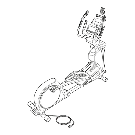
www.proform.com
Model No. PFEL09812.0
Serial No.
Write the serial number in the
space above for reference.
Serial Number
ACTIVATE YOUR
WARRANTY
To register your product and
activate your warranty today,
go to www.proformservice.com/
registration.
CUSTOMER CARE
For service at any time, go to
www.proformservice.com.
Or call 1-888-533-1333
Mon.––Fri. 6 a.m.––6 p.m. MT
Sat. 8 a.m.––4 p.m. MT
Please do not contact the store.
CAUTION
Read all precautions and instruc-
tions in this manual before using
this equipment. Keep this manual
for future reference.
Decal
USER’'S MANUAL
Advertisement
Table of Contents

Related Manuals for Pro-Form 19.0 RE PFEL09812.0


Summary of Contents for Pro-Form 19.0 RE PFEL09812.0
- Page 1 www.proform.com Model No. PFEL09812.0 Serial No. USER’’S MANUAL Write the serial number in the space above for reference. Serial Number Decal ACTIVATE YOUR WARRANTY To register your product and activate your warranty today, go to www.proformservice.com/ registration. CUSTOMER CARE For service at any time, go to www.proformservice.com.
-
Page 2: Table Of Contents
TABLE OF CONTENTS WARNING DECAL PLACEMENT ............. . . 2 IMPORTANT PRECAUTIONS . -
Page 3: Important Precautions
IMPORTANT PRECAUTIONS WARNING: To reduce the risk of burns, fire, electric shock, or injury to persons, read all important precautions and instructions in this manual and all warnings on your elliptical before using your elliptical. ICON assumes no responsibility for personal injury or property damage sus- tained by or through the use of this product. - Page 5 STANDARD SERVICE PLANS...
-
Page 6: Before You Begin
BEFORE YOU BEGIN Thank you for selecting the revolutionary PROFORM ® manual. To help us assist you, note the product model 19.0 RE elliptical. The 19.0 RE elliptical provides an number and serial number before contacting us. The impressive selection of features designed to make your model number and the location of the serial number workouts at home more effective and enjoyable. -
Page 7: Part Identification Chart
PART IDENTIFICATION CHART Use the drawings below to identify the small parts needed for assembly. The number in parentheses below each drawing is the key number of the part, from the PART LIST near the end of this manual. The number following the key number is the quantity needed for assembly. -
Page 8: Assembly
ASSEMBLY •• To hire an authorized service technician to •• In addition to the included tool(s), assembly assemble this product, call 1-800-445-2480. requires the following tools: one Phillips screwdriver •• Assembly requires two persons. one adjustable wrench •• Place all parts in a cleared area and remove the packing materials. - Page 9 2. Have a second person hold the Folding Frame (2) to prevent the elliptical from tipping until this step is completed. Attach the Rear Stabilizer (4) to the Folding Frame (2) with two M10 x 95mm Screws (100). Handle Next, hold the handle on the Rear Stabilizer (4), press the Latch Button (67), and unfold the ellip- tical so that the Rear Stabilizer is resting on the floor.
- Page 10 3. Orient the Front Stabilizer (3) so that the small welded tubes are facing away from the Main Frame (1). Attach the Front Stabilizer (3) to the Main Frame (1) with two M10 x 95mm Screws (100). Welded Tubes 4. Orient the Upright (5) and the Top Cover (27) as shown, and slide the Top Cover upward onto the Wire Tie Upright.
- Page 11 5. Using a plastic bag to keep your fingers clean, apply a generous amount of the included Avoid damaging grease to the Upright Axle (48) and to two Wave the Main Wire Washers (118). Harness (60) Tip: Avoid damaging the Main Wire Harness Grease (60).
- Page 12 7. See drawing 7a. Locate the Pedal Arm Roller (32) on the Right Pedal Arm (12). Set the Pedal Arm Roller on the Ramp (130). See drawing 7b. Apply grease to the axle on the right Crank Arm (39). Orient a Pedal Arm Sleeve (46) so that the flat side is facing the elliptical.
- Page 13 8. Press the Ramp Cover (131) downward onto the Ramp (130). 9. Identify the Right Link Arm (43) and orient it as shown. Apply grease to the axle on the Right Pedal Arm (12). Slide the Right Link Arm (43) onto the axle. Attach the Right Link Arm (43) with an M8 x 16mm Screw (102), a Small Axle Cover (56), and an M8 Washer (95).
- Page 14 10. Identify the Right Upper Body Arm (8). Attach the Right Upper Body Arm (8) to the Right Upper Body Leg (6) with four M8 x 16mm Screws (102). Attach the Left Upper Body Arm (not shown) to the Left Upper Body Leg (7) in the same way.
- Page 15 12. Identify the Front Upright Cover (24) and orient it as shown. Attach the Front Upright Cover (24) to the Upright (5) with four M4 x 16mm Screws (106). 13. Orient the Rear Upright Cover (25) as shown. Connect the wire on the Receiver (144) to the Extension Wire (104).
-
Page 16: The Chest Heart Rate Monitor
THE CHEST HEART RATE MONITOR HOW TO PUT ON THE HEART RATE MONITOR •• Do not expose the heart rate monitor to direct sun- light for extended periods of time; do not expose it to The heart rate temperatures above 122° F (50° C) or below 14° F monitor consists of (-10°... -
Page 17: How To Use The Elliptical
HOW TO USE THE ELLIPTICAL HOW TO PLUG IN THE POWER CORD A temporary adapter may 2-pole Receptacle This product must be grounded. If it should malfunc- be used to tion or break down, grounding provides a path of least connect the Adapter resistance for electric current to reduce the risk of... - Page 18 HOW TO FOLD AND UNFOLD THE ELLIPTICAL To unfold the elliptical, first hold the handle, press the latch button, and lower the frame. Next, pull the pedal When the elliptical is not in use, the frame can be arms away from the handlebars. folded out of the way.
- Page 19 HOW TO EXERCISE ON THE ELLIPTICAL HOW TO LEVEL THE ELLIPTICAL To mount the elliptical, hold the upper body arms and If the elliptical step onto the pedal that is in the lowest position. Next, rocks slightly step onto the other pedal. Push the pedals until they on your floor begin to move with a continuous motion.
- Page 20 CONSOLE DIAGRAM MAKE YOUR FITNESS GOALS A REALITY WITH IFIT.COM Upload your workout results to the iFit cloud and track your accomplishments. With your new iFit-compatible fitness equipment, you can use an array of features on iFit.com to make your Set calorie, time, or distance goals for your fitness goals a reality: workouts.
- Page 21 FEATURES OF THE CONSOLE HOW TO TURN ON THE POWER The advanced console offers an array of features IMPORTANT: If the elliptical has been exposed to designed to make your workouts more effective and cold temperatures, allow it to warm to room tem- enjoyable.
- Page 22 HOW TO SET UP THE CONSOLE HOW TO USE THE MANUAL MODE Before using the elliptical for the first time, set up the 1. Begin pedaling or press any button on the console. console to turn on the console. 1. Create an iFit account. See HOW TO TURN ON THE POWER on page 21.
- Page 23 4. Follow your progress with the display. Time——When the manual mode is selected, this display mode will show the elapsed time. The display can show the following workout information: The matrix offers several display tabs. Press the Display button repeatedly until the desired tab is shown.
- Page 24 When the console is When your pulse is detected, one or two dashes connected to a wire- will appear, and then your heart rate will be shown. less network, the For the most accurate heart rate reading, hold wireless symbol in the the contacts for at least 15 seconds.
- Page 25 HOW TO USE AN ONBOARD WORKOUT As you exercise, you will be prompted to keep your pedaling speed near the target rpm for the cur- 1. Begin pedaling or press any button on the rent segment. When an upward-pointing arrow console to turn on the console.
- Page 26 HOW TO USE A SET-A-GOAL WORKOUT Note: The calorie goal is an estimate of the number of calories that you will burn during 1. Begin pedaling or press any button on the the workout. The actual number of calories that console to turn on the console.
- Page 27 HOW TO USE AN IFIT WORKOUT will burn during the workout and a profile of the resistance settings of the workout. Note: To use an iFit workout, the console must be con- nected to a wireless network (see page 28). An iFit Note: The calorie goal is an estimate of the account is also required (see step 1 on page 22).
- Page 28 HOW TO CHANGE CONSOLE SETTINGS iFit User Setup——To set up a different iFit account, but maintain the existing wireless connection, The console features a settings mode that allows you follow the instructions in the matrix. Note: This to view usage information, to personalize console set- option will be used rarely.
- Page 29 Clear WiFi——To erase the console’’s wireless Press the up, down, left, and right buttons to high- network settings and have it forget the currently light the desired letter or number. Then, press the selected wireless network, follow the instructions in Enter button to select the letter, number, or symbol.
- Page 30 Then, cycle the power of the elliptical: press the computer, smart phone, tablet, or other Wi-Fi power switch on the elliptical to the off position, device. Next, type in the IP address on the con- wait for several seconds, and then press the power sole into the URL bar in your browser.
-
Page 31: Fcc Information
FCC INFORMATION This equipment has been tested and found to comply with the limits for a Class B digital device, pursuant to part 15 of the FCC Rules. These limits are designed to provide reasonable protection against harmful interference in a residential installation. This equipment generates, uses, and can radiate radio frequency energy and, if not installed and used in accordance with the instructions, may cause harmful interference to radio communications. -
Page 32: Maintenance And Troubleshooting
MAINTENANCE AND TROUBLESHOOTING Inspect and tighten all parts of the elliptical regularly. HOW TO ADJUST THE REED SWITCH Replace any worn parts immediately. If the console does not display correct feedback, the To clean the elliptical, use a damp cloth and a small reed switch should be adjusted. - Page 33 Using the flat screwdriver, release the tabs on the HOW TO ADJUST THE DRIVE BELT Access Cover (20), and lift the Access Cover off the elliptical. Then, remove the seven indicated M4 x If you can feel the pedals slip while you are pedaling, 16mm Screws (106), and remove the Left Shield (19).
-
Page 34: Exercise Guidelines
EXERCISE GUIDELINES Burning Fat——To burn fat effectively, you must exer- WARNING: cise at a low intensity level for a sustained period of Before beginning this time. During the first few minutes of exercise, your or any exercise program, consult your physi- body uses carbohydrate calories for energy. -
Page 35: Part List
PART LIST Model No. PFEL09812.0 R1213A Key No. Qty. Description Key No. Qty. Description Main Frame Large Latch Spring Folding Frame Latch Insert Front Stabilizer Long Latch Spring Rear Stabilizer Leg Bearing Assembly Upright M6 Acorn Nut Right Upper Body Leg Small Axle Cover Left Upper Body Leg Upright Bushing... - Page 36 Key No. Qty. Description Key No. Qty. Description Small Snap Ring Long C-pin M8 x 16mm Screw Short C-pin M8 Split Washer #8 x 1/2" Screw Extension Wire Ramp Wire Harness Ramp Cover M4 x 16mm Screw Ramp Bushing M10 x 25mm Screw Ramp Axle M10 x 32mm Washer Lift Motor...
-
Page 37: Exploded Drawing
EXPLODED DRAWING A Model No. PFEL09812.0 R1213A... - Page 38 EXPLODED DRAWING B Model No. PFEL09812.0 R1213A...
- Page 39 EXPLODED DRAWING C Model No. PFEL09812.0 R1213A...
-
Page 40: Ordering Replacement Parts
ORDERING REPLACEMENT PARTS To order replacement parts, please see the front cover of this manual. To help us assist you, be prepared to provide the following information when contacting us: •• the model number and serial number of the product (see the front cover of this manual) ••...
Need help?
Do you have a question about the 19.0 RE PFEL09812.0 and is the answer not in the manual?
Questions and answers